1996 HONDA CIVIC Signal
[x] Cancel search: SignalPage 881 of 2189

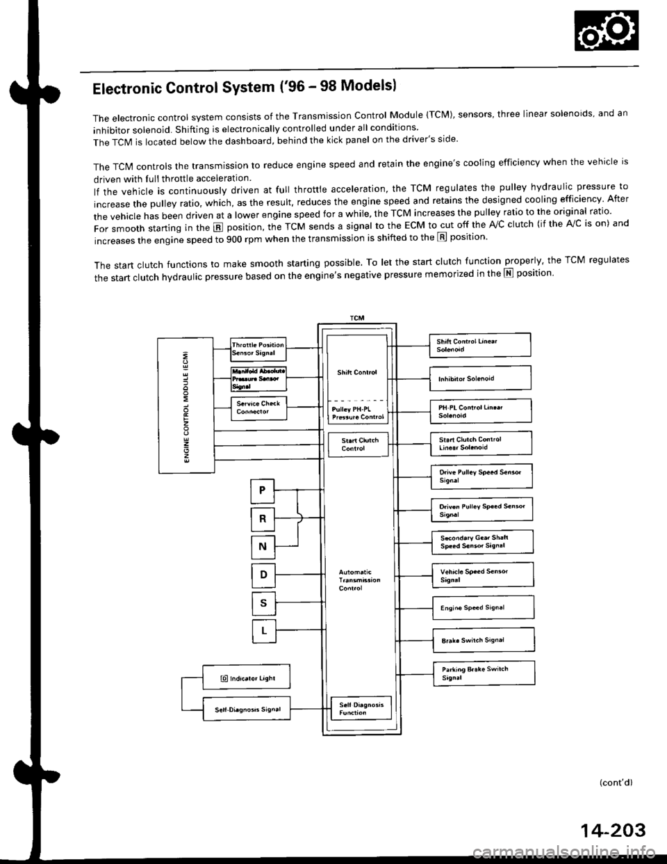
Electronic Control System ('96 - 98 Modelsl
The electronic control system consists of the Transmission control Module (TcM), sensors, three linear solenoids, and an
inhibitor solenoid. Shifting is electronically controlled under all conditions
The TCIM is located below the dashboard, behind the kick panel on the driver's side'
The TcN4 controls the transmission to reduce engine speed and retain the engine's cooling efficiency when the vehicle is
driven with Iull throttle acceleration
lf the vehicle is continuously driven at full throttle acceleration, the TCM regulates the pulley hydraulic pressure to
increase the pulley ratio, which, as the result. reduces the engine speed and retains the designed cooling efficiency After
the vehicle has been driven at a lower engine speed for a while, the TCM increases the pulley ratio to the original ratio.
For smooth starting in the E position, the TcM sends a signal to the EcM to cut off the rvc clutch {if the A!/c is on) and
increases the engine speed to 900 rpm when the transmission is shifted to the E position'
The start clutch functions to make smooth starting possible. To let the start clutch function properly. the TCM regulates
the start clutch hydraulic pressure based on the entine's negative pressure memorized in the E position'
:
:
z
z
z
S*ond.ry G..r Sh:ft
(cont'd)
14-203
Page 884 of 2189

Description
Electronic Control System ('99 - 00 Modelsl (cont'dl
Grade Logic Control System
How it works:
The PcM compares actual driving conditions with memorized driving conditions. based on the input from the vehiclespeed sensor, the throttle position sensor, the manifold absolute pressure sensor, the engine coolant temperature sensor,the brake switch signal, and the shift lever position signal, to control shifting while the vehicle is ascending or descendinga slope.
Ascending Control
When the PCM determines that the vehicle is climbing a hill in E position, the system selects the most suitable shiftschedule (pulley ratio) according to the magnitude of a gradient. so the vehicle can run smooth and have more powerwhen needed. There are three ascending modes with different shift schedules according to the magnitude ot a gradient inthe PCM.
Descending Control
when the PCM determines that the vehicle is going down a hill in E position. the system selects the most suitable shiftschedule (pulley ratio) according to the magnitude of a gradient. This, in combinstion with engine braking, achievessmooth driving when the vehicle is descending, There are three descending modes with different shift schedules accord-ing to the magnitude of a gradient in the PCM.
L
14-206
Page 887 of 2189

Secondary Valve Body
The secondary valve body contains the PH regulator valve. the clutch reducing valve' the start clutch valve accumulator'
and the shift inhibitor valve
PH Regulator Valve
The pi regulator valve maintains hydraulic pressure supplied from the ATF pump. and supplies PH pressure to the
hvdraulic control circuit and the lubrication circuit. PH pressure is regulated at the PH regulator valve by the PH control
pressure (PHC) from the PH control valve.
Cluteh Reducing Valvo
The clutch reducing valve receives PH pressure from the PH regulator valve and regulates the clutch reducing pressure
(cR). The clutch reducing valve supplies clutch pressure (cR) to the manual valve and the start clutch control valve' and
supplies signal pressure to the PH-PL pressure control valve. the shift control valve, and the inhibitor solenoid valve'
Start Clutch Valv€ Accumulator
The start clutch vatve accumutator stabilizes the hydraulic pressure that is supplied to the start clutch'
Shift Inhibitor Valve
The shift inhibitor valve switches the fluid passage to switch the start clutch control from electronic control to hydraulic
control when the electronic control system is faulty. lt also suppliss clutch reducing pressure (cR) to the pitot regulator
valve and the pitot lubrication pipe.
START CLUTCH VALVE
SECONDARY VALVEBODY
SHIFT INHIBITOE VALVE
(cont'd)
PH REGULATOR VAL
REDUCING VALVE
14-209
Page 905 of 2189

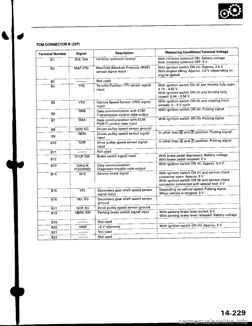
TCM Terminal Voltage/Measuring Gonditions
('96 - 98 Modelsl
TCM Terminal Loc.tions
TCM-A l25P) Connecto.
TCM CONNECTOR A (26P}
TCM-B (22P) Connectot
2418910111213
1115161720232526
Terminal NumbetSignalDsscriptionMoasuring Conditions/Torminsl Vohrgo
A1SC LS_Stan clutch control linear solenoidpower supply negative electrodeEngine idling, E position:Approx. 0.4 VHLC LS-PH-PL control linear solenoid Dowersupply negative electrodeEngine idling, E position:Approx. 0.7 V
Shift control linear solenoid oowersupply negative electrodeEngine idling, E position:Approx. 0.8 V
A4LG1Ground
NEEngine speed signal inputWith engine running: Pulsing signalA6Not used
A7ATP LA/f gear position switch El positionsignal inputInEposition:OVIn other than El position: Approx. 1O VA8ATP Sly'T gear position switch E positionsignal inputIn lg position: 0 VIn other than E position: Approx. 10 VA9ATP DA{/T gear position switch E positionsignal inputIn lll position: 0 VIn other than E position: Approx. 10 VAr0ATP NPA,/T gear position switch E or Eposition signals inputInEorEposition:oVIn otherthan E orE position: Approx. 1O VA11ATP RA,/T gear position switch E positionsignal inputIn lE position: 0 VIn other than E position: Approx. 1O VA.12tGlPower supply systemWith ignition switch ON (ll): Banery voltsgeWith ignition switch OFF: 0 VA13PG1Ground
414Start clutch control linea. solenoidpower supply positive electrodeEngine idling, E position:Approx. 2.5 VA15HLC LS+PH-PL control line8|. solenoid powersupply positive electrodeEngine idling, El position:Approx. 5.0 VA16SH LS+Shift control linear solonoid oowersupply positive electrodeEngine idling, E position:Approx. 6.0 V417Ground
A18Not used
A19Not used
420D INDE indicator light controlWhen l9l indicator light comes on: Approx. jO VWhen lll indicator lighr OFF: 0 VA2'lNot used
422Not used
VBUBack-up power systemAlways battery voltage424Not used
A.25tG1Power supply systemWith ignition switch ON (lt): Baftery voltageWith ignition switch OFF:0 VPG1Ground
L
14-228
Page 906 of 2189

TCM CONNECTOR B (22P}
Terminal NumbelSignalDescriptionMeasuring Conditions/Terminal Voltage
B1SOL INHInhibitor solenoid controlWith inhibitor solenoid ON: Baftery voltage
With inhibitor solenoid OFF: 0 V
82MAP (PB)-M an if old Absol r-rte Pressure IMAP)
sensor signal inPUtWith iqnition switch ON (ll): Approx.2.5 V
With e;gine adling: Approx. 1.0 V (depending on
engine speed)
B3Not used
B4TPS-Throttle Position (TP) sensor signal
input
With ignition switch ON (ll) and throftle fully open:
4.14 - 4.42 VWith ignition switch ON (ll) and throttle fully
closed: 0.44 - 0.56 V
VSSVehicle Speed Sensor (VSS) signal
Inpur
With ignition switch ON (ll) and rotating front
wheelsr 0-5Vcycle
TMBData communication with ECM:
Transmission control data outpUt
With ignilion swltch UN lll): rulslng slgnar
81TMAData communication with EClvl:
PGM Fl control data inPut
With ignition swltch uN {ll,: l-ulslng slgnal
B8NDN SGDriven pulley speed sensor ground
B9NDNDriven pulley speed sensor signal
input
ln other thTnE and E position: Pulsing signal
810NDRDrive pulley speed sensor signal
Input
-tn ottrer ttran E ana E position: Pulsing signal
811Not used
812STOP SWBrake switch signal inPutWith brake pedal depressed: Battery voltage
With brake pedal released: 0 V
813DIAG-H(TXD/RXD)Data communication:Diagnostic trouble code outPut
Wittr ignitio.r s*itct' ON (ll): Approx 5.0 V
814Se-ice ctrect signatWith ignition switch ON (ll) and service check
connector oPen: APProx.5 V
With iqnition switch ON (ll) and service check
"onn"itot. connect"d with special tool: 0 V
Secondary gear shaft speed sensor
signal input
Depending on vehicle speed: Pulsing signal
When vehicle is stoPped: 0 V815VEL
816VEL SGSecondary gear shaft speed sensorgrouno
817NDR SGDrive pulley speed sensor ground
818HBRK SWParking brake switch signal inPutWith parking brake lever pulledr 0 V
With parking brake lever released: Battery voltage
819Not used
B�20VREF+5 V relerenceWith ignition switch ON (ll): Approx 5 V
821Not used
Not used
Page 909 of 2189

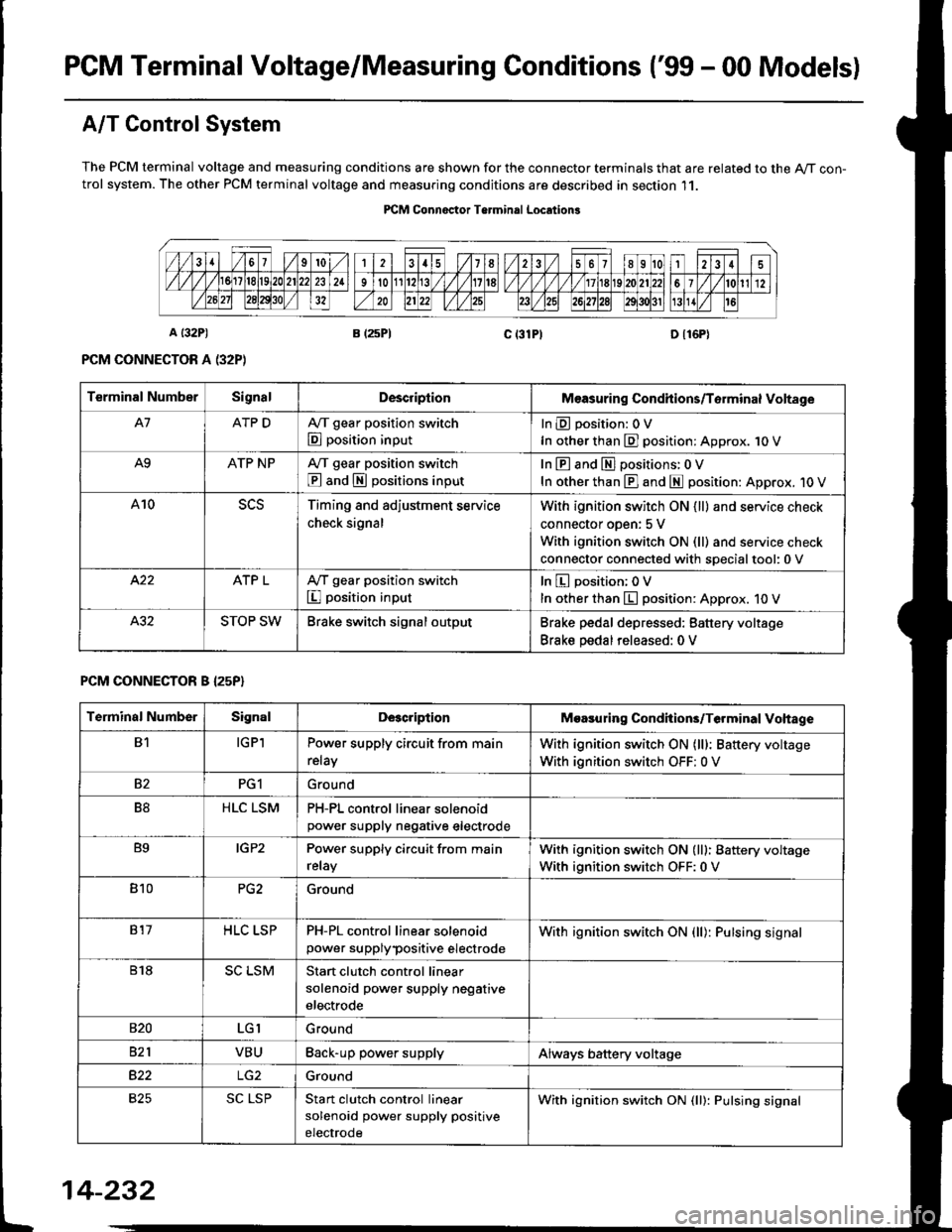
PGM Terminal Voltage/Measuring Conditions ('99 - 00 Modelsl
A/T Control System
The PCM terminal voltage and measuring conditions are shown for the connector terminals that are related to the A/T con-trol system. The other PCM terminal voltage and measuring conditions are described in section 11.
PICM Connoctor Terminrl Location3
Terminal NumberSignalDescriplionMeasuring Condhions/Torminal Voltage
A7ATP DA,/T gear position switch
E position input
InEposition:OV
In other than E] position: Approx. 1O V
A9ATP NPA/T gear position switch
@ and S positions input
In E and El positions: 0 V
In other than E] and E position: Approx. 1O V
A10Timing and adjustment service
check signal
With ignition switch ON {ll} and service check
connector oDen: 5 V
With ignition switch ON (ll) and service check
connector connected with soecialtool:0 v
ATP LA,/T gear position switch
I position input
In E position; OV
In other than E position: Approx. 10 V
STOP SWBrake switch signal outputBrake pedal depressed: Battery voltage
Brake pedal released: 0 V
PCM CONNECTOR B I25P}
Terminal NumberSignalDescriptionMoasuring Condhions/Terminal Vohage
B1IGPlPower supply circuit from main
relay
With ignition switch ON (lll: Battery voltage
With ignition switch OFF: 0 V
82PG1Ground
B8HLC LSMPH-PL control linear solenoidpower supply neqative electrode
B9IGP2Power supply circuit from main
relay
With ignition switch ON (lll: Battery voltage
With ignition switch OFF:0 V
810PG2Ground
817HLC LSPPH-PL control linear solenoid
power supplypositive electrode
With ignition switch ON {ll): Pulsing signal
818SC LSMStart clutch control linear
solenoid power supply negative
electrode
s20LGIGround
821VBUBack-up power supplyAlways battery voltage
B22Ground
825SC LSPStan clutch control linear
solenoid power supply positive
electrode
With ignition switch ON (ll): Pulsing signal
t
14-232
Page 910 of 2189
![HONDA CIVIC 1996 6.G Workshop Manual \a
PCM CONNECTOR D {16P)
14-233
Terminal Numbs]SignalDescriptionMeasuring Conditions/Terminal Voltage
D1VELSecondary gear shaft speed
sensor signal input
Depending on vehicle speed: Pulsing signal
Whe HONDA CIVIC 1996 6.G Workshop Manual \a
PCM CONNECTOR D {16P)
14-233
Terminal Numbs]SignalDescriptionMeasuring Conditions/Terminal Voltage
D1VELSecondary gear shaft speed
sensor signal input
Depending on vehicle speed: Pulsing signal
Whe](/manual-img/13/6068/w960_6068-909.png)
\a
PCM CONNECTOR D {16P)
14-233
Terminal Numbs]SignalDescriptionMeasuring Conditions/Terminal Voltage
D1VELSecondary gear shaft speed
sensor signal input
Depending on vehicle speed: Pulsing signal
When vehicle is stoPPed: APProx. 0 V
02SOL INHlnhibitor solenoid controlWith inhibitor solenoid ON: Battery voltage
With inhibitor solenoid OFF: 0 V
D3SH LSMShift control linear solenoid
power supply negative electrode
D4SH LSPShift control linear solenoid
power supply positive electrode
With ignition switch ON (ll): Pulsing signal
D5VB SOLPower supply for solenoid valvesWith ignition switch ON (ll): Baftery voltage
With ignition switch OFF:0 V
D6ATP RA,/T gear position switch E
position input
InEposition:0V
In other than B position; Approx. 10 V
D]VEL SGSecondary gear shaft sPeed
sensor ground
D8Not used
D9Not used
D10NDNDriven pulley speed sensor signal
anput
In other than E and E position: Pulsing signal
D11NDRDriven pulley speed sensor signal
input
ln other than E and E position: Pulsing signal
D12NDR SGDrive pulley speed sensor ground
D13ATP SA,/T gear position switch E
position input
InE position: 0V
In other than E position: Battery voltage
D14D INDD indicator light controlWhen ignition switch is first turned ON (ll):
Battery voltage for two seconds
In E position: Battery voltage
D15Not used
D16NDN SGDriven pulley speed sensor
grou nd
Page 934 of 2189

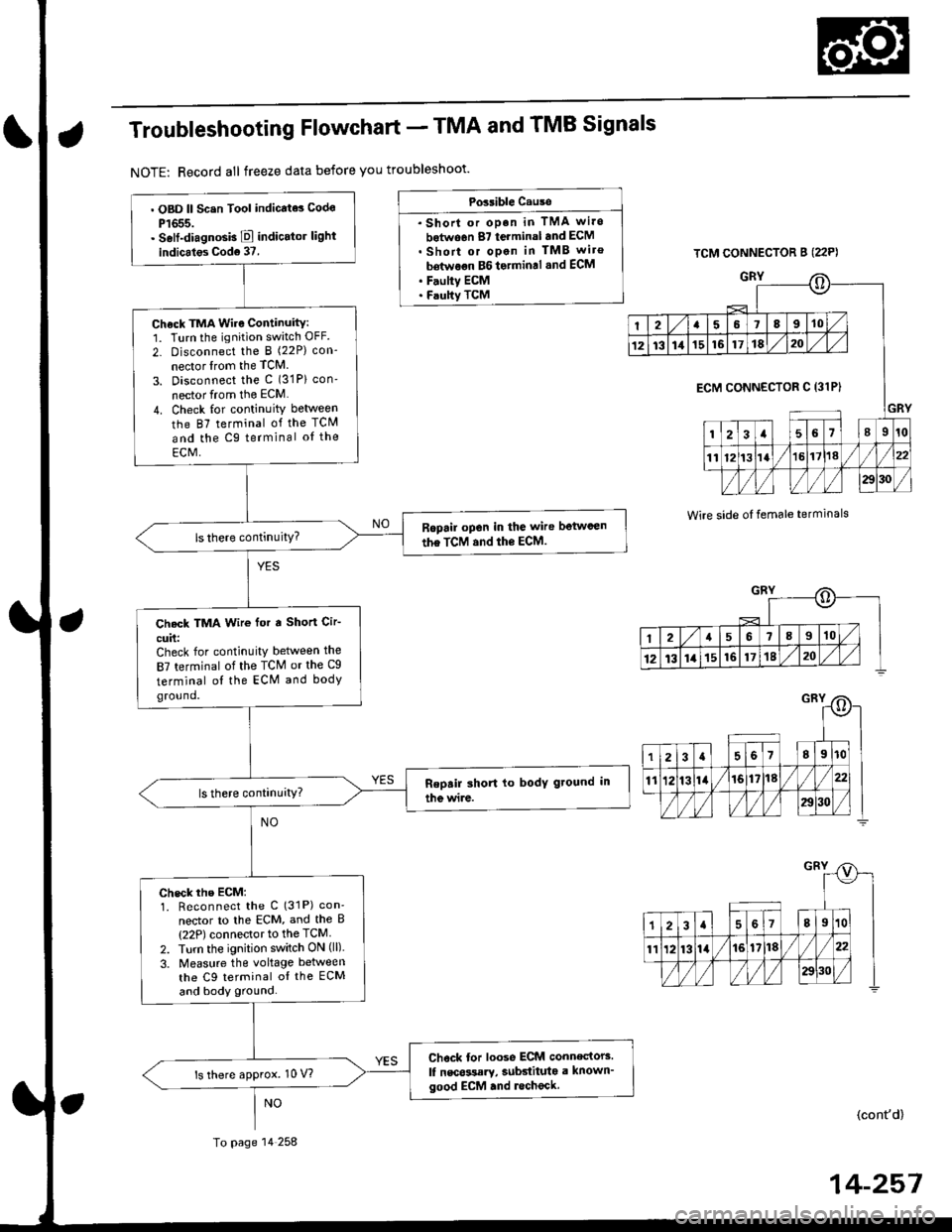
Troubleshooting Flowchart - TMA and TMB Signals
NOTE: Record all freeze data before you troubleshoot'
Possible Cause
. Shorl or op.n in TMA wi.o
botwo6n 87 terminal and ECM. Short or open in TMB wiro
bdtwoon BG to.min.l .nd ECM. F.ulty ECM. Faulty TCM
TCM CONNECTOR B (22P)
GRY
Wire side oI temale terminals
o
I2a58910
1213111516171820
GRY
ECM CONNECTOR C 13lPI
123a56l89r0
1112t3la1618//
29130 /
::)
I2a568910
12t3141516171820
. OBD ll Scsn Tool indicate3 Codo
P1655.. Self-diagnosb E indicator light
indicales Cod6 37.
Check TMA Wire Continuity:1. Turn the ignition switch OFF.
2- Disconnect the I (22P) con-
nector lrom the TCM
3. Disconnect the c (31P) con'
nector from the ECM
4. Check for continuity between
the 87 terminal of the TCM
and the Cg terminal oI the
ECM,
Ropail open in the wire betwcen
the TCM and the ECM.
Check TMA Wir€ for a Short Cir-
cuit:Check for continuity between the
87 terminal of the TCM or the Cg
terminal ol the ECM and bodyground.
check rhe EcM:1. Reconnect the C (31P) con'
nector to lhe ECM, and the B(22P) connector to the TCM
2. Turn the ignition switch ON (ll).
3. Measure the voltage between
the C9 terminal oI the ECM
and body ground.
Chock tor loose ECM connectors.
lf nscossary, subdituta a known'good ECM .nd lecheck.ls there approx. 10 V?
To page 14 258
(cont'd)
14-257