1996 HONDA CIVIC o2 sensor
[x] Cancel search: o2 sensorPage 367 of 2189

Troubleshooting
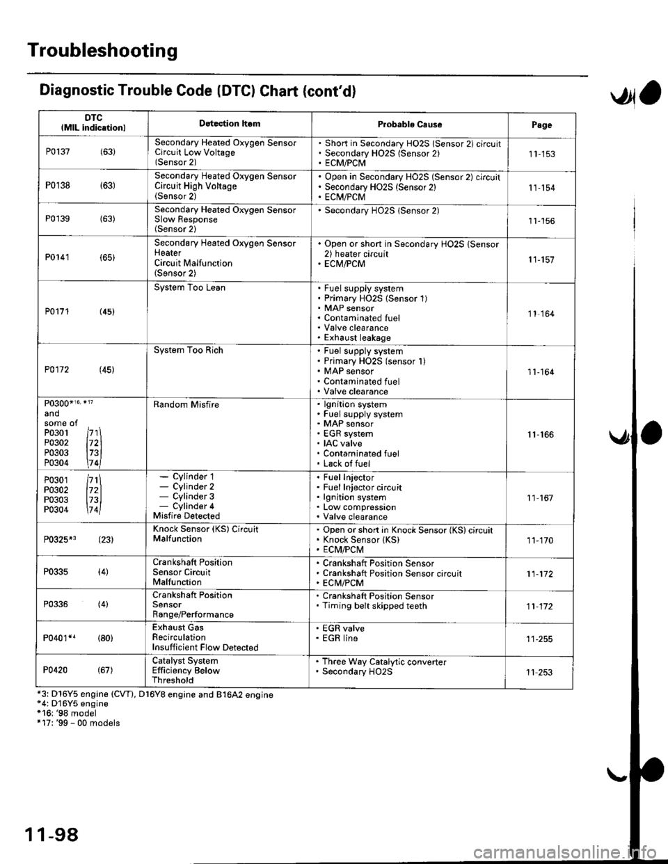
DTClMlL indicationlDatection hsmProbablo CausePage
P0137(63)Secondary Heated Oxygen SensorCircuit Low Voltage(Sensor 2)
Short in Secondary HO2S lSensor 2) circuitSecondary H02S {Sensor 2)ECM/PCI\41 1-153
P0r38 {63)Secondary Heated Oxygen SensorCircuit High Voltage(Sensor 2)
Open in Secondary HO2S (Sensor 2) circuitSecondary HO2S (Sensor 2)EC[I/PCM11-154
P0'139 (63)Secondary Heated Orygen SensorSlow Response(Sensor 2)
Secondary H02S lSensor 2)1l-156
P0141 (65)
Secondary Heated Oxygen SensorHeaterCircuit Malfunction(Sensor 2)
. Open or short in Secondary HO2S (Sensor2) heater circuit. ECM/PCM11-157
P0171 (45)
System Too LeanFuel supply systemPrimary HO2S (Sensor 1)MAP sensorContaminated fuelValve clearanceExhaust leakage
11,164
P0172 (45)
System Too RichFuel supply systemPrimary HO2S (sensor l)MAP sensorContaminated fuelValve clearance
11-164
P0300*16' }l?
andsome ofPo3o1 /r'' \P0302 l72lP0303 l73lP0304 \7 4l
Random Misfirelgnition systemFuel supply systemMAP sensorEGR systemIAC valveContaminated fuelLack of fuel
r1-r66
P0301P0302P0303P0304
/rt\172ll73l\7 4l
- Cylinder 1- Cylinder 2- Cylinder 3- Cylinder 4Misfire Detected
Fuel InjectorFuel Injector circuitlgnition systemLow compressionValve clearance
11 167
P0325*3 (23)Knock Sensor (KS) CircuitMalfunctionOpen or short in Knock Sensor (KS) circuitKnock Sensor {KS)ECM/FCtvl11-170
P0335(4)Crankshaft PositionSensor CircuitMalfunction
Crankshaft Position SensorCrankshaft Position Sensor circuitECM/PCM11-172
P0336(4)Crankshaft PositionSensorRange/Performance
. Crankshaft Position Sensor. Timing belt skipped teeth11-172
P040'�r*r (80)Exhaust GasRecirculationInsufficient Flow Detected
' EGR valve. EGR line
P0420(67)Catalyst SystemEfficiency BelowThreshold
. Th.ee Way Catalytic converter. Secondary HO2S11 253
Diagnostic Trouble Code (DTCI Chat (cont'dl
*3: D16Y5 engine (CVT), D16Y8 engine and B1642 engine*4: D'16Y5 engine*16: '98 model+17: '99 - 00 models
,Jla
1 1-98
Page 368 of 2189

,'o
L
*:The E indicator light and the Maltunction Indicator Lamp (MlL) may come on simultaneously.*1: D16Y5 engine (CVT)"5: '96 D16Y5 engine, D16Y7 engine, D16Y8 engine (sedan).'97 D16Y5 engine, Dl6Y7 engine (coupe: KA, KC models, sedan: KA.
KC, KL (DX) models, hatchback: all models), D16Yg engjne (sedan: KA, KC models)*6: '96 D16Y8 engine (coupe),'97 Dl6Y7 engine (coupe: KL model, sedan: KL (LX) model),'97 D'16Y8 engine (coupe: all models,
sedan: KL model),'98-all models,'99-all models,'00-all models*12: Except A,,/T (D16Y7, D16Y8 enginei*13: A"/T (D16Y7, D16Y8 engine)!l*14:'97 model*16:'98 model" 17: '99 - 00 models
(cont'd)
1 1-99
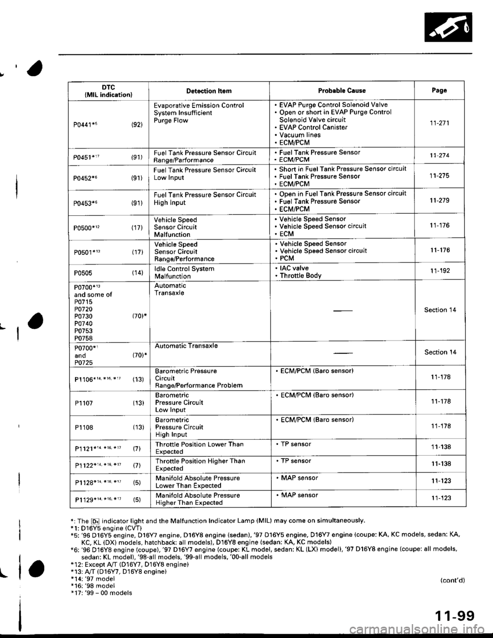
DTC{MlL indication}Detoction lt€mProbable C.usePage
P0441*5 (92)
Evaporative Emission ControlSystem InsufficientPurge Flow
EVAP Purge Control Solenoid VaiveOpen or short in EVAP Purge Control
Solenoid Valve circuitEVAP Control CanisterVacuum linesECM/PCM
11-271
P0451'11 (91)FuelTank Pressure Sonsor CircuitRange/Parformance
. FuelTank Pressure Sensor' ECM/PCM11 274
P0452{6(9r )
Fuel Tank Pressure Sensor CircuitLow Input
Short in FuelTank Pressure Sensor circuatFuel Tank Pres$ure SensorECM/PCM
11-275
P0453*6 {91)
Fuel Tank Pressure Sensor Circuit
High Input
ODen in Fuel Tank Pressure Sensor circuit
Fuel Tank Pressure Sensor
ECM/PCM
11-219
P0500*1, (17)Vehicle SpeedSensor CircuitMalfunction
V€hicle Speed SensorVehicle Speed Sensor circuit
ECM
11-176
P0501*'3 l17l
Vehicle SpeedSensor CircuitRange/Performance
V€hicle Sp€ed SensorVehicle Speed Sensor circuitPCM
r 1- 176
P0505 (14)ldle Control Systemlvl a lfu n ctio n
. IAC valve. Throttle Body11-192
P0700*r3and some ofP0715P0720P0730 (70)*
P0740P0753P0758
AutomaticTransaxle
Section 14
P0700*1and (70)*
P0725
Automatic TransaxleSection 14
(13)Barometric PressureCircuitRange/Performance Problem
. ECM/PCM (Baro sensor)1 1-178
P1107 (13)BarometricPressure CircuitLow Input
. ECM/?CM (Baro s€nsor)11-178
P1108 (13)BarometricPressure CircuitHigh Input
. ECM/PCM lBaro sensor)1 1-178
P1121*'. *16. *'? \71Throttle Position Lower ThanExpected
. I r sensor11-138
P1122'14.*16.*n 17lThrottle Position Higher ThanExpected
. TP sensor11-'138
15)Manifold Absolute PressureLower Than Expected
. MAP sensor1 1'123
P1129*1r.*16.*"(5)Manifold Absolute PressureHigher Than Expected
. MAP sensor't1-123
Page 369 of 2189

Troubleshooting
Diagnostic Trouble Code (DTGI Chart (cont'dl
*7: D16YS engine (M/T)*8: D16Y5, D'16Y8 engine*9: USA model*14r'97 model*15r '96 model
DTC(MlL indicationlDetection lt6mProbablc CausePage
P1162+1 (48)Primary Heated Oxygen Sensor(Sensor 1) CircuitMalfunction
Open or short in Primarv HO2S (Sensor 1Primary H02S (Sensor 1)1 1- 146
P]163' (61)Primary Heated Oxygen Sensor(Sensor '1) CircuitSlow Response
. Primary HO2S (Sensor 1)
11-145
Pl164*r (61)Primary Heated Oxygen Sensor(Sensor l) Cjrcuit Range/Performance Problem
. Primary HO2S (Sensor 1)
1 1- 150
P1165*? (61)Primary Heated Oxygen Sensor(Sensor 1) Circuit Range/Performance Problem
. Primary HO2S (Sensor 1)
11-150
P1166' (41i
Primary Heated Oxygen Sensor(Sensor '1) Heater System ElectricalProblem
Open or short in Primary HO2S (Sensor 1)heater circuitPrimary HO2S (Sensor 1)ECM/PCM
1 1-'161
P1167*' (41)Primary Heated Oxygen SensorlSensor 1) Heater SystemMalfunction
Open in Primary HO2S (Sensor 1) VS+ circuitPrimary HO2S (Sensor 1) HeaterPrimarv HO2S {Sensor 1)1 1- 163
P1168*' (48)Primary Heated Oxygen Sensor(Sensor 1) LABEL Low Input
. Short in Primary HO2S (Sensor 1) LABELcircuit11-151
Pl169*? (48)
Primary Heated Oxygen Sensor(Sensor 1)IABEL High Input. Open in Primary HO2S (Sensor 1)IABELcircuit. Short in ground circuit11.152
P1259*3(221
WEC System MalfunctionWEC Solenoid ValveOpen or short in WEC SolenoidValve circu itVTEC Pressure SwitchOpen or short in VTEC Pressure SwitchcircuitECM,FCM
Section 6
P1297*s (20)Electrical LoadDetector CircuitLow Input
Electrical Load DetectorElectrical Load Detector circuitECM/PCM11-179
Pr298+' l20l
Electrical LoadDetector CircuitHigh Input
Electrical Load DetectorElectrical Load Detector circuitECM/PCM1 1-181
anosome ofP0301P0302P0303P0304
l71ll72ll73ll7 4l
Bandom Misfirelgnition systemFuel supply systemMAP sensorEGR systemIAC valveContaminated fuelLack ol fuel
11-166
1 1-100
Page 370 of 2189

DTC(MlL indicationlDetection ltemProbable CausePage
P1336(54iCrankshaft SpeedFluctuation SensorIntermittent Interruption
. CKF sensor11 183
P1337 (54)Crankshaft SpeedFluctuation SensorNo Signal
CKF sensorCKF sensor circuitECM,PCM
11-'183
P13s9 (8)Crankshaft Position/TopDead Center SensorDisconnected
' CKP/TDC sensor circuit11-187
P1361 (8)Top Dead CenterSensor IntermittentInterruptron
. tuL sensor
11-172
P1362 (8)Top Dead CenterSensor No SignalTDC sensorTDC sensor circuitECIV/PCM
11-172
P1381 {9)Cylinder Position SensorIntermittent Interruption
. CYP sensor11-172
P1382 (9)Cylinder Position SensorNo SignalCYP sensorCYP sensor circuitECM/PCM
11-112
P1456*5(90)
Evaporative Emission ControlSystem Leak Detected {FuelTankArea)
FuelfillcapVacuum connectionFu€ltankFuel tank pressure sensorEVAP bypass solenoid valveEVAP two way valveEVAP control canister vent shut valveEVAP control canisterEVAP purge control solenoid valve
11-283
P1457*6 (90)
Evaporative Emission ControlSystem Leak Detected (EVAP
Control Canister Area)
Vacuum connectionEVAP control canisterFuel tank pressure sensorEVAP bypass solenoid valveEVAP two way valveEVAP control canister vent shut valveFuel TankEVAP purge control solenoid valve
11-283
L
*6: '96 D16Y8 engine (coupe),'97 Dl6Y7 engine (coupe: KL model, sedan: KL (LXl model),'97 D16Y8 engine (coupe: all models,
sedan: KL model),'98-all models,'99-all models,'00-all models.
(cont'd)
1 1-1 01
I ta
Page 371 of 2189

Troubleshooting
Diagnostic Trouble Code (DTCI Ghart (cont'd)
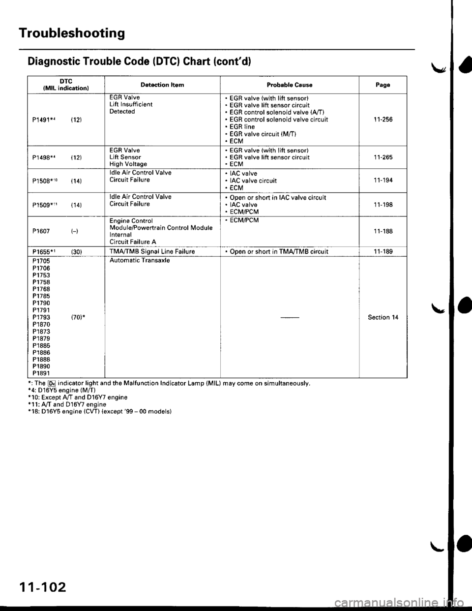
DTClMlL indicationlDetegtion homProbablo CsussPage
P1491*! \12J
EGR ValveLift InsufficientDetected
EGR valve (with lift sensor)EGR valve lift sensor circuitEGR control solenoid valve (A,/I)
EGR control solenoid valve circuitEGR lineEGR valve circuit (M/T)
ECM
't1-256
P1498*. 112)
EGR ValveLift SensorHigh Voltage
EGR valve (with lift sensor)EGR valve lift sensor circuitECM11-265
Pl508*10 (14)
ldle Air Control ValveCircuit FailureIAC valveIAC valve circuitECM
'11-194
{14)
ldle Air Control ValveCircuit FailureOpen or short in IAC valve circuitIAC valveECM/PCM1l-198
P1607 1-)
Engine ControlModule/Powertrain Control lvlodulelnternalCircuit Failure A
. ECM/PCM
11-188
P1655*1 (30)TMA,/TMB Signal Line FailureODen or sho.t in TMA,/TMB circuit11-189
P1705P1706P 1753P1758P1768P1785P1790P1791P1793 (70)*
P1870P1873P1879P1885P1886P1888P1890P1891
Automatic Transaxle
Section 14
*: The E indicator light and the Malfunction Indicator Lamp {MlL) may come on simultaneously.*4: D16Y5 engine (M/T)+10: Except A/T and Dl6Y7 engine*11: A,/T and D16Y7 engine*18: D16Y5 engine (CW) (except '99 - 00 models)
11-102
Page 373 of 2189

PGM-FI System
System Description
CKP/TDC/CYP Sensor
MAP Sensor
IAT SensorTP SensorEGR Valve Lift Sensor*'Primary H02SSecondary HO2SVSSBARO SensorELD*'KS€Starter SignalALT FR SignalAir Conditioning SignalA/T Gear Position SignalBattery Voltage {lGN.1}Erake Switch SignalPSP Switch SignalFuel Tank Pressure Sensor*iVTEC Pressure Switch*5Clutch Switch Signal*6Countershaft Speed SensornBMainshaft Speed Sensorrs
-\
----t /
F;ilrr j"-----fi-tri-'r.;l
Fb"t."'i" d" c;;il
F,h"'c;;tr*".io";-l
@."r.l"sc;;ll
EaM/PcM B""k-p F"""till
r\
-:/
Fuel IniectorsPGM-Fl Main Belay {Fuel Pump)MILIAC Valve!y'C Compressor Clutch RelayRadiator Fan Relay*,Condenser Fan RelayALT*'lcMEVAP Purge Control Solenoid
Primary HO2S HeaterSecondary H02S HeaterEGR Control Solenoid Valve*rEGR valve*6EVAP Bypass Solenoid Valve*'EVAP Control Canister Vent Shut
VTEC Solenoid Valve*5DLCLock-up Control Solenoid Valve*aShift Control Solenoid Valve*3Linear Solenoid Valve*3
*1: Dl6Y5 engine*2: USA model*3: CW (D16Y5 ensine), D16Y8 engine and 81642 ensine*4: '96 D16Y8 engine lcoupe),'97 Dl6Y7 engine (coupe: KL model, sedan: KL (LX) model),'97 D16Y8 engine {coupe: all models, sedan: KLmodel),'98-all models,'99'all models,'00-all models+5: D16Y5, D16Y8,816A2 engine*6: M/T (D16Y5 enginei*7: CVT 1D'l6Y5 engine)+8: A/T (D16Y7, D16Y8 engine)*9: '96 D16Y5 engine,'96 D16Y7 engine,'96 Dl6Y8 engine (sedan),'97 D16Y5 engine,'97 Dl6Y7 engine (coupe: KA, KC models, sedan:KA, KC, KL (LX) models, hatchback: all models),'97 D16Y8 engine (sedan: KA, KC modelsi
PGM-FI Sy3lem
The PGM-Fl system on this model is a sequential multipon fuel injection system.
Fuel iniector Timing and Duration
The ECM/PCM contains memories for the basic discharge durations at various engine speeds and manifold air flow rates.
The basic discharge duration, after being read out from the memory. is further modified by signals sent from various sen-
sors to obtain the final discharge duration.
ldle Air Control
ldle Air Control Valve llAC Valve)
When the engine is cold. the A,/C compressor is on, the transmission is in gear, the brake pedal is depressed, the P/S load
is high, or the alternator is charging, the ECM/PCM controls current to the IAC Valve to maintain the correct idle speed.
lgnition Timing Control
. The ECM/PCM contains memories for basic ignition timing at various engine speeds and manifold air flow rates.
lgnition timing is also adjusted for engine coolant temperature.
. Aknockcontrol system was adopted which sets the ideal ignition timing for the octane rating ofthegasoline used.*3
Othgr Control Funqtions
1. Starting Control
When the engine is started, the ECM/PCM provides a rich mixture by increasing fuel injector duration.
2. Fuel Pump Control
. When the ignition switch is initially turned on, the ECM/PCM supplies ground to the PGM-Fl main relay that sup-plies current to the fuel pump for two seconds to pressurize the fuel system.. When the engine is running, the ECI\4PCM supplies ground to the PGM-FI majn relay that supplies current to the fuel
oumo.
. When the engine is not running and the ignition is on, the ECM/PCM cuts ground to the PGM-FI main relay which
cuts current to the fuel pump.
11-104
INPUTS
ENGINE CONTROL MODULE (ECMY
POWERTRAIN CONTROL MODULE (PCM) OUTPUTS
Page 374 of 2189

3.
5.
6.
1.
Fuel Cut-off Control
. During deceleration with the throttle valve closed, current to the fuel injectors is cut off to improve fuel economy at
speeds over the following rpm:. D16Y5 engine (M/T):850 rpm. D]6Y5 engine (CVT), D'16Y8 engine (USA M/T): 920 rpm
. Dl6Y8 engine (USA A,/I), D16Y7 engine (USA A,/T);910 rpm
. D16Y8 engine (Canada M/T), D16Y7 engine (canada): 990 rpm
' D16Y8 engine (Canada M/T): 1,000 rpm
. 816A2 engine: 970 rpm
. Fuel cut-off action also takes place when engine speed exceeds 6,900 rpm (D16Y5, D16Y7 engine; D'16Y8 engine:
7,000 rpm. 816A2 engine: 8.100 rpm), regardless of the position of the throttle valve, to protect the engine from
over-rewing. With '99 Dl6Y7 engine (A,/T) and '99 D16Y8 engine (A./T), the PCM cuts the fuel at engine speeds over
5,000 rpm when the vehicle is not moving.
IVC Compressor Clutch Relay
When the ECM/PCM receives a demand for cooling from the air conditioning system, it delays the compressor from
being energized, and enriches the mixture to assure smooth transition to the A,/C mode
Evaporative Emission (EVAP) Purge Control Solenoid Valve*'
When the engine coolant temperature is above 154'F (68'C). the ECM/PCM controls the EVAP purge control solenoid
valve which controls vacuum to the EVAP purge control canister.
Evaporative Emission (EVAP) Purge Control Solenoid Valve*a
When the engine coolant temperature above 154"F (68"C), intake air temperature above 32"F (0'C) and vehicle speed
above 0 mile (0 km/h) or [Ay'C compressor clutch on and intake air temperature above 160"F (41'C)], the ECM/PCM
controls the EVAP purge control solenoid valve which controls vacuum to the EVAP purge control canister.
Exhaust Gas Recirculation (EGR) Control Solenoid Valve*?
When EGR is required for control of oxides of nitrogen (NOx) emissions. the ECM controls the EGR control solenoid
valve which supplies regulated vacuum to the EGR valve
Alternator Control
The system controls the voltage generated at the alternator in accordance with the electrical load and driving mode,
which reduces the engine load to improve the fuel economy.
ECM/PCM Fail-safe/Back-up Functions
1. Fail safe Function
When an abnormality occurs in a signal from a sensor, the ECM/PCM ignores that signal and assumes a pre-pro-
grammed value for that sensor that allows the engine to continue to run.
2. Back-uD Function
When an abnormality occurs in the ECM/PCM itself, the fuel injectors are controlled by a back-up circuit independent
of the system in order to permit minimal driving.
3. Self diagnosis Function lMalfunction Indicator Lamp (MlL)l
When an abnormality occurs in a signal from a sensor, the ECM/PCM supplies ground for the lvllL and stores the DTC
in erasable memory. When the ignition is initially turned on, the ECM/PCM supplies ground for the MIL for two sec-
onds to check the MIL bulb condition.
4. Two Trip Detection Method
To prevent false indications, the Two Trip Detection Method is used for the HO2S, fuel metering-related. idle control
system, ECT sensor, EGR system and EVAP control system self-diagnostic functions. When an abnormality occurs,
the ECM/PCM stores it in its memory. When the same abnormality recurs after the ignition switch is turned OFF and
ON 0l) again, the ECM/PCM informs the driver by lighting the MlL. However, to ease troubleshooting, this function is
cancelled when you jump the service check connector. The MIL will then blink immediately when an abnormality
occurs,
5. Two (or Three) Driving Cycle Detection Method
A "Driving Cycle" consists ot starting the engine. beginning closed loop operation, and stopping the engine. lf misfir-
ing that increases emissions is detected during two consecutive driving cycles, or TWC deterioration is detected dur-
ing three consecutive driving cycles, the ECM/PCM turns the MIL on. However, to ease troubleshooting, this function
is cancelled when you jump the service check connector. The MIL will then blink immediately when an abnormality
occurs.
(cont'd)
1 1-1 05
.1.
Page 375 of 2189

PGM-FI System
System Description (cont'dl
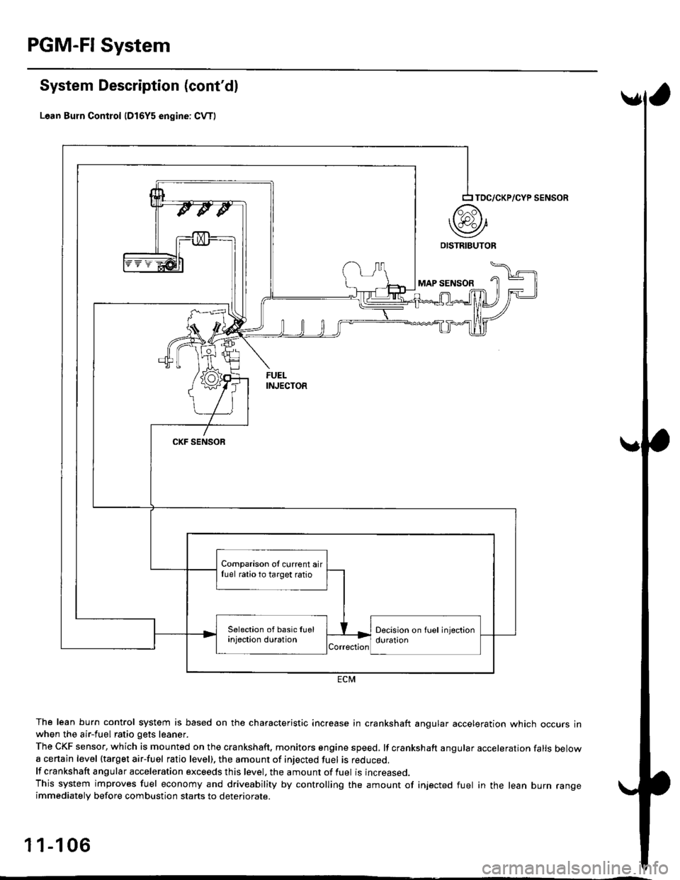
Lean Burn Control {D16Y5 engine: CvT)
The lean burn control system is based on the characteristic increase in crankshaft angular acceleration which occurs inwhen the air-fuel ratio gets leaner.
The CKF sensor, which is mounted on the crankshaft, monitors sngine speed, lf crankshaft angular acceleration falls belowa certain level (target air-fuel ratio level), the amount of injected fuel is reouceo.
lf crankshaft angular acceleration exceeds this level. the amount of fuel is increased.
This system improves fuel economy and driveability by controlling the amount of injected fuel in the lean burn rangeimmediatelv before combustion starts to deteriorate.
1 1-1 06
TOC/CKP/CYP SENSOR
MAP SENSOR
CKF SENSOR
ECM
Comparison oI current airfuel ratio to target ratio