1996 HONDA CIVIC o2 sensor
[x] Cancel search: o2 sensorPage 395 of 2189
PGM-FI System
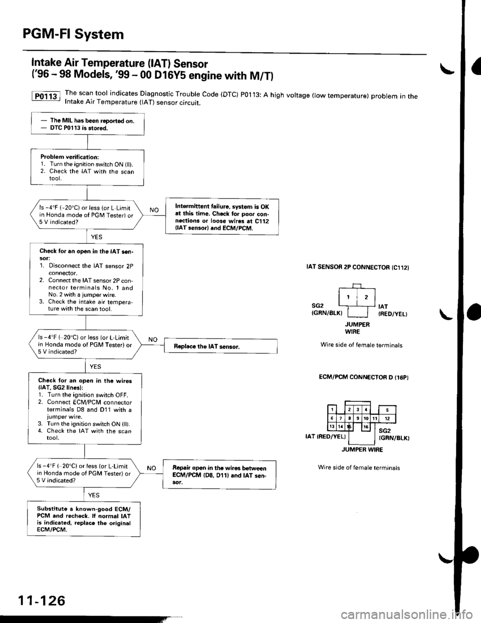
Intake Air Temperature (lAT) Sensor
('96 - 98 Models,'99 - 00 D16Y5 engine with M/Tl
11-126
The scan tool indicates Diagnostic Trouble Code (DTC) POl13: A high voltage flow temperature) problem in theIntake Air Temperature (lAT) sensor circuit,
taT sENsoR 2P CONNECTOn (Cl12l
I' jrl
SG2 '---.]__+ tAT(GRN/BLKI I I IRED/YEL}
JUMPERWIRE
Wire side of female terminals
ECM/PCM CONNECTOR D (16PI
IAT IRED/YEL)sG2(GRN/BLK)
JUMPER WIRE
Wire side of female terminals
The MIL has been reported on.DTC P0113 b sto.6d.
Problem veritication:1. Turn the ignition switch ON (ll).2. Check the IAT with the scantool.
Intermittent tailuJe, systom is OKat this time, Check to. poor con-nections or loose wir.s at C112{lAT senso.l .nd ECM/PCM,
ls -4'F 1-20"C) or less (or L Limitin Honda mode of PGNI Tester) or5 V indicated?
Check for an open in the IAT sen-sol:1. Disconnect the IAT sensor 2pconnector,2. Connect the IAT sensor 2P con-nector terminals No, 1 andNo.2 with a jumper wjre.3. Check the intake air tempera,ture with the scan tool.
ls -4"F ( 20'C) or less (or L-Limitin Honda mode of PGM Tester) or5 V indicated?Repbce the IAT sensor.
Check tor an open in th6 wires{lAT. SGzline!):1. Turn the ignition switch OFF.2. Connect ECM/PCM connectorterminals D8 and D11 with a
3. Turn the ignition switch ON (ll).4. Check the IAT with the scantool.
ls -4"F ( 20'C) or less (or L-Limitio Honda mode ol PGM Tester) or5 V indicated?
R€p6ir opan in the wiro! hweenEC-M/PCM lD8. 011l and IAT sen-
Substitute a known-good ECM/PCM end recheck. lf normal IATis indic.ted, replace the originalECM/PCM.
Page 396 of 2189
L
I
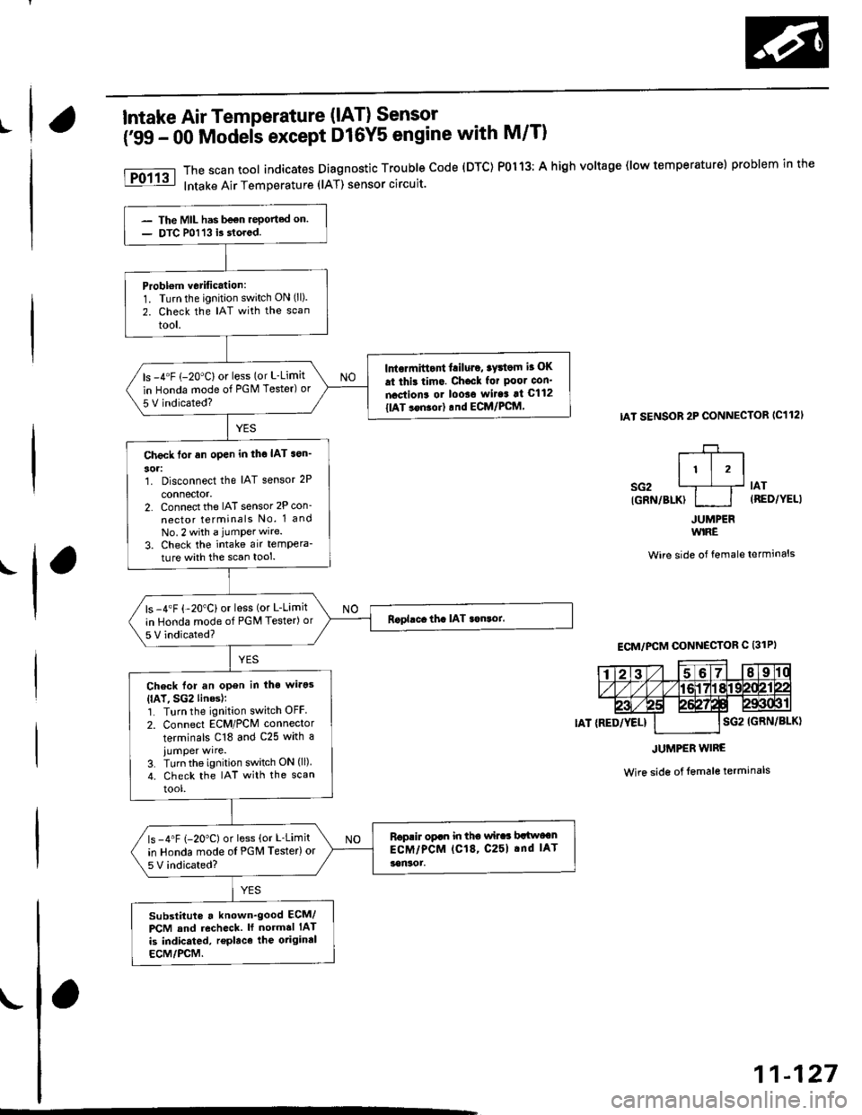
Intake Air Temperature (lAT) Sensor
('99 - 00 Modeis except D16Y5 engine with M/Tl
The scan tool indicates Diagnostic Trouble code (DTC) P0113: A high voltage (low temperature) problem in the
Intake Air Temperature (lAT) sensor circuit.
IAT SENSOR 2P CONNECTOB IC112'
r-+-r
It l,lsG2 L1__f lAr
IGRN/BLK} I I (RED/YELI
JUMPERWIRE
Wire side of female terminals
Wire side of lemale terminals
The MIL has be€n rePorted on.
DTC P0113 i3 stored.
Probl€m vetification:1. Turn the ignition switch ON (ll).
2. Check the IAT with the scan
tool.
Intormittont f.iluro, tyrtom i. OK
.t thi! tim.. Chocl for Poor con'
nactions or looso wit6 !t C112
tlAT ..n!or) rnd ECM/PCftl,
ls -4"F (-20"C) or less (or L-Limit
in Honda mode of PGM Tester) or
5 V indicated?
Check tor an open in tho IAT son'
304:1. Disconnect the IAT sensor 2P
connector,2. Connect the IAT sensor 2P con_
nector terminals No. 1 and
No.2 with a jumPerwire.
3. Check the intake air tempera-
ture with the scan tool.
ls -4"F {-20"C) or less (or L-Limit
in Honda mode of PGM Tester) or
5 V indicated?
Check lor an open in iho wirg3
{lAT, SG2 linesl;1. Turn the ignition switch OFF
2. Connect ECM/PCM connector
terminals C18 and C25 with a
iumper wire.3. Turn the ignition switch ON (ll)
4. check the IAT with the scan
tool.
Roprir opan in tho wilaa brlwocn
ECM/PCM (C18, C25l .nd IAT
!on30r.
ls -4"F (-20"C) or less (or L-Limit
in Honda mode oI PGM Testerlor
5V indicated?
substituts a known'good ECM/
PCM and recheck. ll normal IAT
is indicated, replace the otiginal
ECM/PCM.
ECM/PCM CONNECTOR C (31PI
JUMPER WIRE
11-127
Page 397 of 2189
PGM-FI System
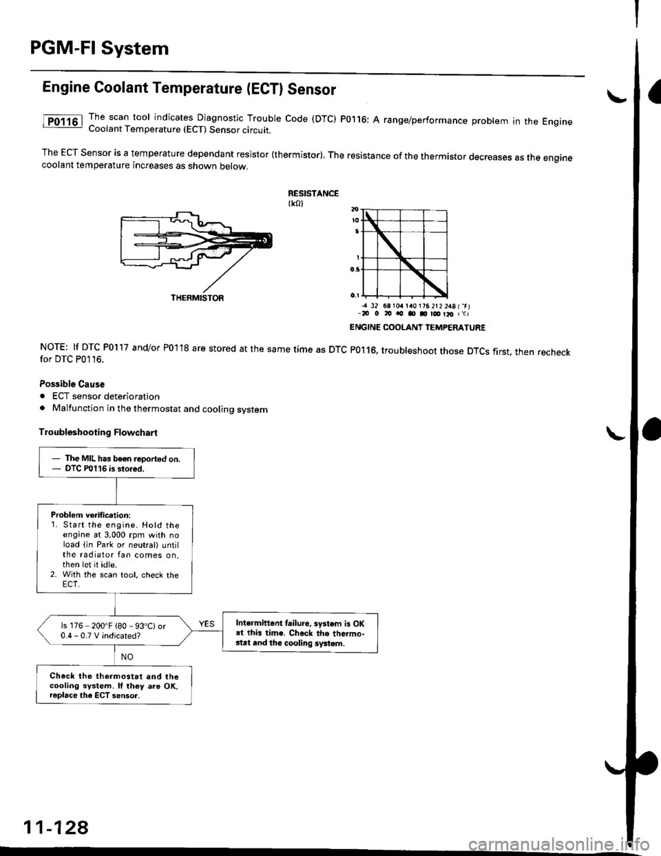
Engine Coolant Temperature (ECTI Sensor
The scan tool indicates Diagnostic Trouble code (DTC) P0116; A range/performance problem in the EngrneCoolant Temperature (ECT) Sensor circuit.
The ECT Sensor is a temperature dependant resistor (thermistor). The resistance of the thermistor decreases as the enginecoolant temperature increases as shown oetow.
RESISTANCE(ko)
NOTE: lf DTC P0117 and/or P01'18 are stored at the same time as DTCfor DTC P0116.
Possible Cause
. ECT sensor deterioration. Malfunction in the thermostat and cooling system
Troubleshooting Flowchart
-a 32 68 r0a la0l?6 2t2 2481'rr-20 o 20 ao o D r@ Il, r'c)
ENGINE COOLANT IEMPERATURE
P0116, troubleshoot those DTCS first. then recheck
11-128
THERMISTOR
- The MIL has bogn reported on.- DTC P0116 is stored.
Problem verification:1. Start the engine. Hotd theengine at 3,000 rpm with noload (in Park or neutral) untilthe radiator fan comes on,then let it idle.2. With the scan tool, check the
Intermiftent lailure. system is OKai thi. time. Ch.ck the thc.mo-stat 6nd thc cooling system.
is 176 200'F {80 - 93'C)or0.0-0.TVindicated?
Check the thermostat and thecooling system. ll they als OK,raplace the ECT sensor.
Page 398 of 2189
|.
'f
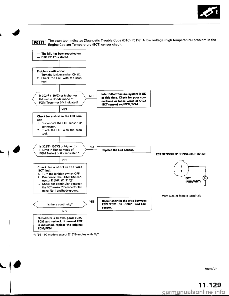
fD;r.tt The scan tool indicates Diagnostic Trouble Code (DTC) P0117: A low voltage (high temperature) problem in the|jg Engine Coolant Temperature (ECTI sensor circuit.
ECT SENSOR 2P CONNECTOR (C122I
Wire side of female terminals
Substitute . lnown-good ECM/PCM .nd rocheck. It normrl ECT
is indic.ted, replaco the original
ECM/PCM,
*:'99 -Oo models except D16Y5 enginewith M/T
(cont'd)
11-129
The MIL has been ,eported on.DTC ml 1 7 is storod.
Problom vorification:1. Turn the ignition switch ON (ll).
2. Check the ECT with the scantool.
Intermittont failulo, sy3tom it OK
at thk tim., Chock for Poor oon-n.ctions or loo!. wiraa at C122IECT 3en orl and ECM/FCM.
ls 302"F (150"C) or higher {orH-Limit in Honda mode ofPGM Tester) or 0 V indicated?
Check toJ a short in the ECT s.n-5('t:1. Disconnect the ECT sensor 2P
connector.2. Check the ECT with the scanrool.
ls 302"F (150"C) or higher {orH-Limit in Hond6 mode ofPGM Testerl or 0 V indicated?
Check for a 3hort in tho wiro
IECT linel:1. Turn the ignition switch OFF.2. Disconnect the ECM/PCM con-nector D (16P) (C {31P))*.3. Check for continuity betweenthe ECT sensor 2P conneclor ter-minalNo, 1 and bodyground.
B.gair short in the wiro bltweenECM/PCM (D2 (C261'l .nd ECT
.1,
Page 399 of 2189
PGM-FI System
Engine Coolant Temperature (ECT) Sensor
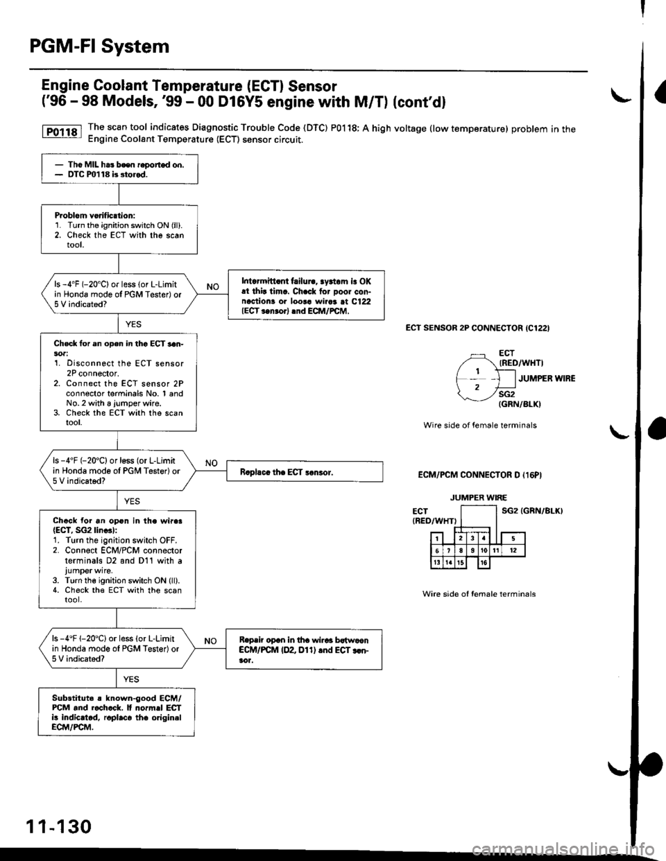
('96 - 98 Models,'99 - 00 D16YS engane with M/T) (cont'd)
The sc€n tool indicates Diagnostic Trouble Code (DTC) P0118; A high voltage (low temperature) problem in theEngine Coolant Temperature (ECT) sensor circuit.
ECt SENSOR 2P CONNECTOR {C1221
ECTIRED/WHTI
JUMPER WIRE
sG2(GRN/BLK)
Wire side of female terminals
ECM/PCM CONNECTOR D Il6PI
sG2 tGRN/81r0
Wire side of Iemale terminals
- Tho MIL ha3 bcen r€oorted on.- OTC m118 b stored.
Problom vorificttion:1. Turn the ignition switch ON (ll).
2. Check the ECT with the scantool.
Intcrmitt.nt failui.. rydom is OKat thir timc. Chack for Door con-naction! or loor! wiaar at C122IECT ..n.orl .nd ECM/rcM,
ls -4"F (-20'C) or less (or L-Limitin Honda mode ol PGM Tester) or5 V indicated?
Chsck lor sn open in thc ECT 3an-soa:1. Disconnect the ECT sensor2P connector.z. Lonnecr rne ELt sensor zFconnector terminals No. 1 andNo.2 with a jumper wire.3. Check the ECT with the scantool.
ls -4'F (-20'C) or loss (or L-Limitin Honda mode ol PGM Testerlor5 V indicated?
Chack for an opon in the wire.{ECT, SG2lin..l:1. Turn the ignition switch OFF.2. Connect ECM/PCM connectorterminals D2 and D11 with ajump€rwire.
3. Turn the ignition switch ON (ll).4. Check the ECT with the scantool.
ls -4'F 1-20'Clor less (o. L-Limitin Honda mode ol PGM Tester)or5 V indicated?
Reprir oprn in tha wirar bstwoonCCM/PCM IDZ Dl1) .nd EGT rcn-aor.
Sub3titut. s known-good ECM/FCM and r.chcck, It normel ECTi! indicatod, roplaco tho origin.lECM/PCM.
JUMPER WIRE
1 1-130
Page 400 of 2189

PGM-FI System
t
I
Engine Coolant Temperature (ECT) Sensor
('99 - 00 Models except Dl6Y5 engine with M/Tl
The scan tool indicates Diagnostic Trouble Code (DTC) P0118: A high voltage (low temperature) problem in the
Engine Coolant Temperature (ECT) sensor circuit.
ECT SENSOR 2P CONNECTOR {C122)
ECT(RED/Wr{T)
JUMPER IVIRE
sG2{GRN/BLK)
wire side of female terminals
ECM/PCM CONNECTOB C 131PI
The MIL has been reported on,
oTC P0118 is stored.
Problem verilication:1. Turn the ignition switch ON (ll).
2. Check the ECT with the scan
tool.
lntormittent failuro, systom is OK
at thb timo. Check lor poor con'nections or 10036 wiraa at C122
{ECT ssnsorl and ECM/rcM.
ls -4'F (-20"C) or less lor L-Limit
in Honda mode o{ PGM Tester) or
5 V indicated?
Check for an open in the Efi sen'
sori1. Disconnect the ECT sensor 2P
connector,2. Connect the ECT sensor 2P
connector terminals No, 1 andNo. 2 with a jumper wire.3. Check the ECT with the scantool.
ls -4"F 1-20"C) or less (or L-Limit
in Honda mode of PGM Tester) or
5 V indicated?
Check for sn open in the wires
IECT. SG2 linesl:1. Turn the ignition switch OFF.2. Connect ECM/PCM connectorterminals C18 and C26 with ajumper wire.3. Turn the ignition switch ON (ll).
4. Check the ECT with lhe scantooi.
Rspair opon in th6 wiros bstwoon
ECM/PCM (Cl8, C26l and ECT
3ensot.
ls -4'F {-20"C) or less (or L-Limit
in Honda mode of PGN4 Tester) or
5 V indicated?
Substitute 6 known-good ECM/PCM and recheck. l{ no.mal EcT
is indicatod, .eplace the originalECM/PCM.
JUMPER WIRE
Wire side of female terminals
11-131
Page 401 of 2189

PGM-FI System
Throttle Position ITP) Sensor ('96 - 98 Models,'99 - 00 D16Y5 engine with M/Tl
The scan tool indicates Diagnostic Trouble Code (DTC) P0122: A low voltage problem in the Throttle Position(TP) sensor circuit.
The TP Sensor is a potentiometer. lt is connected to the throttle valve shaft. As the throttle position changes, the throttleposition sensor varies the voltage signal to the ECM/PCM.
OUTPUT VOLTAGE IVI
1
2
1
0
s{i2(GRN/BLKI
THROTTLEOPENING
FULLTHROTTLE
TP SENSOR 3P CONNECTOR ICllOI
vocz(YEL/BLUI
Wire side ot femal6 terminals
ECM/PCM CONNECTOR D IT6PI
SG2 IGRN/ALKI
{To page l1-133)
Terminal side of male terminals
11-132
- Tho MIL h63 boon roportod on.- DTC m122 i. storcd.
Probl6m voritic€tion:1. Turn the ignition switch ON (ll).
2. Check the throttle positionwith the scan tool.
ls there approx. .49 V whenthe throttle is fully closed andapprox. 4.5 V when the throttleis lully op6ned?
Int..mittent tailura, rFiem ir OKat thit tima. Chock tor Door con-nections or loorc wires !t C110ITP lonrorl .nd ECM/FCM.
Ch6ck lor rn opon in the wire(VCC2linel:
1. Turn the ignition switch OFF.2. Disconnect ths TP sensor 3Pconnector.3. Turn the ignition switch ON lll).4, Measure voltage betweenthe TP sensor 3P conn€ctor ter-minals No. l and No.3.
ls there approx. 5 V?
Check for rn opcn in wire IVCC2line):Measure voltage between ECM/PCM conneclor terminals D10 and011.Chock for rn open or 3hort in TPlon30t:1. Turn the ignition switch OFF.2. At the s€nsor side, measureresistance between the TP sen-sor terminals No. 1 and No. 2with the throttle fully closed.
Roplir op€n in thg wiro batwcsnECM/PCM {DlO) rnd TP ren3or.ls there approx.5 V?
Substitut6 r known-good ECM/PCM and rach6ck. lf pro$ribodvohrge i! now avrilablc, replac€tho o.iginel €CM/FCM.
Wire side of female terminals
Page 402 of 2189
t
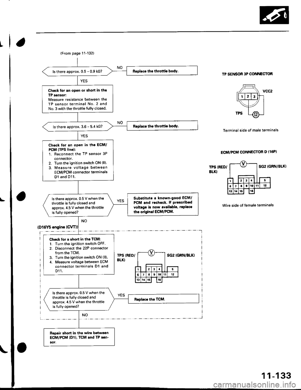
'P SENSOR 3P CONNECTOR
Terminal side of male terminals
ECi'/PCM CONNECTOR D {16PI
TPS IRED/Btx)
IGRN/BLK)
t-
hm
sG2
6Ittotl12
tlt5ta
Wire side ol lemale terminals
lDl6Y5 engine
f
TPS IR€O/BLKISG2 IGRN/BLKI
{From page l1'132}
ls there approx. 0.5 - 0.9 k0?
Check for an opsn or 3hort in thoTP sensor:Measure resislance between theTP sensor terminal No. 2 and
No. 3 with the throttle fully closod.
ls there approx.3.6 - 5.4 k0?
Chock lor an open in the ECM/
PCM ITPS lin6l:1. Reconnect the TP sensor 3P
connector.2. Turn the ignition switch ON {ll}.
3. Measure voltage between
ECM/PCM connector terminals
Dl and D11.
Substitut. r known-good ECM/
PCM and r.ch.ck. lf pt6crib.d
vohrga i. now !Y!il.blo, lcpl.co
tho odginal ECM/PCM.
ls there approx. 0.5 Vwhen the
throttle is fully closed and
approx. 4.5 Vwhen the throttleis fully opened?
Check tor . short in tha TCM:
1. Turn the ignition switch OFF.2. Disconnect the 22P connectorfrom the TCM.3. Turn the ignition switch ON (ll).
/t. Measure voltage between ECMconnector terminals D1 andD11.
ls there approx.0.5 V when the
throftle is tully closed andapprox. 4.5 V whon the throttleis fully opened?
Ropair rhort in the wir€ bdtwconECM/PCM (D11, TCM and TP i.n.
30r,
1 1-133