1996 HONDA CIVIC Fuel tank
[x] Cancel search: Fuel tankPage 1819 of 2189
How To Use This Manual
Circuit Schematics
oa
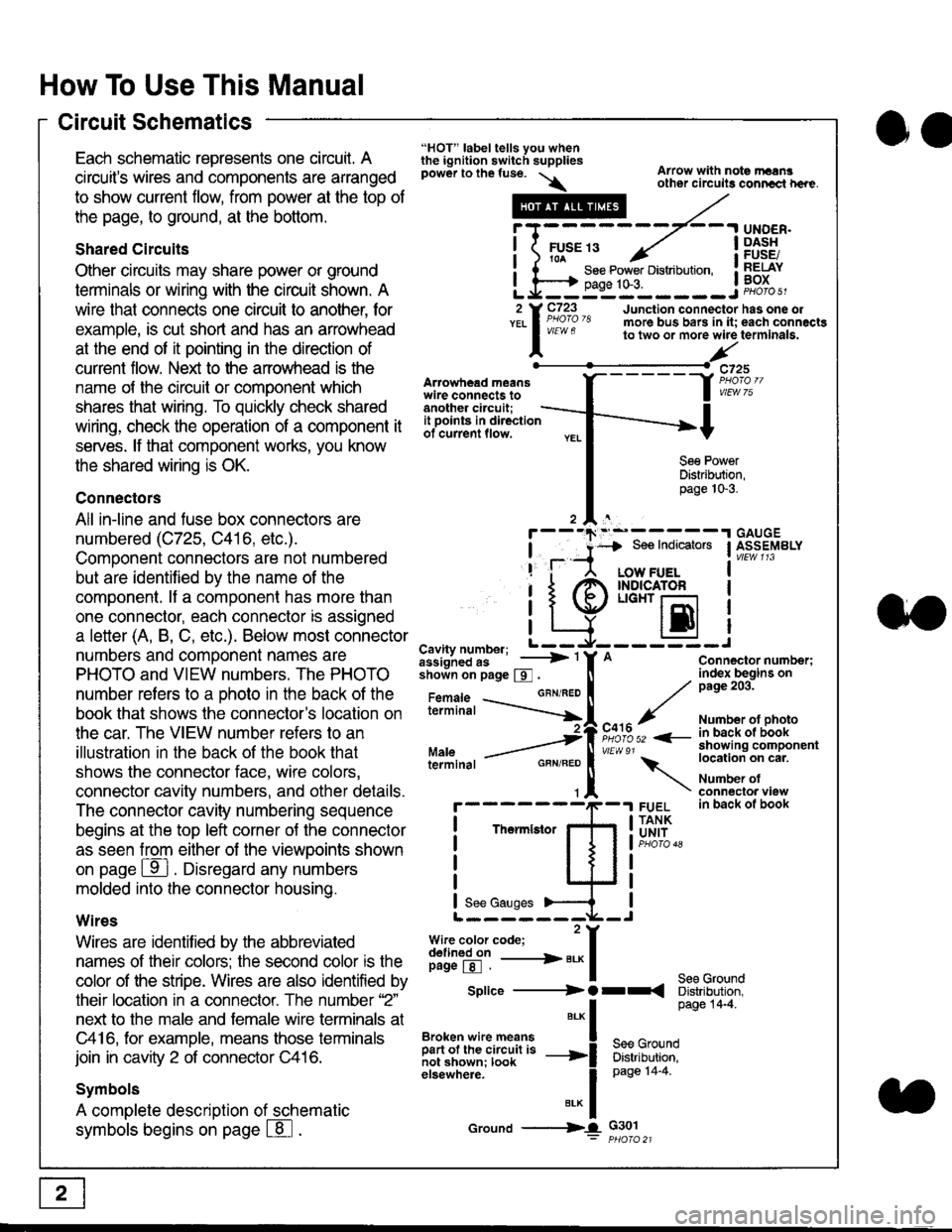
Each schematic represents one circult. A
circuit's wires and components are arranged
to show current flow, from power at the top of
the page, to ground, at the bottom.
Shared Circuits
Other circuits may share power or ground
terminals or wiring with the circuit shown. A
wire that connects one circuit to another, for
example, is cut short and has an arrowhead
at the end of it pointing in the direction of
current flow. Nelit to the anowhead is the
name o{ the circuil or comoonent which
shares that wiring. To quickly check shared
wiring, check the operation of a component it
serves. lf that component works, you know
the shared wiring is OK.
Connectors
All in-line and fuse box connectors are
numbered (C725, C416, etc.).
Component connectors are not numbered
but are identiJied by the name of the
component. lf a componenl has more than
one connector, each connector is assigned
a letter (A, B, C, etc.). Below most connector
numbers and comDonent names are
PHOTO and VIEW numbers. The PHOTO
number refers to a Dhoto in the back of the
book that shows lhe conneclor's location on
the car. The VIEW number refers to an
illustration in the back of the book that
shows the connector face, wire colors,
connector cavity numbers, and other details.
The connector cavity numbering sequence
begins at the top left corner oJ the connector
as seen from either of the viewooints shown
on page ffl . Disregard any numbers
molded into the connector housino.
Wires
Wires are identilied by the abbreviated
names of their colors; the second color rs the
color of the stripe. Wires are also identified by
their location in a connector. The number '2"
next to the male and female wire terminals at
C416, for example, means those terminals
join in cavity 2 of connector C416.
Symbols
A complete description of schematic
symbols begins on page | 8
"HOT" label tells you whenthe ignition switch suppliespower to the fuse. \
Artowhead meanswire connects toanother circuit;
Arrow with note rErngother circuils conncct h€re.
it .a
llu":: ^,{ ii t See Power Distribution, .I t----t oaqe tO-3. IL*--:--------J2 Y C723 Junction connectorYEL I Pao'o'8 more bus bars in it;
I - " " to two or more wire
l,/
-t>?
See PowerDistribution,page 10-3.
UNDER.DASHFUSE/RELAYBOX
has one oleach connactgterminala.
it ooints in directionof current flow.
TheImletor
t_I
Cavity number; L ---
Jiili'iJi!--' -----> '
shoin on page S .
Maleterminal
L?*?l?,-
"'"'I
c725
vlEUt/ 75
Connector number;index begins onpage 203.
Number ot photoin back ol bookshowing componentlocation on cat.
Number ofconneclor viewin back of book
7
GBN/FEO
See Ground
Soe Indicators I ASSEMBLY
:-------J
LOW FUELINDICATOFLIGHT r-l
EI
A
"o'r"/PHOTO 52 <-
\
FUELTANKUNIT
Splice ---------) O rr
".* I Page 14'4'
IBroken wire means | --^ -
iar";J.'It,;,rJ;ii; -----i Bffi,Bili*l
elsewhere. I 0a0e tn-a
IBrK Icround --->lL c301: ptioro 21
Page 1841 of 2189
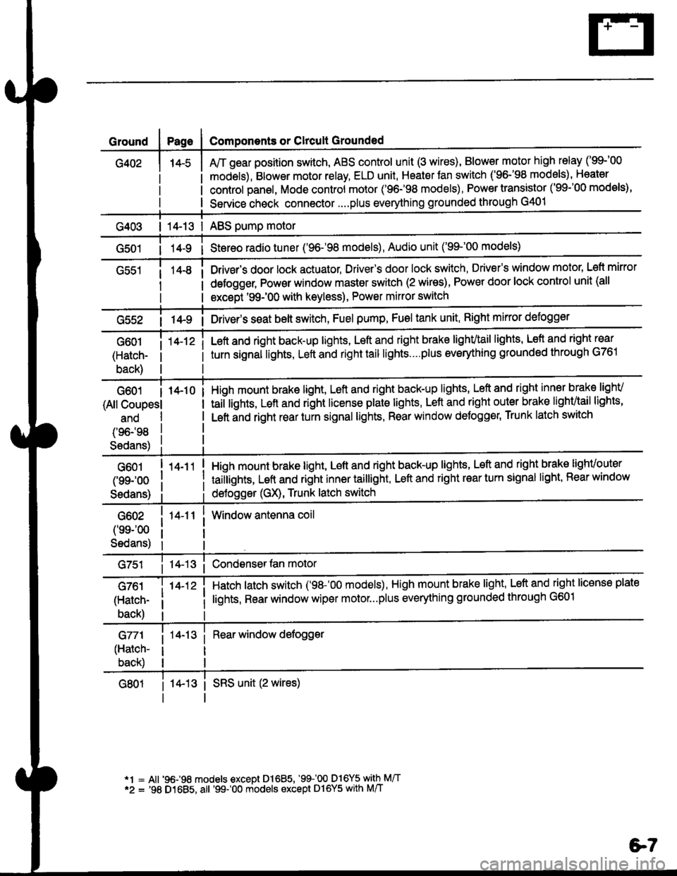
Ground
G402
Components or Clrcult Grounded
Arr gear position switch, ABS control unit (3 wires), Blower motor high relay ('99-'00
models), Blower motor relay, ELD unit, Heater Jan switch ('96-'98 models), Heater
control panel, Mode control motor ('96.�98 models), Power transistor ('99-'00 models),
Service check connector....plus everything grounded through G401
| 14-13 | ABS pump motor
1l-9 i Stereo radio tuner ('96-'98 models), Audio unit ('99-'00 models)
Drivsr's door lock actuator, Driver's door lock switch, Drivefs window motor' Left mirror
defogger, Pow€r window master switch (2 wires), Power door lock control unit (all
except '99-'00 with keyless), Power mirror switch
G55214-9 i Driver's s€at belt switch, Fuel pump, Fuel tank unit, Right mkror defogger
G601
(Hatch-
back)
14-12 iLeft and right back-up lights, Left and right brake lighvtail lights, Lefl and right rear
turn signal lights, Left and right tail lights....plus eveMhing grounded through G761
G601 I 14-10
(All Coupesl
ano
(96198
S6dans)
High mount brake light, Left and right back-up lights, Left and right inner brake lighv
taiilights, Lett and right license plale lights, Lett and right outer brak€ lighvtail lights'
Left and right rear turn signal lights, Rear window deJogger, Trunk latch switch
G601
(99-'oo
Sedans)
G602
('ss-'00
Sedans)
G761
(Hatch-
back)
G771
(Hatch-
back)
14-11
14-12 i
High mount brake light, Left and right back-up lights, Left and right brake lighvouter
taillights, Left and right inner taillight, Left and right rear turn signal light' Rear window
deJogger (GX), Trunk latch switch
Window antenna coil
Hatch latch switch ('98-'00 models), High mount brake light' Left and right license plate
lights, Rear window wiper motor...plus everything grounded through G601
Rear window defogger
14-13 i SRS unit (2 wires)
*1 = All '96-98 models €xcept Dl685, '99100 D16Y5 with M/T*2 = '98 D1685, all '99-'00 models except Dl6Y5 with M/T
e7
Page 1866 of 2189
_t
89c559
Wrth. - - MilrorFUEL , DetoggerTANKUNIT ' RIGHTpaoes 74 ; POWERanj sr -r , MIBRORPHofo 103 | Page 141-2
i-l : i-l
I ltl I
,,:l'it{;
FUELTANKFUEL INTERNALPUMP SOLENOIDPaqe 23-1 VALVEor1q: Page 25-1PHOTO 103 PHOTO 145
r-.| r-'r
tttl
tttlL-J L-J'l
:l'a,t,
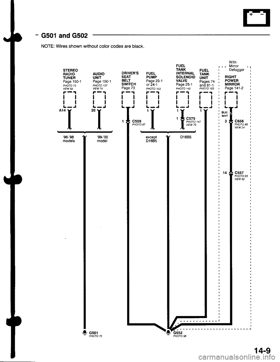
- G501 and G502
'9&'98
m@els
NOTE: Wires shown without color codes are black.
DRIVER'SSEATBELTSWITCHPage 73
tl
tl
STEREORADIO AUDIOTUNER UNITPage 150-1 Page 150-1PHOTO 73 PHOTO 137vtEw 6a vlEw 74
F-.|F-.1
ttll
trtlL-J L-J-.I 'I
93'c557
vtEW 62
'99'00
modelexceprDl685
14
G501
14-9
!-6ssz
Page 1903 of 2189
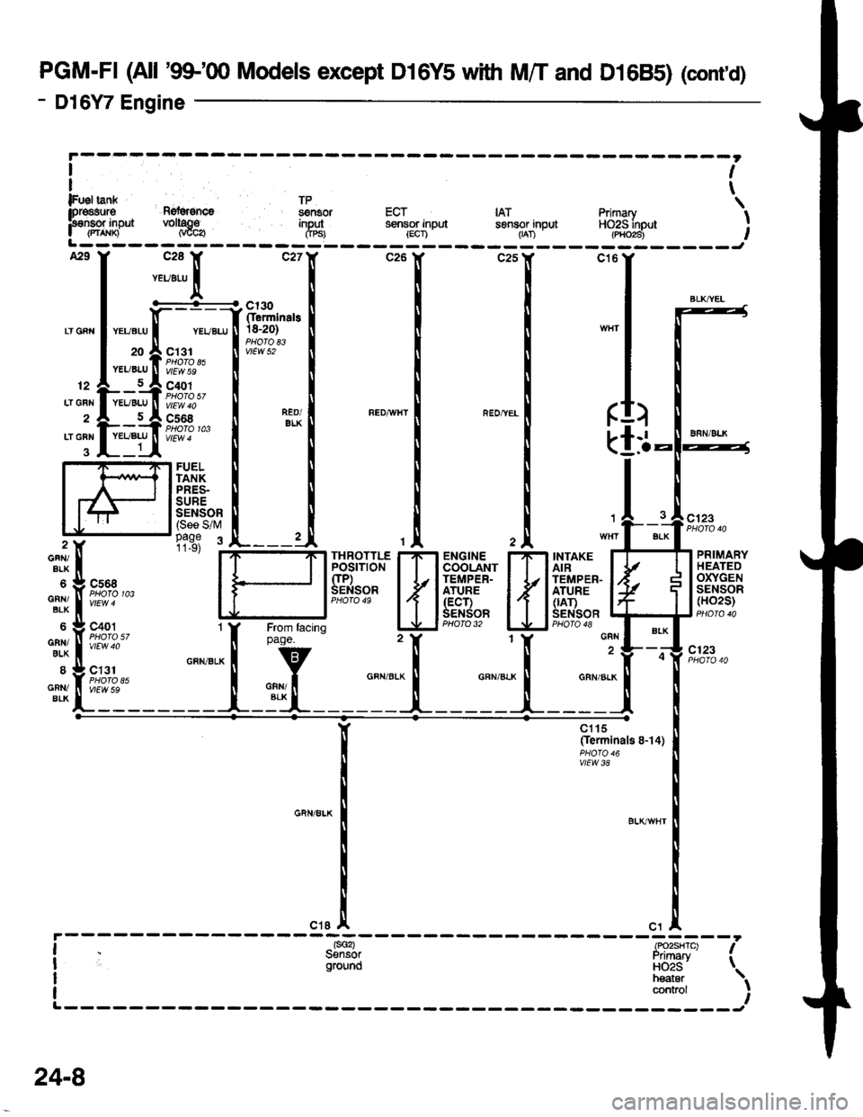
PGM-FI (All '99-'q) Models except D16Y5 with M/T and D1685) (cont'd)
- Dl6Y7 Engine
ct6
(
k
GRN
GRN/ALK
II
)
-l.a
FUELTANKPRES-SURESENSOR(See S/M1
BLK
GFN/BLK
GNN/BLK
6
GAN/8LX
8
GFiI/BIK
tis3 :INTAKEAIRTEMPER-ATURE(|AT)SENSOR
PRIMARYHEATEDOXYGENSENSOR(HO2S)
c'123
c123
cs68PHOTO 103
c401
vtEw 40
ct31
vlEvt S9
FffiflH
{
r,Bi".'#
H
r{
t
f 5:o#'""'"n
rtrt
BLK
at
It
lFueltan* TP \lpr€asura Rg{grsncs ssnsor ECT IAT Primary IF€nsor inpJt voltago input sensor input sensor inpul HO2S inout I| (rt^xn Naca Crpsr lscn - -- 1-ran -- -(p,ioi3i-- ,L------- -----J
BLKT^YEL
clt5(Ierminals 8-14)
vlEw38
contaol
24-8
Page 1913 of 2189
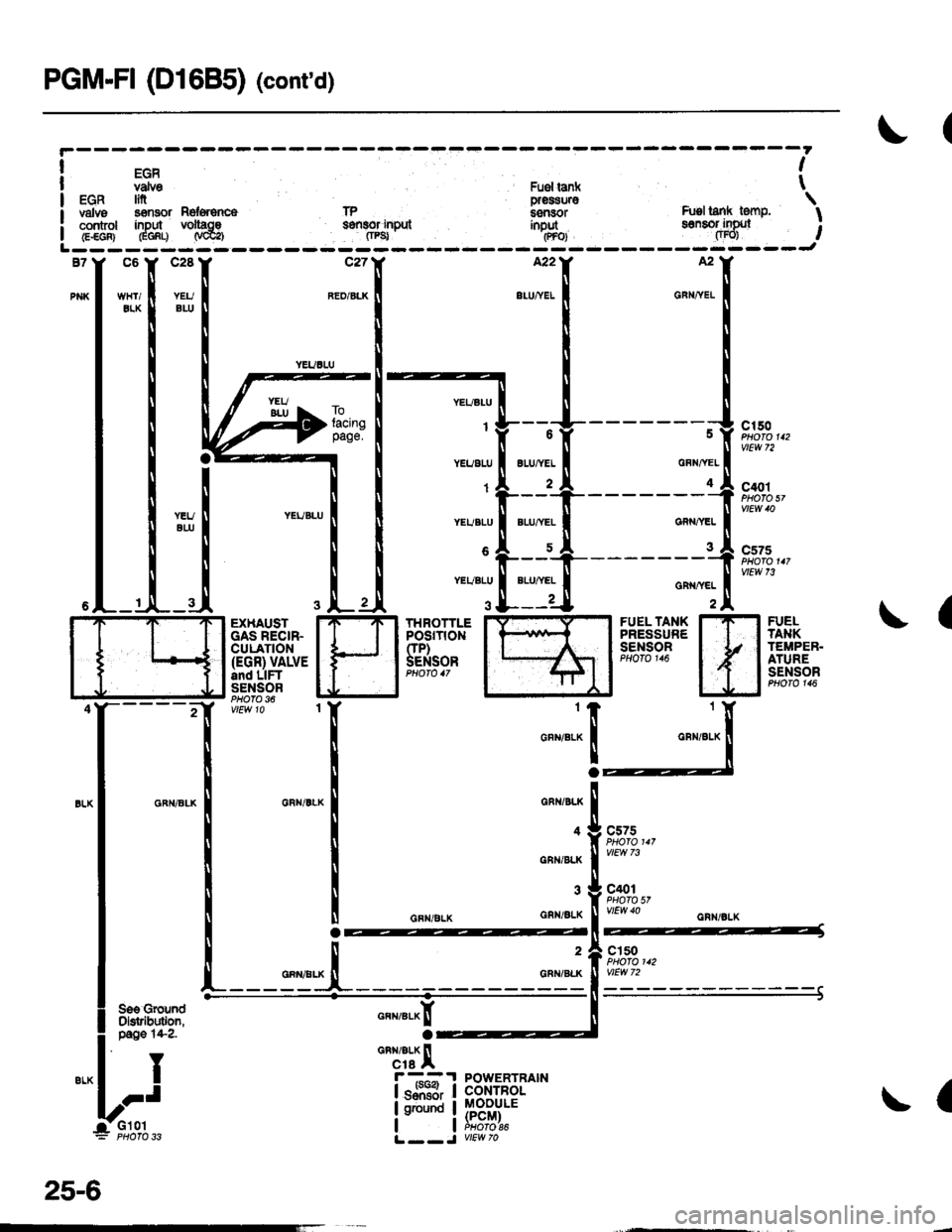
PGM-FI (D1685) (cont'd)
EGRvdvo Fuer ia ( tEGR In pres$uro \valvs s€mor nd*6nc6 lP i.snsor h.tsl lank tenF, Icont ol inDut volt|ce s8fi8of inDul inbut ssnsof ifix, I: control inDln voltac€ s€{tlor input inout sonsol ingJl ;I G.€GF} GGf,q N@a fiPg' .(PFoJ fiFO) ,L------- ------J
j
c2887
c150PHOTO 112
C'ro1PHO|O sl
c575
vtEw 7i
(FUELTA}IKTEMPEB.ATURESENSOR
H1Y
FUEL TANKPRESSURESENSOnPHOTO 116
THROTTLEPOSrT|0NCIP)SENSOR
EXHAUSTGAS RECIR.CULATION(EGR) VALVEand LIFTSENSORPHOfO 36
"""r":x
o
GRI{/BLK
4
GNN/BLK
GNN/gLK
c575
c401PHOfO 57vtEw 40
2
GRN/BL(
cls0
a
POWERTBAINCONTROLMOOULE(PCM)PHOfO 86
I
I
IJ
n"*r"a^[
'rcai/BLX llcre Ar--?
lsJiH,
I ground
I
25-6
Page 1972 of 2189
![HONDA CIVIC 1996 6.G Workshop Manual Low Fuel Indicator Light
l
t
I
I
I
IJ
pag6 106.
,
-ls,T,*-*:lligff*,
l,;l:l?,
A3A
!-{ilril}-1 PowERTRAtNI Lowtuel I CONTROL
I i$grtor I MoD]LE (pcM)
i
S i18l7"*
UNDER.DASHFUSE/RELAYBOXPHOTO 5 HONDA CIVIC 1996 6.G Workshop Manual Low Fuel Indicator Light
l
t
I
I
I
IJ
pag6 106.
,
-ls,T,*-*:lligff*,
l,;l:l?,
A3A
!-{ilril}-1 PowERTRAtNI Lowtuel I CONTROL
I i$grtor I MoD]LE (pcM)
i
S i18l7"*
UNDER.DASHFUSE/RELAYBOXPHOTO 5](/manual-img/13/6068/w960_6068-1971.png)
Low Fuel Indicator Light
l
't
I
I
I
IJ
pag6 106.
,
-ls,T,*-*:lligff*,
l',;l:'l?,'
A3A
!'-{ilril}-1 PowERTRAtNI Lowtuel I CONTROL
I i$grtor I MoD]LE (pcM)
i
S' i18l7"*
UNDER.DASHFUSE/RELAYBOXPHOTO 58
!ra
or*+* i
TFI i
--l------i"I
I
A oxc€pt GX
c503PHO|O 61
AFN/GFI{
9FN/GBN
15
BLU/FEO
c410
vlEw 3s
c'131PHO|O A5vtEw 59
I TANK: UNITThan|tlrlor
So€qauges
L-----J- ----J
Sae GroundDistribution,pa$ 14-9.
74
Page 1973 of 2189
How the Gircuit Works
All Except GX
Do not smoke while working on the fuel system.
Keep open flame away trom the work area. Drain
fuel only into an approved container.
A thermistor is mounted in the fuel tank unit. When
the thermistor is cool, its resistance is very high.
When the thermistor's temperature increases, its
resistance decreases. Fuel in the fuel tank transters
heat away lrom the thermistor fast enough to keep it
cool so the thermistor's resistance stays high and
lhe low fuel indicator light does not come on. When
the fuel level drops below the thermistor, the
thermistor's temoerature increases. Without the fuel
to cool it, the thermistor's resislance decreases,
allowing current to llow through the low fuel
indicator light and the thermistor to ground, and the
low fuel indicator light comes on.
Refer to the Service Manual (Section 23, Electrical)
for specific tests or troubleshooting procedures.
GX
The PCM turns on the low fuel indicator light when
the fuel level is low. The PCM will also blink the
indicator light when a problem is detected by the
fuel tank pressure sensor or the fuel tank
temperature sensor.
Refer to the Service Manual GX Supplement
(Section 11 , Fuel and Emissions) for specific tests
or troubleshooting procedures.
74-1
Page 1980 of 2189
Gauges (cont'd)
- How the Gircuit Works
When the ignition switch is in ON (ll) or START (lll),
battery voltage is supplied through fuse 25 to the
gauges in the gauge assembly.
Speedometer and Odometer
The odometer and soeedometer drive circuits
receive pulses from the vehicle speed sensor
(VSS). The pulse rate increases as the car
accelerates. The frequency and duration of these
input pulses are measured and displayed by the
speedometer, odometer and tripmeter.
Tachometer
The tachometer drive circuit receives pulses from
the ignition control module (lCM) in the distributor
assembly or the ECM/PCM. The solid-state
lachometer then displays these pulses as engine
speed. For each 200 pulses per minute from the
ignition control modul€ (lCM) or the ECM/PCM, the
tachometer displays 100 RPM.
Engine Coolant Temperature Gauge
The engine coolant temperature gauge has two
intersecting coils wound around a permanent
magnet rotor. Voltage applied to the coils, through
fuse 25, generates a magnetic lield. The magnetic
field, controlled by the coolant temperature sending
unit, causes the rotor to rotate and the gauge
needle to move. As the resistance in the sending
unit varies, current through the gauge coils
changes. The gauge needle moves toward the coil
with the strongest magnetic field.
The 6ngine coolant temperature sending unit's
resistance varies from about 137 ohms at low
engine temperature to between 3H6 ohms at high
temperature (radiator fan running).
Refer to the Service Manual (Section 23, Electrical)
for specific tests or troubleshooting procedures.
81-2
(
Fuel Gauge (All except cX)
The fuel gauge has two intersecting coils wound
around a permanent magnet rotor. Voltage applied
to the coils, through tuse 25, generates a magnetic
field. The magnetic field, controlled by the fuel
gauge sending unit, causes the rotor to rotate and
the gauge needle to move. As the resislance in the
sending unit varies, current through the gauge coils
changes. The gauge needle moves toward the coil
with the strongest magnetic field.
The fuel gauge sending unit's resistance varies
from about 2-5 ohms at full, to about 110 ohms at
empty. When you turn the ignition switch off, the
gauge remains at the last reading until you turn the
ignition switch to ON (ll) or START (lll) again,
Refer to the Service Manual (Section 23, Electrical)
for specific tests or troubleshooting procedures.
Fuel Gauge (GX)
The fuel gauge has two intersecting coils wound
around a permanent magnet rotor. Voltage applied
to the coils, through fuse 25, generates a magnetic
field. The magnetic field, controlled by the PCM,
causes the rotor to rotate and the gauge needle to
move. The PCM calculates the gas quantity in the
fuel tank by using the fuel pressure value detected
by the tuel tank pressure sensor and the fuel
temperature value detected by the fuel tank
temperalure sensor, and outputs the signal to the
gauge assembly. The gauge needle moves toward
the coil with the strongest magnetic field.
When you turn the ignition switch off , the gauge
remains at the last reading until you turn the ignition
switch to ON (ll) or START (lll) again. When the
PCM detects a malfunction with the fuel pressure or
temperature, or detects a gas leak, the PCM
reduces the fuel meter to 0.
Refer to the Service Manual GX Supplement
(Section 11 , Fuel and Emissions) for specific tests
or troubleshooting procedures.
a
a