1996 HONDA CIVIC Engine head
[x] Cancel search: Engine headPage 587 of 2189
12.
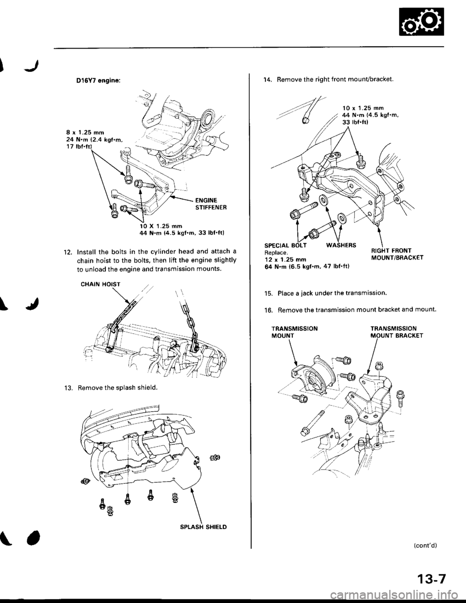
D16Y7 engine:
ENGINESTIFFENER
10 X 1.25 mmIt4 N'm (4.5 kqf'm,33 lbf'ltl
Install the bolts in the cylinder head and attach a
chain hoist to the bolts, then lift the engine slightly
to unload the engine and transmission mounts.
CHAIN HOIST
13. Remove the sDlash shield,
\
8 x 1.25 mm24 N.m {2.4 kgl.m,
SPLASH SHIELD
14. Remove the right front mounvbracket.
'lO x 'l.25 mm44 N'm (4.5 kgl.m,33 rbf.frl
Replace.12 x 1.25 mm
64 N.m t6.5 kgf.m,47 lbf'ft)
Place a jack under the transmission.
Remove the transmission mount bracket and mount.16.
TRANSMISSIONMOUNTTRANSMISSIONBRACKET
(cont'd)
13-7
Page 1086 of 2189
Inspection and Adjustment
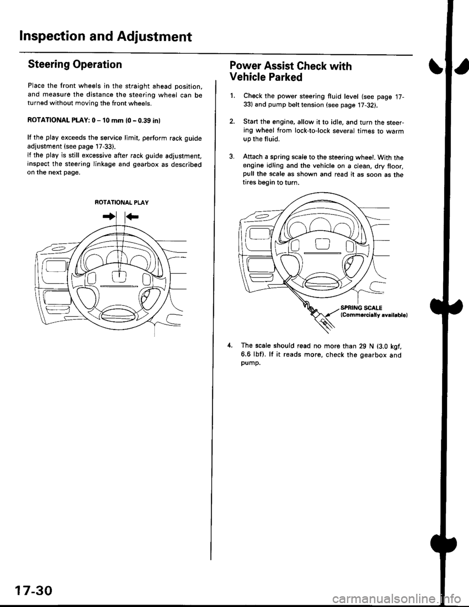
Steering Operation
Place the front wheels in the straight ahead position,
and measure the distance the steering wheel can beturned without moving the front wheels.
ROTATIONAL PLAY: 0 - 10 mm l0 - 0.39 inl
lf the play exceeds the service limit. perform rack guide
adjustment (see page 17-33).
lf the play is still excessive after rack guide adjustment.inspect the steering linkage and gearbox as describedon the nel(t pag€.
ROTATIONAL PLAY
17-30
Power Assist Gheck with
Vehicle Parked
1. Check the power steering fluid level (see page 17-33) and pump belt tension (see page 17-32).
2. Start the engine, allow it to idle. and turn the steer-ing wheel from lock-tolock several times to warm
up the fluid.
3. Attach a spring scale to the steering wheel. With theengine idling and the vehicle on a clean, dry floor,pull the scale as shown and read it as soon as thetires begin to turn.
The scale should read no more than 29 N (3.0 kgf.
6.6 lbf). lf it reads more, check the gearbox andpump,
D0
Page 1089 of 2189
IRack Guide Adjustment
NOTE: Perform rack guide adjustment with the wheels
in the straight ahead Position.
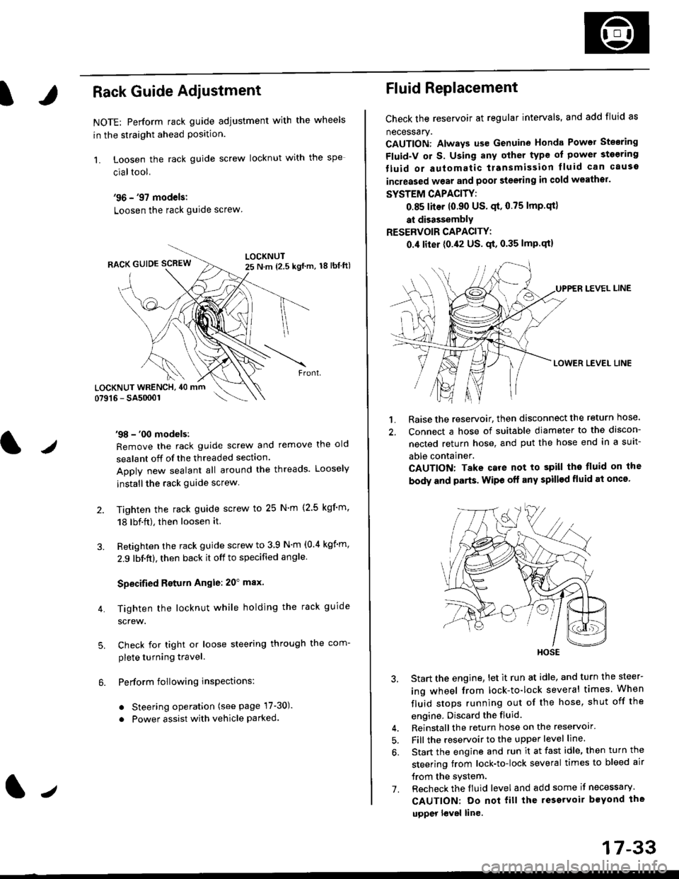
1. Loosen the rack guide screw locknut with the
cialtool.
'96 - '97 models:
Loosen the rack guide screw
'98 - '00 models:
Remove the rack guide screw and remove the old
sealant off of the threaded section.
Apply new sealant all around the threads. Loosely
installthe rack guide screw
Tighten the rack guide screw to 25 N'm (2.5 kgf'm.
18 lbf.ft), then loosen it.
Retighten the rack guide screw to 3 9 N'm (0.4 kgim,
2.9 lbf.ft), then back it off to specified angle.
Specified Return Angle: 20" max.
Tighten the locknut while holding the rack guide
screw.
Check for tight or loose steering through the com-
plete turning travel.
Perform following insPections:
. Steering operation (see page 17-30).
. Power assist with vehicle parked.
4.
LOCKNUT WRENCH, 40 mm
lr
17-33
Fluid Replacement
Check the reservoir at regular intervals, and add fluid as
necessary.
CAUTION: Always us€ Genuine Honda Power Stearing
Fluid-V or S. Using any other type of power sto€ring
tluid or automatic transmission lluid can cause
increased wear and poor steering in cold weathor.
SYSTEM CAPACITY:
0.85 liter 10.90 US' qt,0.75 lmp'qt)
at disassembly
RESERVOIR CAPACITY:
0.4 liter (0.42 US. qt, 0.35 lmP.qt)
LEVEL LINE
LOWER LEVEL LINE
1. Raise the reservoir, then disconnect the return nose.
2. Connect a hose of suitable diameter to the discon-
nected return hose, and put the hose end in a suit-
able container.
CAUTION: Take care not to spill tho fluid on the
body and parts. Wipe off any spill€d fluid at oncs'
3. Start the engine, let it run at idle, and turn the steer-
ing wheel from lock-to-lock several times When
fluid stops running out of the hose, shut off the
engine, Discard the fluid.
4. Reinstall the return hose on the reservoir'
5. Fill the reservoir to the upper level line.
6. Start the engine and run it at fast idle, then turn the
steering trom lock-to-lock several times to bleed air
trom the system.
7. Recheck the fluid level and add some it necessary.
CAUTION: Do not fill the reservoir beYond the
upper l€vel line.
HOSE
Page 1175 of 2189
Master Cylinder/Brake Booster
IRemovaUlnstallation
CAUTION:
. Be care{ul nol to bend or damage the brake lines when
rsmoving the mastsr cYlinder.
. Do not soill brakefluid on the vehicle; it may damage
the paint; if brake fluid does contact the paint, wssh
it off immediatelY with water'
. To prevent spill3, cover the hose ioints with rags or
shop towels.
9. Remove the four booster mountlng nuts
10. Pull the brake booster forward until the clevis is
clear of the bulkhead.
11. Remove the brake booster from the engine com-
panmenr.'12. Install the brake booster and master cylinder in the
reverse order of removal.
CAUTION:
. When connecting the brake lines. make sure
that there is no inte erence between the brake
lines and oth6r Parts.
r Be careful not to bend or damage the brake lines
when installing the master cylinder.
NOTE: lf replacing the master cylinder or brake
booster, check and adiust the pushrod clearance
be{ore installing the master cylinder (see page 19-221'
Fill the master cylinder reservoir, and bleed the
brake svstem (see Page 19-7).
After installation. check the brake pedal height and
brake pedal tree play (see page l9-5) and adjust if
necessary.
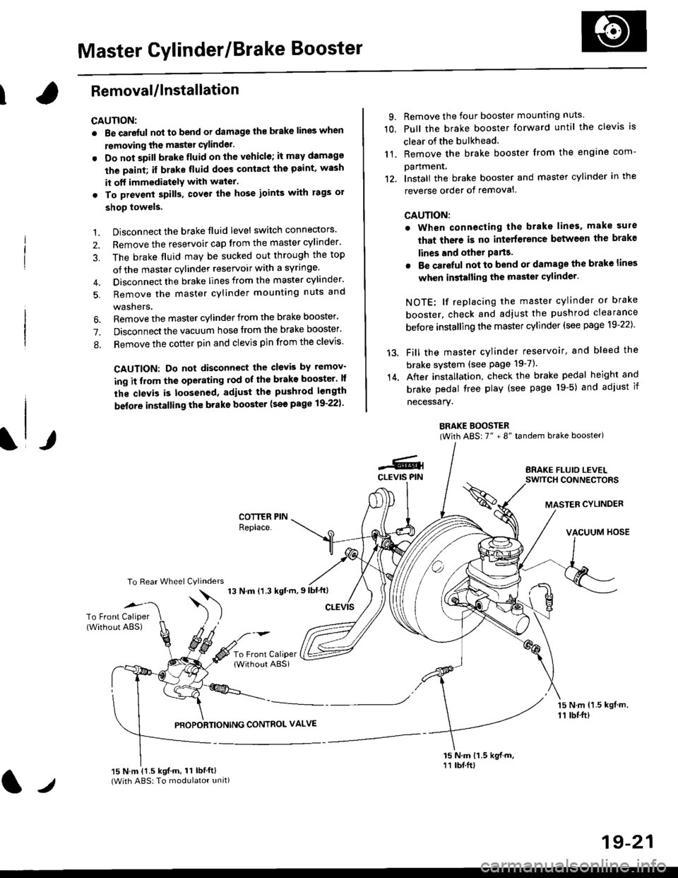
BRAKE BOOSTER(With ABS: 7" + 8" tandem brake booster)
BRAKE FLUIO LEVELSWITCH CONNECTORS
MASTER CYLINDER
VACUUM HOSE
1.
2.
3,
5.
Disconnect the brake fluid level switch connectors'
Remove the reservoir cap from the master cylinder'
The brake fluid may be sucked out through the top
of the master cylinder reservoir with a syrlnge.
Disconnect the brake lines from the master cylinder'
Remove the master cylinder mounting nuts and
washers.
\l/
6. Remove the master cylinder from the brake booster'
7. Disconnect the vacuum hose trom the brake booster'
8. Remove the cotter pin and clevis pin from the clevis'
CAUTION: Do not disconnect the clevb by remov-
ing it from the operating rod of the brako booster' lf
the clevis is loosened, adiust the pushrod length
before installing th€ brake booster (see page 19-221'
COTTER PINReplace.
To Rear Wheel Cylinders
14.
-6.4CLEVIS PIN
To Front Caliper(Without ABS)$
t'N't'ttrnt'-''
To Front CaliperlWithout ABSi
PBOPORTIONING CONTROL VALVE
15 N.m {1.5 kgl m,11 tbtft)
15 N.m {1.5 kgif.m, 11 lbtft}(With ABS: To modulator unit)lr
19-21
Page 1471 of 2189

l'f .
Electrical
Special Toofs .,....................,23-2
Troubleshooting
Tips and Precautions ..............,.................... . 23-3
Five-step Troubleshooting .............. ......... . . 23-5
wire color codes ..........,23-5
Schematic Symbols ........,................... . . .. .... 23-6
Relay and Control Unit Locations
Engine Compartment ...,..................... ... .. . 23'7
Dashboard ......................23-8
Dashboard/Door ......... 23-12*Airbags ................. ....... Section 24
Air Conditioning ......... Section 21
Aftelnator ..........."""" """ 23-112
Anti-lock Brake System {ABS) Section 19*A/T Gear Position Indicator .....................,. .... ... 23-149
Automatic Transmission Svstem .... . ....... Section 14
Batterv ......... . . . ... ...... .......23-91
Blower controls .. . ... Section 2l
Charging System ....'...........23'112
Connector ldentilication and Wire Harness
Routing .................. ......23'13
Cruise Control ............,........23-240
Dash Lights Brightness Controller ............. ....... 23-180
Fan controfs "" 23'126
Fuel PumD ........ . ........ section 11
Fuses/Refay ...............,..,,.. 23'62
PGM-FI Control System ......................,....... Section 1 1
*Gauges
Circuit Diagram ....,.,.......23-131
Fuef Gauge ...........'.'.......23-142
Gauge/lndicator .. . .. 23-129
Ground Distribution .. . 23-75
Heatei controls .. . ..... Section 21*Horn................. ...............23-196
*tgnition Switch ....................23-89
lgnition System .......,.... 23-102
*lntegrated Control Unit ....................................... 23-156
fnterlock System ,........ . . , ,23-144
Lighting System . . . .. ......... 23-161
Lights, Exterior
Back-up Lights ..'............23'171
Brake Lights .................. 23'174
Daytime Bunning Lights (Canadal ............... 23'166
Front Parking Lights ......,................ .'. .......... 23-167
Front Turn Signal Lights .......... . . ............ ..,.23-167
Headtights ....".'....-... ..... 23'167
High Mount Brake Light ...................... ... .23'179
License Plate Lights ...... 23'176
Taitfights ................ .......23'171
lnterior Lights ..-.......,, . 23-142
Moonroof ..,.................,........ 23-235
Power Distribution ....... . . .23-61
Power Door Locks .......,,,. .23'251
Power Mirrors ,..............,.,...23'206
Power Relays ....... . ...... . . .. 23-86
Power Windows ............,,....23-220
Rear Window Defogger .......................... . . ... . . 23-2OO
Spark Plugs . ..... . ........ .....23-111
Slarting System ................23-93*stereo Sound Svstem ,................. ..... ... . ... ,.,.,,23'147'Supplemental Restraint System (SRS) ... . Section 24
Turn Signal/Hazard Flasher System .......'.'....-... 23-173
*Undel-dash Fuse/Relay Box ............,.................. 23-85
vehicfe soeed sensor (VSSI """" ""' 23-140+Wipers/Washers .........,.,.,...23-214
NOTE: Unless otherwise specified, references to auto-
matic transmission (Mf) in this section include the CVT.
Page 1498 of 2189
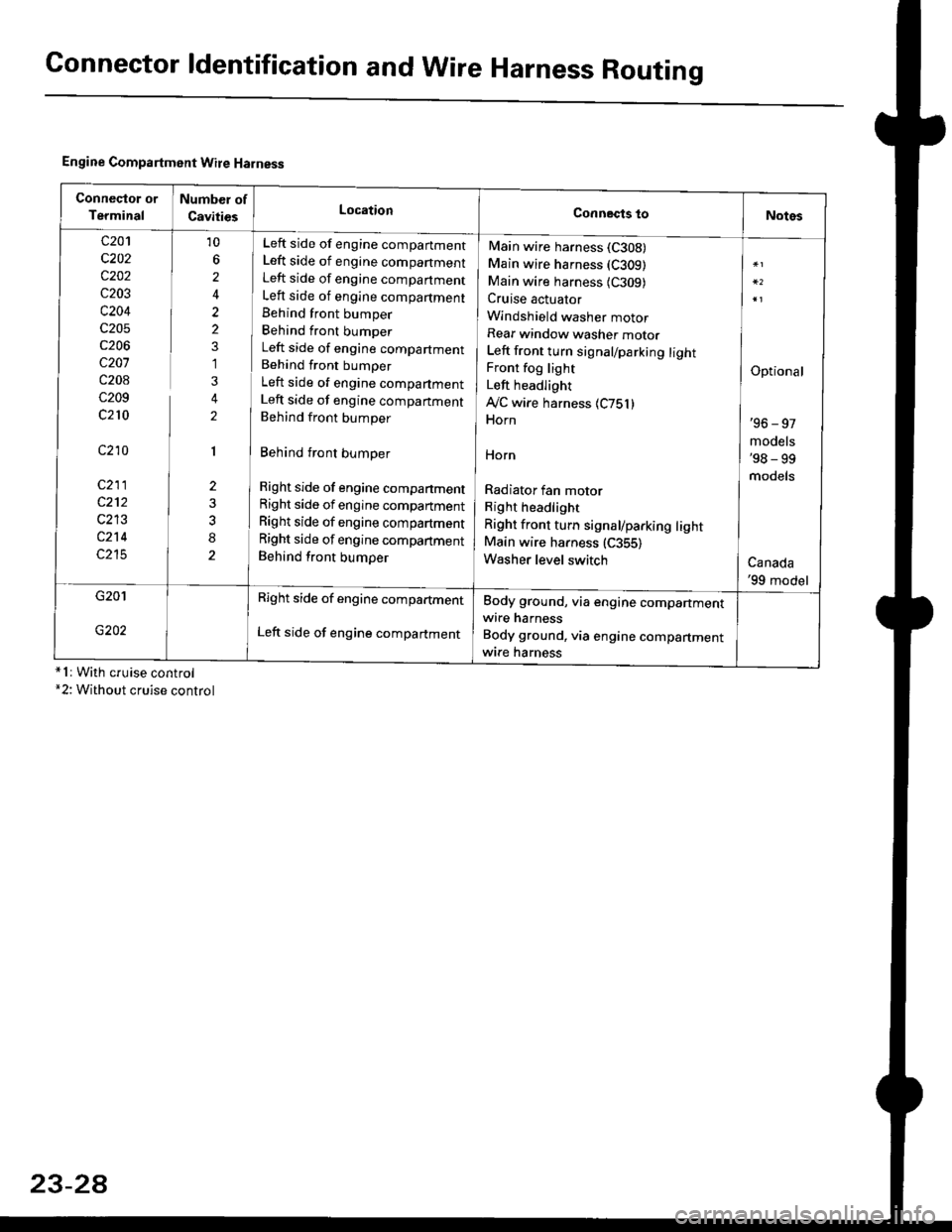
Connector ldentification and WireHarness Routing
Engine Compartment Wire Harness
conneqtor of
Terminal
Number of
CavitiesLocationConnects toNotes
c201
c202
c202
c203
c204
c205
c206
c207
c208
c209
c210
c210
c211
c212
c213
c214
c215
10
6
2
2
2
1
3
2
1
2
8
Left side of engine companment
Left side of engine companment
Left side of engine companment
Left side of engine compartment
Behind front bumper
Behind front bumper
Left side of engine compartment
Behind front bumper
Left side of engine compartment
Left side of engine companment
Behind front bumper
Behind front bumper
Right side of engine compartment
Right side of engine compartment
Right side of engine compartment
Right side of engine compartment
Behind front bumper
Main wire harness (C308)
Main wire harness (C309)
Main wire harness {C309)Cruise actuator
Windshield washer motor
Rear window washer motor
Left front turn signal/parking lightFront fog light
Left headlight
Ay'C wire harness 1C751)Horn
HOrn
Radiator fan motor
Right headlight
Right front turn signal/parking lightMain wire harness (C355)
Washer level switch
Optional
'96 - 97
models'98 - 99
models
Canada'99 model
G201
G202
Right side of engine compartment
Left side of engine compartment
Body ground, via engine compartmentwire harness
Body ground, via engine compartmentwrre harness*1r With cruise control*2: Without cruise control
23-2A
Page 1575 of 2189
-lgnition Timing Inspection and Setting
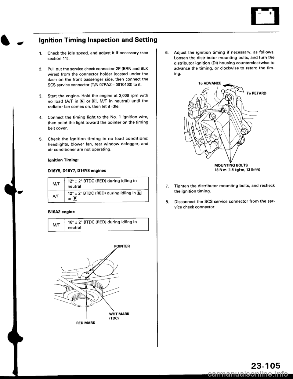
1.Check the idle speed, and adjust it it necessary (see
section 'l '1 ).
Pull out the service check connector 2P (BRN and BLK
wires) from the connector holder located under the
dash on the front passenger side, then connect the
SCS service connector (T/N 07PAZ - 0010'100) to it.
Start the engine. Hold the engine at 3.000 rpm with
no load {A,/T in E or E. M/T in neutral) until the
radiator fan comes on, then let it idle.
Connect the timing light to the No. 1 ignition wire,
then point the light toward the pointer on the timing
belt cover.
Check the ignition timing in no load conditions:
headlights. blower fan, rear window defogger, and
air conditioner are not operating.
lgnhion Timing:
D15Y5. D16Y7, Dl6Yg engines
816A2 engine
MIT16" 12' BTDC (RED) during idling in
neutral
M/T12't 2" BTDC (RED) during idling in
neutral
l2'r 2" BTDC {RED) during idling in S
orE
POINTEB
RED MARK
23-105
ro ADVANCE -<;,
6. Adjust the ignition timing if necessary, as follows.
Loosen the distributor mounting bolts. and turn the
distributor ignition (Dl) housing counterclockwise to
advance the timing, or clockwise to retard the tim-
ing.
MOUNTING BOLTS18 N'm (1.8 kgfm, 13lblftl
Tighten the distributor mounting bolts, and recheck
the ignition timing.
Disconnect the SCS service connector from the ser-
vice check connector.
7.
Page 1576 of 2189
lgnition System
Distributor Replacement
Removal:
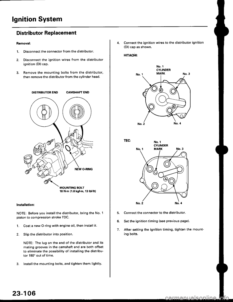
1. Disconnect the connector from the distributor.
2. Disconnect the ignition wires from the distributor
ignition {Dl) cap.
3. Remove the mounting bolts from the distributor,
then remove the distributor from the cylinder head.
DISTRIBUTOR END CAMSHAFT END
MOUNTING BOLT18 N.m 11.8 kgtm, 13lbf.ltl
lnstallation:
NOTE: Before you install the distributor. bring the No. 1
piston to compression stroke TDC.
1. Coat a new O-ring with engine oil, then install it.
2. Slip the distributor into position
NOTE: The lug on the end of the distributor and its
mating grooves in the camshaft end are both offset
to eliminate the possibility of installing the distribu-
tor 180" out of time.
3. Installthe mounting bolts, and tighten them lightly.
23-106
4, Connect the ignition wires to the distributor ignition
(Dl) cap as shown.
rracfit'
No. 1CYLINDERMARK
No. 1CYLINDER
TEG:
5.
6.
7.
No. 2No. a
Connect the connector to the distributor.
Set the ignition timing (see previous page).
After setting the ignition timing, tighten the mount-
ing bolts.