Page 1563 of 2189
Starting System
Component Location Index
A/T GEAR POSITION SW|TCHTest, page 23'154Replacement, page 23-155
STARTER CUT RELAY (M/T}
Test, page 23-86, 87
oo
ool
CLUTCH INTERLOCK
swlTcH
BATTERYTest, page 23-91
STARTERTest, page 23'95Solenoid Test, Page 23 96
Replacement, Page 23-100
Performance Test, Page 23-101
23-93
Page 1566 of 2189

Starting System
Starter Test lcont'dl
Ch€ck tor Wear and Damage
The starter should crank the engine smoothly and
steadily, lf the starter engages. but cranks the engine
erratically, remove it, and inspect the starter drive gear
and torque converter or flywheel ring gear for damage.
. Check the drive gear overrunning clutch for binding
or slipping when the armature is rotated with the
drive gear held,- lf damaged. replace the gears.
Check Cranking Voltsge and Curr€nt Draw
Cranking voltage should be no less than 8.5 volts.
Current draw should be no more than 350 amperes.
lf cranking voltage is too low, or current draw too high,
check for;
. dead or low batterv.
. open circuit in starter armature commutator seg-
ments,
. starter armature dragging.
. shorted armature winding.
o excessive drag in engine.
Check Cranking rpm
Engine speed during cranking should be above 100 rpm,
lf speed is too low, check for:
. loose battery or stanerterminals.
. excessively worn starter brushes,
. open circuit in commutator segments.
o dirty or damaged helical spline or drive gear.
. defective drive gear overrunning clutch.
Check Siarter Disengag€ment
With the shift lever in El or @ position (A/T) or with the
clutch pedal depressed (M/T), turn the ignition switch to
START (lll), and release to ON (ll).
The starter drive gear should disengage from the torque
converter or flywheel ring gear when you release the
Key.
lf the drive gear hangs up on the torque converter or fly-
wheel ring gear, check for:
. solenoid plunger and switch malfunction,
. dirty drive gear assembly or damaged overrunning
clutch.
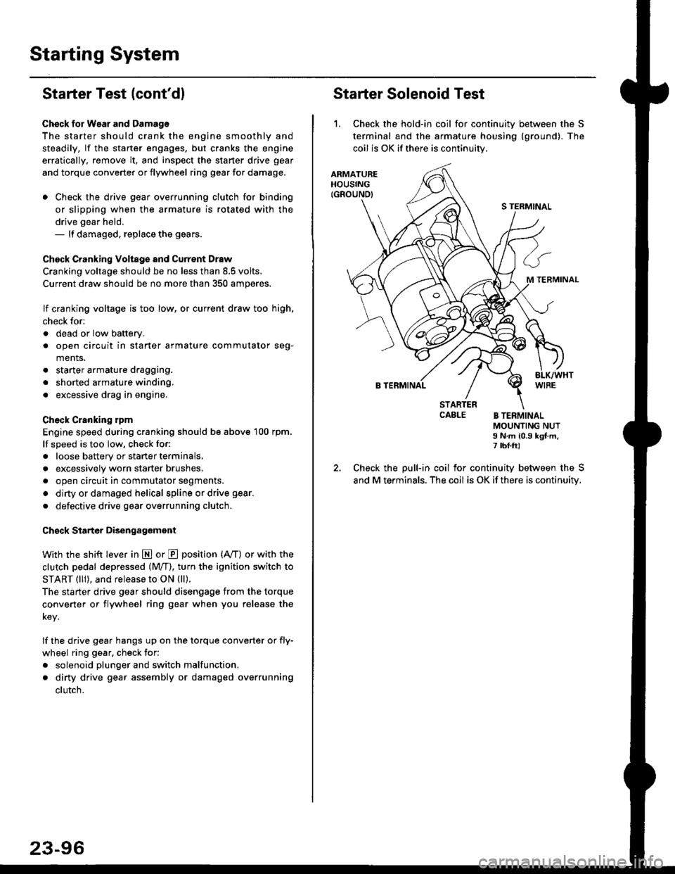
Starter Solenoid Test
1. Check the hold-in coil for continuitv between the S
terminal and the armature housing (ground). The
coil is OK if there is continuitv,
ARMATUREHOUSING(GROUND)
S TERMINAL
M TERMINAL
B TERMINAL
STARTERCAELE B TERMINALMOUNTING NUTI N.m {0.9 kgf.m,7 tbf.ft)
Check the pull-in coil for continuity between the S
and M terminals. The coil is OK if there is continuity.
Page 1567 of 2189
JArmature Inspection and Test
1.Inspect the armature for wear or damage due to con-
tact with the permanent magnet or field winding.
. lf there is wear or damage. replace the armature.
Inspect for damage.
2. Check commutator surface and diameter.
. lf the surface is dirty or burnt. resurface with emery
cloth or a lathe within the following specifications,
or recondition with #500 or #600 sandpaper.
. lf commutator diameter is below the service limit,
replace the armature.
Commutator Diameter
Standard {NEW)Service Limit
28.0 - 28.1 mm
(1.102 - 1.106 in)
27.5 mm
(1.083 in)
VERNIER CALIPEB
3. Measure the commutator runout.
. lf the commutator runout is within the service
limit, check the commutator for carbon dust or
brass chips betlveen the segments.
. lf the commutator runout is not within the ser-
vice limit, replace the armature.
Commutator Runout
Standard (NEW)Service Limit
0 - 0.02 mm(0 - 0.0008 in)
u-u!r mm
(0.002 in)
COMMUTATOR
(cont'd)
23-97
Page 1568 of 2189
Starting System
Armature Inspection and Test (cont'dl
4. Check tor mica depth. lf necessary, undercut mica
with a hacksaw blade to achieve proper depth. l{ ser-
vice limit cannot be maintained, replace the armature.
MICA D€PTH
Commutator Mica D€pth
5. Check for continuity between the segments of the
commutator. lf an open circuit exists between any
segments, replace the armature.
NOT GOOD
Standard (NEW)Service Limit
0.4 - 0.5 mm
(0.016 - 0.02 in)
0.15 mm
(0.006 in)
23-98
corL coFECOMMUTATOR
6. Place the armature on an armature tester. Hold a
hacksaw blade on the armature core.
ARMATURE TESTER
. lf the blade is attracted to the core or vibrates
while the core is turned, the armature is shorted.
Replace the armature.
7. Check with an ohmmeter that no continuity exists
between the commutator and armature coil core,
and between the commutator and armature shaft. lf
there is continuity, replace the armature.
ARMATURE
Page 1569 of 2189

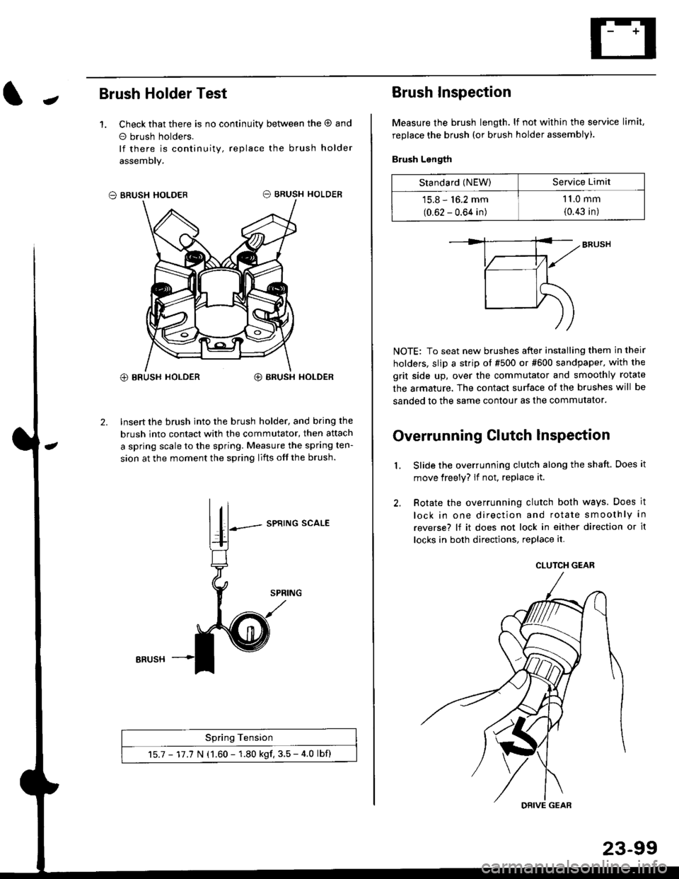
JBrush Holder Test
1. Check that there is no continuity between the O and
o brush holders.
lf there is continuity, replace the brush holder
assemoly.
O BRUSH HOLDER
@ BRUSH HOLDER€) BRUSH HOLDER
2. Insert the brush into the brush holder, and b.ing the
brush into contact with the commutator, then attach
a spring scale to the spring. Measure the spring ten-
sion at the moment the spring lifts off the brush.
SPRING SCALE
Spring Tension
15.7 - 17.7 N (1.60 - 1.80 kgf. 3.5 - 4.0 lbf)
ERUSH
Brush Inspection
Measure the brush length. lf not within the service limit,
replace the brush (or brush holder assembly).
Brush Length
NOTE: To seat new brushes after installing them in their
holders, slip a strip ot #500 or #600 sandpaper. with the
grit side up, over the commutator and smoothly rotate
the armature. The contact surface of the brushes will be
sanded to the same contour as the commutator.
Overrunning Clutch lnspection
Slide the overrunning clutch along the shaft. Does it
move freely? lf not, replace it.
Rotate the overrunning clutch both ways. Does it
lock in one direction and rotate smoothly in
reverse? lf it does not lock in either direction or it
locks in both directions, replace it.
2.
L
Standard (NEW)Service Limit
15.8 - 16.2 mm
(0.62 - 0.64 in)
1 1.0 mm
{0.43 in)
CLUTCH GEAR
DRIVE GEAR
Page 1570 of 2189

Starting System
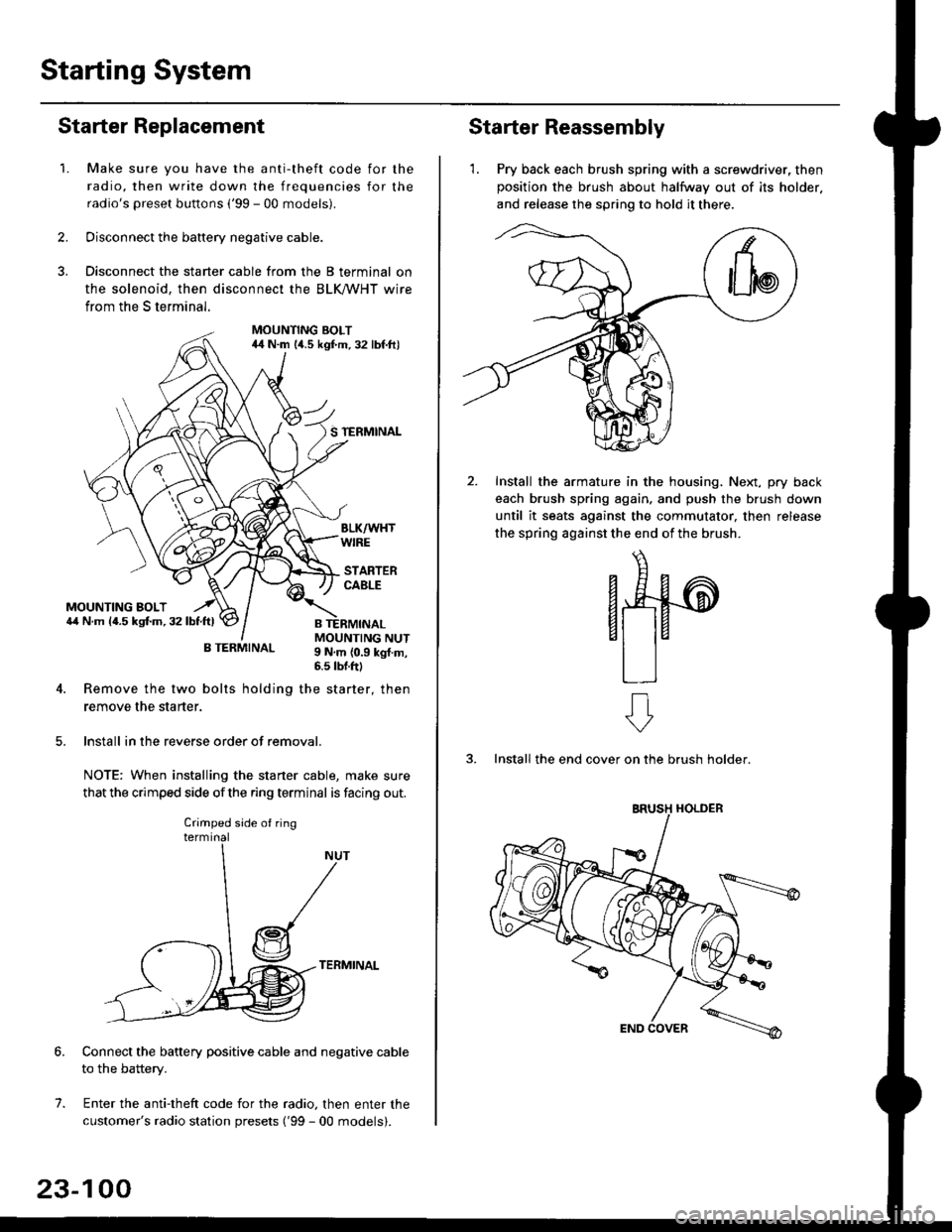
Starter Replacement
1.Make sure you have the anti-theft code for the
radio, then write down the frequencies for the
radio's preset buttons ('99 - 00 models).
Disconnect the battery negative cable.
Disconnect the starter cable from the B terminal on
the solenoid, then disconnect the BLK trHT wire
from the S terminal.
MOUNTING BOLT44 N.m l/t.s kgf.m. 32 lbf.ft)
S TERMINAL
MOUNTING BOLT6,1 N.m {4.5 kstm.32lbtftl
MOUNTING NUT9 N,m {0.9 kgl.m,6.s lbtftl
B TERMINAL
4. Remove the two bolts holding the starter, then
remove the starter.
lnstall in the reverse order of removal.
NOTE: When installing the staner cable, make sure
that the crimped side ofthe ring terminal is facing out.
TERMINAL
Connect the battery positive cable and negative cable
to the battery.
Enter the anti-theft code for the radio, then enter the
customer's radio station presets ('99 - 00 models).
7.
Crimped side of ring
23-100
Starter Reassembly
'1. Pry back each brush spring with a screwdriver, then
position the brush about halfway out of its holder.
and release the spring to hold it there.
Install the armature in the housing. Next, pry back
each brush spring again, and push the brush down
until it seats against the commutator, then release
the spring against the end of the brush.
aw
3. Install the end cover on the brush holder.
ERUSH HOLDER
Page 1572 of 2189
lgnition System
Component Location Index
IGNITION TIMING CONTROL SYSTEM
. Troubleshooting, section 11
. ldle speed Inspection/Adjustment. section 11
. Inspection and Setting, page 23-105
SERVICE CHECK CONNECTOR {2P}Iwiie colors: 8RN and BLKI
TEST TACI{OMETER CONNECTOB
IGNITION WIRESlnspection and Test, page 23-110
PLUGSInspection, page 23 1 11
Replacement, page 23'106Overhaul, page 23-107lgnition Coil Test, page 23'110lgnition Control Module llCM)Input Test, page 23-109
23-102
Page 1576 of 2189

lgnition System
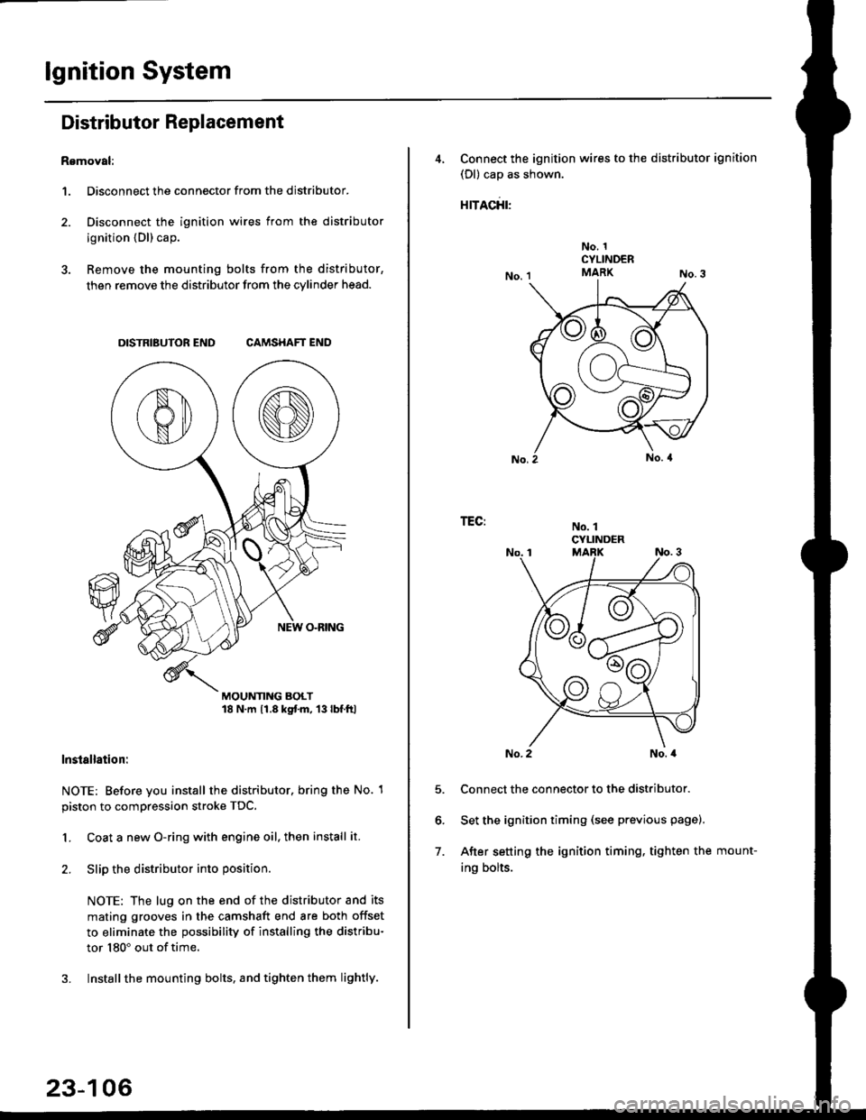
Distributor Replacement
Removal:
1. Disconnect the connector from the distributor.
2. Disconnect the ignition wires from the distributor
ignition {Dl) cap.
3. Remove the mounting bolts from the distributor,
then remove the distributor from the cylinder head.
DISTRIBUTOR END CAMSHAFT END
MOUNTING BOLT18 N.m 11.8 kgtm, 13lbf.ltl
lnstallation:
NOTE: Before you install the distributor. bring the No. 1
piston to compression stroke TDC.
1. Coat a new O-ring with engine oil, then install it.
2. Slip the distributor into position
NOTE: The lug on the end of the distributor and its
mating grooves in the camshaft end are both offset
to eliminate the possibility of installing the distribu-
tor 180" out of time.
3. Installthe mounting bolts, and tighten them lightly.
23-106
4, Connect the ignition wires to the distributor ignition
(Dl) cap as shown.
rracfit'
No. 1CYLINDERMARK
No. 1CYLINDER
TEG:
5.
6.
7.
No. 2No. a
Connect the connector to the distributor.
Set the ignition timing (see previous page).
After setting the ignition timing, tighten the mount-
ing bolts.