Page 709 of 2189

L
E Position
The flow of fluid through the torque convefter circuit is the same as in E position The line pressure (1) changes to the
line pressure (3) and flows to the l-2 shift valve. The iine pressure (3) changes to the line pressure (3') at the 'l-2 shift valve
and flows to the servo valve. The servo valve is moved to the right side (Reverse range position) and uncovers the port to
allow line pressure {3") to the manual valve, The line pressure {3') from the 1-2 shift valve flows through the servo valve to
the manual valve and changes the 4th clutch pressure (40). The 4th clutch pressure (40) is applied to the 4th clutch, and
the 4th clutch is engaged,
Reverse Inhibitor Control
When the E position is selected while the vehicle is moving forward at spe€ds over 6 mph (10 km/h)' the PCM outputs the
1st speed signal to shift control solenoid valves A and B; shift control solenoid valve A is turned oFF, shift control solenoid
valve B is turned ON. The 1-2 shift valve is moved to the right side and covers the port to stop line pressure (3') to the
servo valve. The line pressure (3'�) is not applied to the servo valve, and the 4th clutch pressure (40) is not applied to the
4th clutch, as a result, power is not transmitted to the reverse direction'
When used. 'left" or "right" indicates direction on the hydraulic circuit'
14-31
Page 712 of 2189

Description
Lock-up System (cont'd)
TOROUE CONVERTER
In B.rl position, in 3rd and 4th, and lDl_- position in 3rd.pressurized fluid is drajned from the back of the torqueconverter through a fluid passage. causing the lock-uppiston to be held against the torque convener cover. Asthis takes place, the mainshaft rotates at the same speedas the engine crankshaft, Together with the hydrauliccontrol, the PCM optimized the timing of the lock_upsystem. Under certain conditions, the lock_up clutch isapplied during deceleration, in 3rd and 4th gear.
The lock-up system controls the range of lock_up accord_ing to lock-up control solenoid valves A and B. and thelinear solenoid. When lock-up control solenoid valves Aand B activate, modulator pressure changes. Lock_upcontrol solenoid valves A and B and the linear solenoidare mounted on the outside of the torque converterhousing. and are controlled by the pclvl.
Lock-up Conditions/Lock-up Control Solenoid Valves/Linear Solenoid Pressure
MODULATOR PRESSURE
.-- LINEAR SOLENOID PRESSURE
LOCK.UP CONTROL. VALVE
LOCK.UP CONTROLSOLENOID VALVELock-up
Conditions
Lock-up Control
Solenoid ValveLineal
Solenoid
PressureAB
Lock-up OFFOFFOFFHig h
Lock-up. HalfONDuty operation
OFF - ON
Lock-up. FullONONHigh
Lock-up
during
decelerationONDuty operation
OFF * ONLowTOROUE CONVERTERCHECI( VALVE
RELIEF VAI-VE
LOCK.UP TIMINGVALVE
^ r______rr r cooLER RELTEF VALVE
t'-
14-34
ATF PUMP
Page 713 of 2189
I
TOROUE CONVERTER
No Lock-up
. Lock-up Control Solenoid Valve A: OFF
. Lock-up Control Solenoid Valve B: OFF
. Linear Solenoid Pressure: High
The pressurized fluid regulated by the modulator works
on both ends of the lock-up shift valve. Under this condi-
tion, the pressures working on both ends of the lock-up
shift valve are equal, the lock-up shift valve is moved to
the right side by the tension of the valve spring alone.
The fluid from the ATF pump will flow through the left
side of the lock-up clutch to the torque convener; that is,
the lock-up clutch is in OFF condition.
NOTE: When used, "left" or "right" indicates direction
on the hydraulic circuit.
MOOULATOR PRESSURE
LINEAR SOLENOIO PRESSURE
(cont'd)
LOCK.UP CONTROLSOLENOID VALVE
RELIEF VALVE
LOCK-UP TIMINGVALVE
9 L ] I COOLER RELIEF VALVE
ATF PUMP
14-35
Page 714 of 2189

Description
Lock-up System (cont'dl
TOROUE CONVERTER
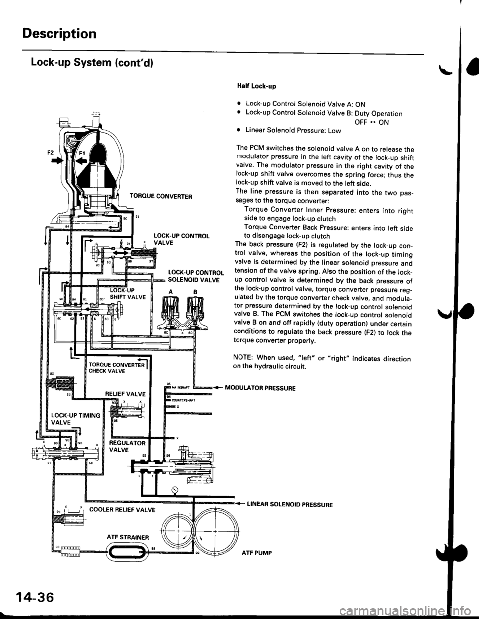
Half Lock-up
. Lock-up Control Solenoid Valve A: ONLock-up Control Solenoid Valve 8: Duty Operation
OFF - ONLinear Solenoid Pressure: Low
The PCM switches the solenoid valve A on to release themodulator pressure in the left cavity of the lock_up shiftvalve. The modulator pressure in the right cavity of thelock-up shift valve overcomes the spring force; thus thelock-up shift valve is moved to the left side.The line pressure is then separated into the two pas-sages to the torque converter:
Torque Converter Inner pressure: enters into rightsade to engage lock-up clutch
Torque Converter Back pressure: enters into left sideto diseogage lock-up clutchThe back pressure (F2) is regulated by the lock-up con-trol valve, whereas the position of the lock-up timingvalve is determined by the linear solenoid Dressure andtension of the valve spring. Also the position of the lock_up control valve is determined by the back pressure ofthe lock-up control valve, torque converter pressure reg_ulated by the torque converter check valve, and modula_tor pressure determined by the lock-up control solenoidvalve B. The PCM switches the lock-up control solenoidvalve B on and off rapidly {duty operation} under certainconditions to regulate the back pressure (F2) to lock thetorque convener properly.
NOTE: When used, "left" or "right" indicates directionon the hvdraulic circuit.
MODULATOR PRESSURE
LINEAR SOLENOTD PRESSURE
LOCK.UP CONTROLVALVE
LOCK.UP CONTROLSOI.TNOID VALVE
A8
TOROUE CONVERTERCHECK VAI-VE
RELIEF VALVE
LOCK-UP TIMINGVALVE
^ L____J'r cooLER RELTEF valvE
14-36
ATF PUMP
Page 715 of 2189

TOROUE CONVERTER
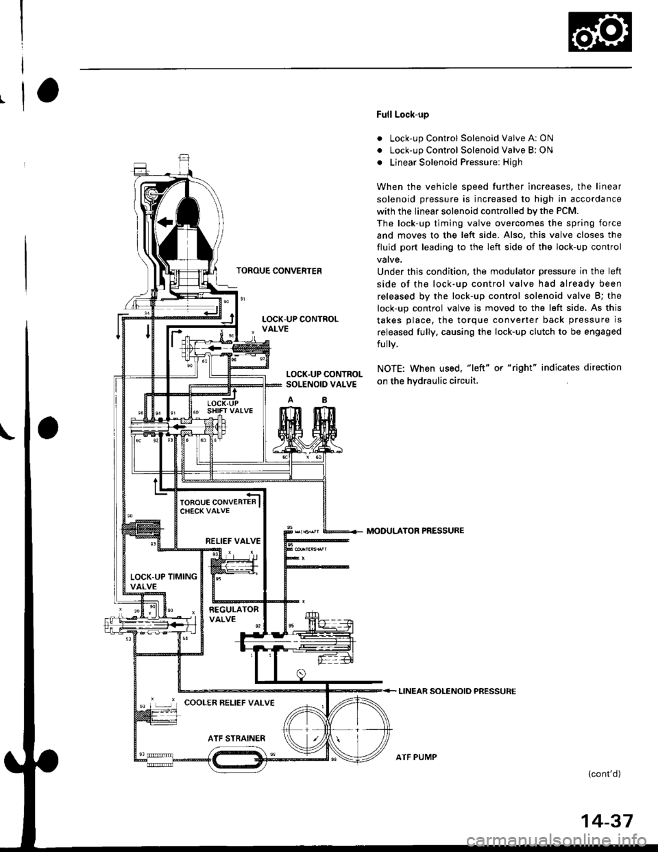
Full Lock-up
. Lock-up Control Solenoid Valve A: ON
. Lock-up Control Solenoid Valve B: ON
o Linear Solenoid Pressure: High
When the vehicle speed further increases. the linear
solenoid pressure is increased to high in accordance
with the linear solenoid controlled bv the PCM.
The lock-up timing valve overcomes the spring force
and moves to the left side. Also, this valve closes the
fluid port leading to the left side of the lock-up control
Under this condition. the modulator pressure in the left
side of the lock-up control valve had already been
released by the lock-up control solenoid valve B; the
lock-up control valve js moved to the left side. As this
takes place, the torque converter back pressure is
released fully. causing the lock-up clutch to be engaged
fully.
NOTE: When used, "|eft" or "right" indicates direction
on the hvdraulic circuit.
MODULATOR PRESSURE
LINEAR SOLENOIO PRESSURE
{cont'd)
LOCK.UP CONTROLSOLENOID VALVE
RELIEF VALVE
LOCK.UP TIMINGVALVE
'r ,-.r' cooLER RELTEF vALvE
ATF PUMP
14-37
Page 716 of 2189
Description
Lock-up System (cont'dl
TOROUE CONVERTER
Deceleration Lock-up
. Lock-up Control Solenoid Valve A: ON. Lock-up Control Solenoid Valve B: Duty Operation
OFF - ONa Linear Solenoid Pressure: Low
The PCM switches solenoid valve B on and off rapidly
under certain conditions. The slight lock-up and half
lock-up regions are maintained so as to lock the torque
converter properly.
NOTE: When used, "left" or "right" indicates direction
on the hydraulic circuit,
MOOULATOR PRESSURE
LINEAR SOLENOID PRESSURE
LOCK-UP CONTROLSOLENOID VALVE
RELIEF VALVE
LOCK.UP TIMINGVALVE
COOLER RELIEF VALVE
ATF STRAINER
1434
ATF PUMP
Page 752 of 2189

Electrical Troubleshooting ('96 - 98 Models)
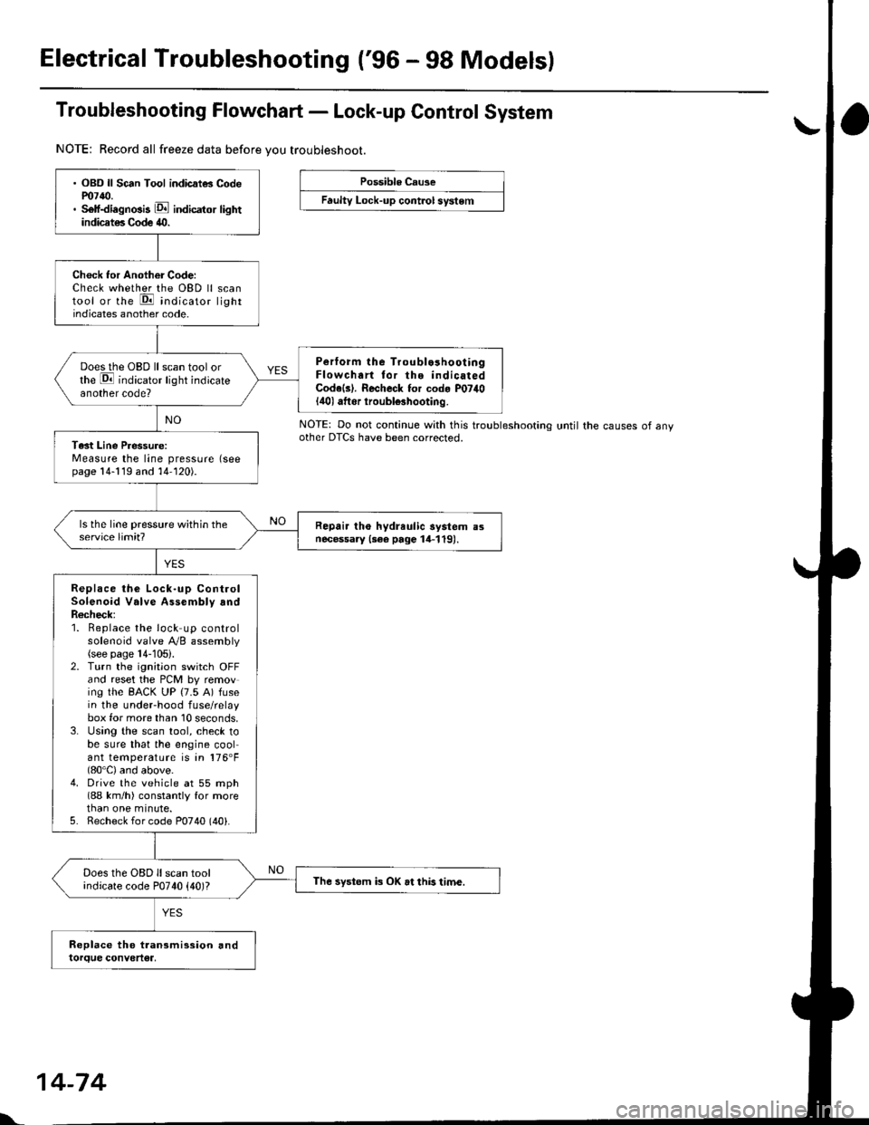
Troubleshooting Flowchart - Lock-up Control System
NOTE: Record all freeze data before vou troubleshoot.
Possible Cause
Faulty Lock-up cont.ol system
NOTE: Do not continue with this troublesnoonnoother DTCS have been corrected.until the causes of any
. OBD ll Sc6n Tool indicatG Codem7{0.. Self-diagnosis E indicator lightindicates Code 40.
Check tor Another Code:Check whether the OBD ll scantool or the E indicato, lightindicates another code.
Perform lhe Troublo3hooiingFlowchart tor the indicatedCode(s). Recheck for cod. P07il0lilol aftor iroubl€3hooting.
Does the OBD ll scan tool orthe E indicator light indicateanother code?
Tast Line Pressure:Measure the line pressure (seepage 14-119 and 14-120).
Repair tho hydreulic aystem a3necessary {3ee page 14-119).
Replace the Lock-up ControlSolenoid Valve Assembly andR6check;1. Beplace the lock up controlsolenoid valve Ay'B assembly(see page 14-105).2. Turn the ignitaon switch OFFand reset the PCM by removing the BACK UP (7.5 A) fusein the underhood fuse/relaybox for more than 10 seconds,3. Using the scan tool, check tobe sure that the engine coolant temperature is in 176'F(80'C) and above.4. Drive the vehicle at 55 mph(88 km/h) constantly for morethan one minute.5. Recheck for code P0740 (40).
Does the OBD ll scan toolindicate code P0740 {40)?The systom k OK at this time.
l'.
14-74
Page 753 of 2189

Troubleshooting Flowchart - Shift Control System
NOTE: Record all freeze data before vou troubleshoot.
Possible Cause
Faulty shift control system
. OBD ll Scan Tool indicates CodeP0730.. Sell-diagnosis E indicator
light indicates Code ill.
Check tor Another CoderCheck whether the OBD ll scantool or the E, indicator lightindicate another code.
Perlorm ths TroubleshoolingFlowch.rt for the indic.t.dCode(sl. Recheck tor code m730
l4'l I atter troubleshooting.
Does the oBD ll scan tool orthe E indicato'. tight indicate another code?
Test lst, 2nd, 3rd and 4th Clutch
Pressure:Measure the 1st, 2nd, 3rd and 4th
clutch pressure (see page 14119
thru 14-121).
Ropair the hydrlulic systom !snecessary {see page 14-1 19 and11-1211.
ls each clutch pressure within
the service limit?
Replace Shift Control Solenoidvalve Assembly, Linear SolenoidAssambly and Rechock:1. Replace the shift controlsolenoid valve A'/B assembly(see page 14-106).2. Replace the linear solenoidassembly lsee page 14 108).3. Turn the ignition switch OFFand reset the PCM memory byremoving the EACK UP (7.5 A)tuse in the under hood fuse/relay box for more than l0
seconds,4. Drive the vehicle at over 12mph (20 km/h) in 1st, 2nd,3rd
and 4th gear for more than 30seconds at P1 position.
5. Recheck tor code P0730 (41).
Does the OBD ll scan tool orthe Ed indicator tight indi
cate code P0730 {41)?
The swt6m is OK et this time.
NOTE: Do not continue with this troubleshooting until the causes ot any
other DTCS have been corrected.