Page 234 of 2189
Oil Filter
Replacement
After the engine has been run, the exhaust pipe willbe hot; be careful when working around ihe exhaustpipe.
Be careful when loosening the drain bolt whils theengine is hot. Burns can resuh because the oil tem-peratu16 is very high.
Remove the oil filter with the oil filter wrencn.
Inspect the threads and rubber seal on the new filter.Wipe off the seat on the engine block, then apply alight coat of oil to the new filter,s rubber seal.
NOTE: Use onty fitters with a built-in bypass sys,tem.
Apply oil to rubber sealbefore installing.
l.
Inspect threads andrubber seal surface.
8-8
Install the oil filter by hand.
After the rubber seal seats, tighten the oil filter clock_wise with the oil filter wrench.
Tighten: 7/8 tu.n clockwise.
Tightening tolque: 22 N.m (2.2 kgt.m, 16lbf.ft)
OIL FILTER WRENCH07912 - 6110001
Page 235 of 2189

Oil Pressure
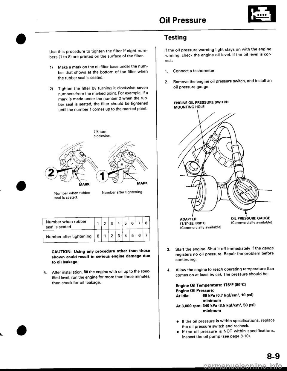
Use this procedure to tighten the filter if eight num-
bers (1 to 8) are printed on the surface of the filter.
1) Make a mark on the oil filter base under the num-
ber that shows at the bottom of the filter when
the rubber seal is seated.
2l Tighten the filter by turning it clockwise seven
numbers from the marked point. For example, if a
mark is made under the number 2 when the rub
ber seal is seated, the filter should be tightened
until the number 1 comes up to the marked point'
7/8 turn
Number when rubDer
seal is seated
Number after tightening.
CAUTION: Using any procedure other than those
shown could rosult in serious engins damage due
to oil leakage
5. After installation. fill the engine with oil up to the spec-
ified level, run the engine for more than three minutes,
then check for oil leakage
MARK
Number when rubber
seal is seated578
Number after tightening8151
Testing
lf the oil pressure warning Iight stays on with the engine
running, check the engine oil level. It the oil level is cor-
rect:
1. Connect a tachometer'
2. Remove the engine oil pressure switch, and install an
oal pressure gauge.
ENGINE OtL PRESSURE SWITCH
MOUNTING HOLE
ADAPTER(1/8\28. BSPTI
{CommerciallY availablei
Start the engine. Shut it off immediately if the gauge
registers no oil pr€ssure. Repair the problem before
continuing.
Allow the engine to reach operating temperature (tan
comes on at least tlivice). The pressure should be;
Engine Oil Temperature: 176"F (80"C1
Engine Oil Pressulo:
At ldle: 69 kPa (0.7 kgf/Gm'�. 10 Psi)
minimum
At 3.000 rpm: 3/Ut kPa (3.5 kgt/cm'�, 50 psi)
minimum
. lf the oil Dressure is within specifications, replace
the oil pressure switch and recheck.
. lf the oil pressure is NOT within specifications,
inspect the oil pump (see page 8-10).
OIL PRESSURE GAUGE(Commerciallv available)
8-9
Page 237 of 2189
Oil Pump
Overhaul
NOTE:
. Use new O rings when reassembllng.
. Apply oil to O-rings before installation.
. Use liquid gasket, Part No. 08718 - 0001 or 08718 - 0003
. The rotors must be installed to the same direction in order'
o After reassembly, check that the rolors move without binding'
B15A2 engine:
6x1.0mm7 N.m (0.7 kgf m, 5 lbf ft)
OUTER ROTORInspection, page 8-13
INNER ROTORpage 8-13
OOWELPIN
O-RINGReplace.
6x1.0mm11 N.m (1.1
8 tbtfrlkgf.m,
PUMP HOUSINGInspection, page 8-13
Apply liquid gasket
to the mating surface of
the cylinder blockwhen installing.
8 x 1.25 mm24 N,m {2.i1 kgl.m.
17 tbf.ft)RELIEF VALVEValve mlst slide freeiy
in housing bore.Replace if scored.OIL SEALReplace.lnstallation,page 8-14
SEALING BOLT39 N.m l4O kgt'm,29 tbt frl
\(cont'd)
SPRING
8-11
Page 238 of 2189
Oil Pump
Overhaul (cont'dl
NOIE:
. Use new O rings when reassembling.. Apply oil to O rings before instalraUon.. Use liquid gasket, Parr No. 08718 - 0001 or08718_0003.. The rotors must be installed to the same direction.. After reassembly, check that the rotors move without binding.
D16Y5, D16Y7, D16Y8 engines:
(
6x1.0mm7 N.m (0.7 kgI.m, 5 lbf ftl
PUMP HOUSINGInspection, page 8 13Apply liquid gasketto mating surface ofthe cylinder biockwhen installing.
INNER ROTORInspectron, page 8 13
DOWEL PIN
PUMP COVEB
O-RING
_.feor,""
\6x1.0mm11 N.m {1.1 kgf.m,8lbl.ft)RELIEF VALVEValve must slide freelyin housing bore.Replace if scored
OIL SEAL
[".?li;:;"". *,", ,.rg
""rc
@.-*or"."
9''ggttt*
8-12
Page 240 of 2189

Oil Pump
RemovaUlnspection/lnstallation (cont'dl
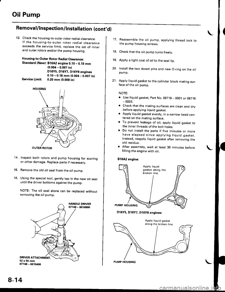
13. Check the housing-to-outer rotor radial clearance.lf the housing-to-outer rotor radial clearanceexceeds the service limit, replace the set of innerand outer rotors and/or the pump housing.
Housing-to-Outer Rotor Badial Clearanco:Standard {Newl: 816A2 sngine 0.10 - 0.19 mm(0.004 - 0.007 in)
D16y5, Di6y7, Dt6y8 engines0.10 - 0.18 mm {0.00it _ 0.007 in)Service Limit: 0.20 mm (0.008 in)
lnspect both rotors and pump housing for scoringor other damage. Replace parts if necessary.
Remove the old oil sealfrom the oil pump.
Using the special tool, gently tap in the new oil sealuntil the driver bottoms against the pump.
NOTE: The oil seal alone can be replaced withoutremoving the oil pump.
DRIVER ATT52x55mm077a6 - 0010ao0
14.
15.
16.
8-14
PUMP HOUSING
17. Reassemble the oil pump, applying thread lock tothe pump housing screws.
18. Check that the oil pump turns freely.
19. Apply a light coat of oilto the seal lip.
20. Install the two dowel pins and new O-ring on the oilpump.
21. Apply liquid gasket to the cylinder block mating sur_face of the oil pump.
NOTE:
. Use liquid gasket, Part No.08718 - oOOj or 08718- 0003.. Check that the mating surfaces are clean and drybefore applying liquid gaskel. Apply liquid gasket evenly, in a narrow bead cen-tered on the mating surface.o To prevent leakage of oil, apply liquid gasket tothe inner threads of the bolt holes.. Do not install the parts if five mtnures or morehave elapsed since applying liquid gasket.Instead. reapply liquid gasket after removing theold residue.
. After assembly, wait at least 30 minutes beforefilling the engine with oil.
81642 engine:
\
D16Y5, D16Y7, D16Y8 engines:
along the broken line.
Page 241 of 2189
22. Installthe oil pump on the cylinder block.
Apply grease to the lip ot the oil pump seal.
Then. install the oil pump onto the crankshaft.
When the pump is in place, clean any excess grease
off the crankshaft and check that the oil seal lip is
not distorted.
81642 engine:
8 x 1.25 mm6x1.Omm
24 N.m (2.i4 kg[.m,17 tbl.trl
11 N.m {1.1 kg{.m,8 rbt ft)O.RI GReplace.
DOWEL PINS
GASKETReplace.
OIL SCREEN
6x1.0mmrl N.m {1.1 kgf'm,I tbf.ftl
D16Y5, D16Y7. D16Y8 enginos:
OOWEL PIN
6x1.0mm11N'm (1.1 kgf m'
O.RINGReplace.
DOW€L PIN
GASKETReplace.
6x1.0mm
6 x 1.0 mm '11 N'm {1 1 kgf'm,
11 N.m (1.1 kgf.m, I lbf ftl
8 lbf.ft)
!o
8-15
lnstall the oil screen.
Install the oil pan (see pages 7-26 or 7-27).
NOTE: Clean the oil pan gasket mating surfaces.
Page 264 of 2189
Cap Testing
1. Remove the radiator cap, wet its seal with engine
coolant, then install it on the pressure tester'
RADIATOR PR€SSURE TESTER(CommerciallY available)
RAOIATOR
(for 32 mm neck' low Pro{ile)
Apply a pressure of 93 - 123 kPa (0.95 - 'l 25 kgflcm'�'
14 - 18 psi).
Check for a drop in Pressure.
lf the pressure drops, replace the cap
I
t
ADAPTOR
Testing
LWait until the engine is cool, then carefully remove
the radiator cap and fill the radiator with engine
coolant to the top of the tiller neck
Attach the pressure tester to the radiator and apply
a pressure of 93 - '123 kPa (0.95 - 1.25 kgflcm'�, 14 -
18 psil.
RADIATOR PRESSURE
TESTER
lCommerciallY available)
ADAPTOR(for 32 mm neck, low Profile)
Inspect for engine coolant leaks and a drop In pres-
sure.
Remove the tester and reinstall the radiator cap
NOTE: Check for engine oil in the coolant and/or
coolant in the engine oil.
10-9
Page 269 of 2189
Water Pump
Inspection
't.
2.
Remove the timing belt (see section 6).
Turn the water pump pulley counterclockwise.Check that it tarns freely.
Check for signs of seal leakage.
NOTE: A small amount of "weeping,,from the bleedhole is normal.
Dl6Y5, Dl6Y7, D16Y8 engines:
BLEEDHOLE
B16A2 engine:
BLEED HOLE
BLEED HOLE
BLEED HOLE
10-14
Replacement
6x1.0mm
1.Remove the timing belt (see section 6).
Remove the water pump by removing five bolts.
NOTE: Inspect, repair and clean the O-ring grooveand mating surface with the cylinder block.
D16Y5, D16Y7, D16Y8 engines:
12 N.m {1.2 kgf.m, l0 x 1.25 mm8.7 lbt.ft) {4 N.m 14.5 kg{.m.33 tbt.ft)
Bl642 engine:
WATERPUMP
@;2
6x1.0mm12 N.m 11.2 kg{.m,8.7 tbf.ft)
O.RINGReplace.
3. Install the water pump in the reverse order of removal.
NOTE:
o Keep the O-ring in position when installing.. Clean the spilled engine coolant.
d
orp,
I