Page 1129 of 2189
?
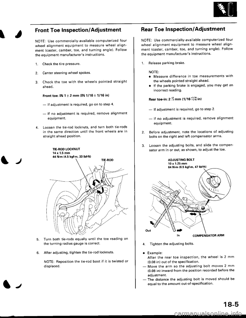
Front Toe Inspection/Adiustment
NOTE: Use commercially-available computerized four
wheel alignment equipment to measure wheel align-
ment (caster, camber, toe, and turning angle). Follow
the equipment manufacturer's instructions.
1. Check the tire pressure.
Center steering wheel spokes.
Check the toe with the wheels pointed straight
a head.
Front toe: lN 1 1 2 mm llN l/16 r 1/16 inl
- lf adjustment is required, go on to step 4.
- lf no adjustment is required, remove alignment
equrpmenr.
Loosen the tie-rod locknuts, and turn both tie-rods
in the same direction until the front wheels are in
straight ahead position.
TIE.ROD LOCKNUT'14 x 1.5 mm
4.
tJ
6.
Turn both tie-rods equally until the toe readang on
the turning radius gauge is correct.
After adjusting, tighten the tie-rod locknuts.
NOTE: Reposition the tie-rod boot if it is twisted or
displaced.
4,1 N.m {4.5 kgf.m, 33 lb{.ft)
2.
Rear Toe Inspection/Adiustment
NOTE: Use commercially-available computerjzed Iour
wheel alignment equjpment to measure wheel align-
ment (caster, camber, toe, and turning angle). Follow
the equipment manufacturer's instructions.
1. Release parking brake.
NOTE:
a Measure difference in toe measurements wlth
the wheels pointed straight ahead.
. if the parking brake is engaged, you may get an
incorrect readang,
Rear toe-in: 2 11 mm ttltollllS int
- lf adjustment is required, go to step 2.
- lf no adjustment is required, remove alignment
equipment.
Before adjustment, note the locations of adiusting
bolts on the right and left compensator arms
Loosen the adjusting bolts, and slide the compen
sator arm in or out. as shown, to adjust the toe
ADJUSTING BOLT10 x 1.25 mm
In CoMPENSAToR ARM
4. Tighten the adiusting bolts
. Example:
After the rear toe inspection, the wheel is 2 mm
(0.08 in) out of the specification.- Move the arm so the adjusfing bolt moves 2 mm
(0.08 in) inward trom the position recorded before the
adjustment.- The distance the adjusting bolt is moved should be
equal to the amount out-of-specification.
64 N.m 16.5 ksf m, 47 lbtft)
18-5
Page 1136 of 2189
Front Suspension
Knuckle/Hub Replacement (cont'dl
NOTE: Use the special tool to separate the ball joints
from the suspension or steering arm,
CAUTION: 86 careful not lo damage the ballioint boot.
12. Clean any din or grease off the ball joint.
13. Remove the cotter pin from the steering arm, and
remove the nut.
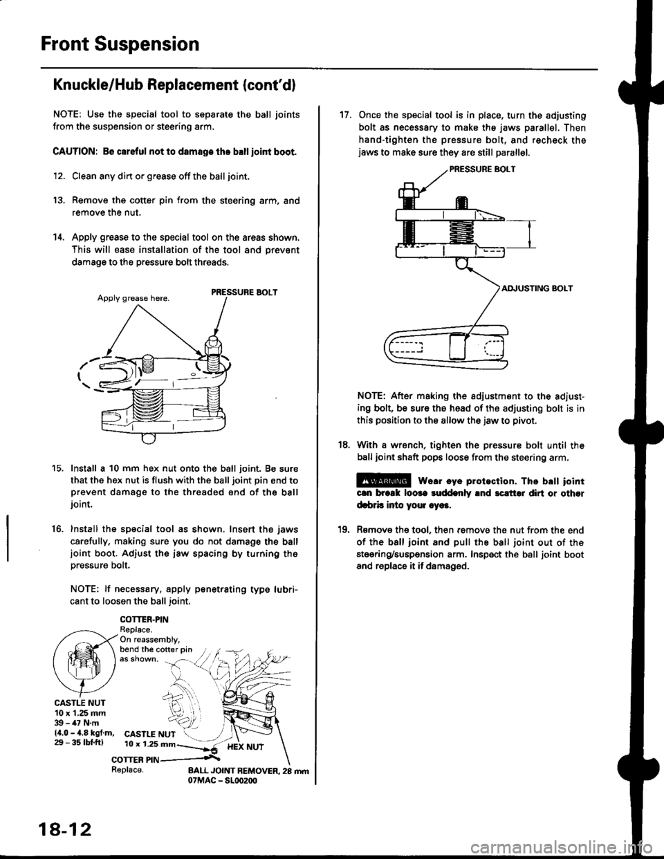
14. Apply grease to the special tool on the areas shown,
This will ease installation of the tool and prevsnt
damage to the pressure bolt threads.
PRESSURE AOLT
Install a 10 mm hex nut onto the ball joint. Be sure
that the hex nut is flush with the ball joint pin end toprevent damage to the threaded end of the balljoint.
Install the special tool as shown. Insert the jaws
carefully, making sure you do not damage the balljoint boot. Adiust the iaw spacing by turning th6pressure bolt.
NOTE: lf necessary, apply penetrating type lubri-
cant to loosen the ball joint.
COTTER.PINReplace.On reassembly,bend the cofter pin
15.
16.
CASTI.T NUT10 x 1,25 mm39 - 47 N.m14.0 - 4.8 kgf.m,29 - 3s tbl.fttCASTLE NUT10 r 1.2s mn--]*-
corrcn nn .\
18-12
Replace-
17. Once the special tool is in place, turn ths adjusting
bolt as necessary to make the jaws parallel. Then
hand-tighten the pressure bolt, and recheck thejaws to make sure they are still parallel.
AI\IUSTING BOLT
NOTE: After making the adiustment to the adiust-
ing bolt, be sure the head of the adjusting bolt is in
this position to the allow the jaw to pivot.
With a wrsnch, tighten the pressure bolt until the
ball joint shaft pops loose from the steering arm.
E@ we.r cye plotection. Thc brtt iointcln brcrk loose suddenly and sclt'tol dirt or other
d.brb inio youl .ye..
Rsmov€ the tool, then remove th€ nut from the end
of the ball ioint and pull the ball joint out of the
stoering/suspension arm. Insp€ct the ball joint boot
and replace it if damaged.
18.
10
Page 1284 of 2189
Moonroof
Motor, Drain Tube and Frame Replacement
CAUTION:
. Put on gloves to protecl your hands.
. Be careful not to damage the seats, dashboard and other interior trim.
'1. Remove the headliner {see page 20-64).
2. Disconnect the motor connector and glass position switch connector.
NOTE: When removing the motor, detach the connector from the frame, remove the bolts and nuts, then remove the
motor.
3. Remove the glass {see page 20-52).
4. Disconnect the drain tubes, and detach the ceiling light harness.
5. Remove the frame mounting bolts.
NOTE;
. An assistant is helpful when removing the bolts.
. Remove the front bolts last.
6. Detach the rear hooks by moving the frame forward, then remove the frame.
BOLT6x1.0mm9.8 N.m {1.0 kgt m,7.2 tht.hl
6x1.0mm9.8 N m (1.0 kgl.m, 7.2 lbtft)
20-54
\
Page 1286 of 2189
Moonroof
1.
2.
Switch Plate Adjustment (Fully Closed Positionl
3.
4.
5.
Remove the headliner {see page 20-64).
Using the moonroof wrench, close the glass fully.
NOTE: Check the glass fit to the rool panel.
Using an open-end wrench, loosen the switch plate mounting bolts.
Adjust position of the switch plate (switch cam) as shown.
Check the operation of the glass (from tilt-up position to fully closed position, from the fully open position to the fully
closed position) by operating the moonroof switch.
NOTE: Check the glass height (see page 20-51).SWITCH PLATE
GUIDEPLATE
SWITCH CAM
While moving the switch plateplate at the position where thea (a faint click is heard).
INNER CABLE END
little bv little, secure the switchswitch cam contacts the switch
Close the glass fully, and check for water leaks.
NOTE: Do not use high-pressure water.
CAELE BRACKET
20-56
Page 1294 of 2189
Headliner
Replacement
CAUTION: When prying with a flat-tip screwdriver,
wrap it with proioctiva tap€ to prevsnt damage.
NOTE:
. Take care not to bend and scratch the headliner.
. Be careful not to damage the dashboard and other
interior trim.
'1. Remove:
4D:
. Front pillar trim (both sides. see page 20-59)
. Center pillar lower trim panel (both sides, see page
20 59)
Upper anchor bolt from the front seat belt (both
sides, see page 20-85)
Center pillar outer trim and center pillar upper trim
(both sides, see page 20-59)
Ceiling light (see section 23)
Rearview mirror (see page 20-25)
a
a
a
a
a
3D:
. Front pillar trim (both sides, see page 20-60)
. Right rear seat-back and rear seat cushion (see
page 20-80)
. Rear center shelf (see page 20-60)
. Rear side shelf and side trim panel (right side,
see page 20-60)
. Upper anchor bolts from the front and rear seat
belts (right side. see pages 20-86, 89)
. Ouarter trim panel (right side, see page 20-60)
. Ceiling light (see section 23)
. Rearview mirror (see page 20-25)
2Dl
. Front pillar trim (both sides, see page 20-51)
. Right rear seat-back and rear seat cushion (see
page 20-81)
Side trim panel (right side, see page 20-61)
Upper anchor bolt from the front seat belt (right
side, see page 20-86)
Ouarter trim panel (right side, see page 20-6'l)
Ceiling light (see section 23)
Rearview mirror (see page 20-25)
20-64
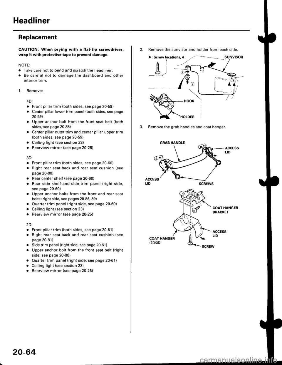
2. Remove the sunvisor and holder from each side.
>: Screw locations,4
-A-,-
3. Remove the grab handles and coat hanger.
scREws
ACCESSLto
COAT HANGERBRACKET
ACCESSLIDCOAT HANGERt2D/3DlSCBEW
1^
Page 1295 of 2189
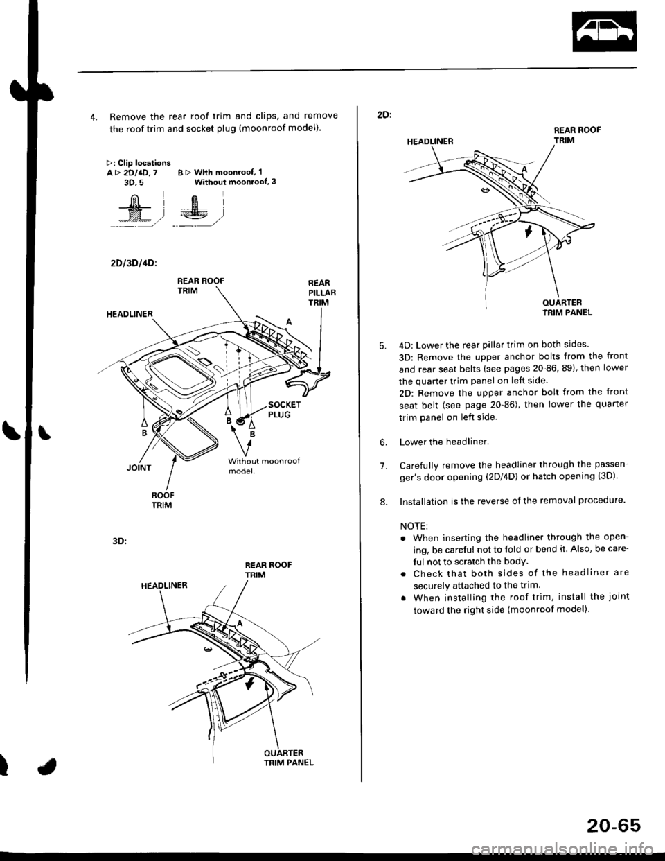
4. Remove the rear roof trim and clips, and remove
the roof trim and socket plug (moonroof model).
>: Clip locationsA> 2DllD,7 B > With moonroof, 'l
3D.5 Without moonroof,3
[il',fEl
t% .l €E .l':: =,/ _._- ,/
2D l3D l4Dl
REAR ROOFTRIM
3D:
t
REAR ROOF
TRIM
2D:
5.
7.
OUARTERIRIM PANEL
4D: Lower the rear pillar trim on both sides
3D: Remove the upper anchor bolts from the front
and rear seat belts (see pages 20-86, 89), then lower
the quarter trim panel on left side.
2D: Remove the upper anchor bolt from the front
seat belt (see page 20-86), then lower the quaner
trim panel on left side.
Lower the headliner.
Carefully remove the headliner through the passen-
ger's door opening (2Dl4D) or hatch opening (3D).
Installation is the reverse of the removal procedure.
NOTE:
. When inserting the headliner through the open-
ing, be careful not to fold or bend it. Also, be care-
ful not to scratch the bodY.
. Check that both sides of the headliner are
securely attached to the trim.
. When installing the roof trim, install the joint
toward the right side (moonroot model)
6.
8.
20-65
Page 1304 of 2189
Front Seat
Removal
CAUTION: When prying with a flat-tip screwdriver, wrapit with protective tape lo prevent damage.
NOTE: Take care not to scratch the seat covers and body.
1. Remove the seat track end cover, then remove thebolts.
SEAT TRACKCOVER
FRONT SEAT
)
SEAT TRACKEND COVER
BOLT8 x'1.25 mft22 N..n 12.2 kgl.m,16 rbf.ft)
8 x 1.25 mm22 N.rn 12,2 kgl.m,16 tbtft)
20-74
2. Lift the driver's front seat, then disconnect the seatbelt switch connector.
SEAT BELTswtTcHCONNECTOR
4.
Remove the headrest.
Carefully remove the front seat through the dooropening.
Installation is the reverse ol the removal procedure.
NOTE: Make sure the connector is connected prop-
erry.
5.
Page 1560 of 2189
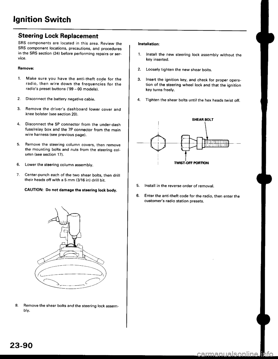
lgnition Switch
Steering Lock Replacement
SRS components are located in this area. Review theSRS component locations. precautions, and procedures
in the SRS section (24) before performing repairs or ser-vtce.
Remove:
LMake sure you have the anti-theft code for theradio, then wire down the frequencies for theradio's preset buttons ('99 - 00 models).
Disconnect the battery negative cable.
Remove the driver's dashboard lower cover andknee bolster (see section 20).
Disconnect the 5P connector from the under-dash
fuse/relay box and the 7P connector from the mainwire harness (see previous page).
Remove the steering column covers, then removethe mounting bolts and nuts from the steering col-umn (see section l7).
Lower the steering column assembly,
Center-punch each of the two shear bolts, then drilltheir heads off with a 5 mm (3/16 in) dritt bit.
CAUTION: Do not damago the steering lock body.
Remove the shear bolts and the steering lock assem,oty.
2.
1.
23-90
Installation:
l. Install the new steering lock assembly without thekey insened.
Loosely tighten the new shear bolts-
Insert the ignition key, and check for proper opera-tion of the steering wheel lock and that the ignitionkey turns freely.
Tighten the shear bolts untilthe hex heads twist off.
TWIST.OFF FORTION
Install in the reverse order of removar.
Enter the anti-theft code for the radio, then enter thecustomer's radio station presets.
sr{€aR SroLT