Page 129 of 2189

Timing Belt
Inspection
1.
2.
3.
Remove the cylinder head cover.
. Refer to page 6 46 when installing.
Remove the upper cover (see page 6 19).
Inspect the timing belt for cracks and oil or coolantsoakrng.
NOTE:
. Replace the belt if oil or coolant soaKeo.. Remove any oil or solvent that gets on the belt.
Rotate pulleyand inspect belt.
After inspecting, retorque the crankshaft pullev bolt{see page 6- 16).
o- I6
Tension Adjustment
CAUTION: lt*ays aa;j"t the timing bett rension withthe engine cold.
NOTE:
. The tensioner is spring loaded to apply tension to thebelt automatically after making the following adjustment.
. Always rotate the crankshaft counterclockwise whenviewed from the pulley side. Rotating it clockwisemay result in improper adjustment of the belt ten-sion.
. lnspect the timing belt before adjusting the belt ten-ston.
1.Remove the cylinder head cover.
. Refer to page 6,46 when installing.
Remove the upper cover (see page 6,'19).
Rotate the crankshaft five or six revolutions to setthe belt.
Set the No. 'l piston at TDC (see page 6-21).
Loosen the adjusting bolt 180'.
2.
3.
4.
5.
\I
ADJUSTING BOLT44 N.m {4.5 kgt m,33 rbf.ft)
7.
8.
Rotate the crankshaft counterclockwise three teethon the camshaft pulley.
Tighten the adjusting bolt.
After inspecting, retorque the crankshaft pulley bolt(see page 6-16).
Page 131 of 2189
Timing Belt
Removal (cont'd)
9. Remove the CKF sensor from the oI pump.
10. Loosen the adjusting bott lgO..to remove tension from theretighten the adjusting bolt.
12 N.m 11.2 kgt.m,8.7 rbf.ftl
Push the tensioner
timing be lt. then
AD.'USNNG BOLT4{ N.m 14.5 kgt m,33 tbtftl
1 1. Remove the timing belt.
6-20
lnstallation
Install the timing belt in the reverse order of removal;Only key points are described here.
l. set rhe timing belt drive pulley so that the No. 1 pis-ton as at top dead center (TDC), Align the groove onthe timing belt drive pulley to the pointer on the oilpump.
TDC MARKPOINTER
I
t
I
TIMING BELTDBIVE PULLEYClean.I
2. Set the camshaft pulley to TDC. Align the TDCmarks on the camshaft pulley to the cylinder headsurface.
Page 138 of 2189

Removal
Engine removal is not required for this procedure
!!!s@ Make sure iacks and salety stands are
f ta"eata"ea propetty and hoist brackets are attached to the
correct positions on the engine.
CAUTION:
. Use tender covels to avoid damaging painted sul-
faces.
o To avoid damage, unplug the wiling connectors
carefully while holding the connector portion to
avoid damage.
. To avoid damaging the cylinder head, wait until the
engine coolant temperature drops below 100"F
{38"C} before loossning the tetaining bolts.
NOTE:
o Mark all wiring and hoses to avoid misconnectlon
Also, be sure that they do not contact other wiring or
hoses, or interfere with other parts.
. Inspect the timing belt before removing the cylinder
h ead.
. Turnthe crankshaft pu lley so that the No. lpistonisat
top dead center (see Page 6-21)
'1. Disconnect the negative terminal from the battery'
Drain the engine coolant (see page'10-7).
a Remove the radiator cap to speed draining.
Remove the intake air duct and air cleaner housing
(see page 5 3).
Remove the mounting bolt and lock bolt. then
remove the power steering (P/S) pump belt and
pump (see page 5'5).
Loosen the idler pulley center nut and adjusting
bolt' then remove the air conditioning (A'lc) com-
pressor belt (see Page 5-6).
Loosen the mounting nut and lock bolt. then
remove the alternator belt (see page 6-19).
Remove the P/S pump bracket (see page 5-12).
3.
4.
2.
6.
1.
8. Remove the throttle cable by loosening the locknut,
then slip the cable end out of the throttle linkage
NOTE:
. Take care not to bend the cable when removing it
Always replace any kinked cable with a new one
. Adjust the throttle cable when installing (see sec-
tion 1 1).
D16Y7 engine:
Dl6Y5, Dl6Y8 engines:
THFOTTLECABLE
(cont'd)
6-27
LOCKNUT
CABLE
Page 139 of 2189
Cylinder Head
Removal (cont'd)
9. Relieve fuel pressure (see section 11),
E@E Do not smoke while working on tho fuelsystem. Ke6p opgn flame or gpark away from lhework area, Drain fuel only into an app.oved containgr.
10. Remove the evaporative emission (EVAP) controlcanister hose, fuel feed hose and breather hose.
D16Y7 engine:
BANJO BOLT33 N.m {3.4 kgt m,25 tbf.ftt
BREATHER HOSE
D15Y5, Dl6YB engines:
BANJO AOLT33 N.m (3.4 kgf.rn,25 tbf.ftt
EVAP CONTROLCANISTER HOSE
6-28
(
1 1. Remove the brake booster vacuum hose. fuel returnhose and vacuum hose (see page S_4).
12. Remove the water bypass hose and positive crank_case ventilation (pCV) hose.
016V7 engine:
PCV HOSE
D16Y5, D16Y8 engines:
\a
I
WATER EYPASS
PCV HOSE
Page 141 of 2189

Cylinder HeadRocker Arms
18.
19.
21.
22.
Removal (cont'd)
Remove the timing belt {see page 6-19).
Remove the camshaft pulley and back cover,
CAMSHAFTPULLEYClean when installing.
6x1.0mm8 x 1.25 mm37 N.m (3.8 kgf.m,21 tbtlrlApply engine oilto thebolt threads.
Remove the exhaust manifold {see pages 9-6 and 9_7).
Remove the intake manifold (see pages 9-2 thru 4).
Remove the cylinder head bolts, then remove thecylinder head.
CAUTION: To pr€vent warpage, unsclew lhe bohsin sequonce 1/3 turn at a time; rgpeat tho sequenceuntil all bolts are loosened.
CYLINDER HEAD BOLTS LOOSENING SEOUENGE:
6-30
Removal
1. Loosen the adjusting screws.
2. Unscrew the camshaft holder bolts, then,removethe rocker arm assembly.
NOTE:
a Unscrew the camshaft holder bolts two turns at at,me, in a crisscross pattern, to prevent damao_ing the valves or rocker arm assembly.. When removing the rocker arm assembly, do notremove the camshaft holder bolts. The bolts willkeep the camshaft holders, the springs and therocker arms on the shaft.
CAMSHAFT HOLDER BOLTS LOOSENINGSEOUENCE:
\(
ADJUSTING SCREWS
Page 147 of 2189

Gamshaft
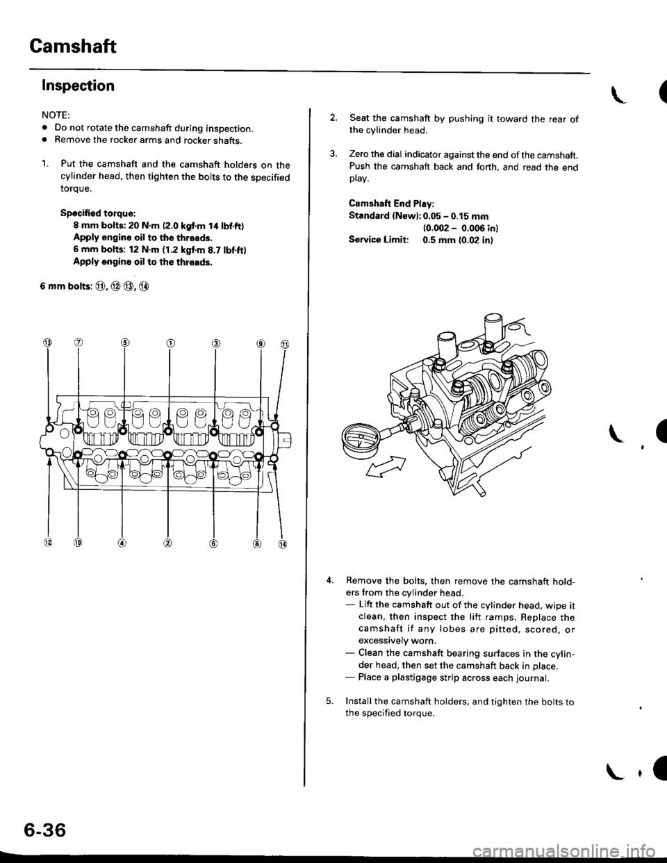
Inspection
NOTE:
. Do not rotate the camshaft during inspection.. Remove the rocker arms and rocker shafts.
1. Put the camshaft and the camshaft holders on thecylinder head. then tighten the bolts to the specified
toroue.
Spocified torqu€:
8 mm bolts; 20 N.m (2.0 kgf.m t4 lbf.ft)Apply engin6 oil to tho throads,
6 mm bohs: t2 N.m (1.2 kgf'm 8.7 tbf.ft)
Apply oogine oil to the thleads.
6 mm bolts: @, @ @, @
6-36
E
\(
2. Seat the camshaft by pushing it toward the rear ofthe cylinder head.
3, Zero the dial indicator against the end ofthe camshaft.Push the camshaft back and fonh, and read the endptav.
Camshaft End Play:
Standard {New):0.05 - 0.15 mm
10.002 - 0.006 inl
Sorvice Limit 0.5 mm (0.02 in,
I
5.
Remove the bolts, then remove the camshaft hold-ers from the cylinder head.- Lift the camshaft out of the cylinder head, wipe itclean, then inspect the liit ramps, Replace thecamshaft if any lobes are pitted. scored, orexcessively worn,- Clean the camshaft bearing surfaces in the cylin-der head, then set the camshaft back in place.- Place a plastigage strip across each Iournal.
Install the camshaft holders, and tighten the bolts tothe soecified toroue.
\,l
Page 155 of 2189

Valves
Camshaft/Rocker Arms and
Camshaft Seal/Pulley
Installation (cont'd)
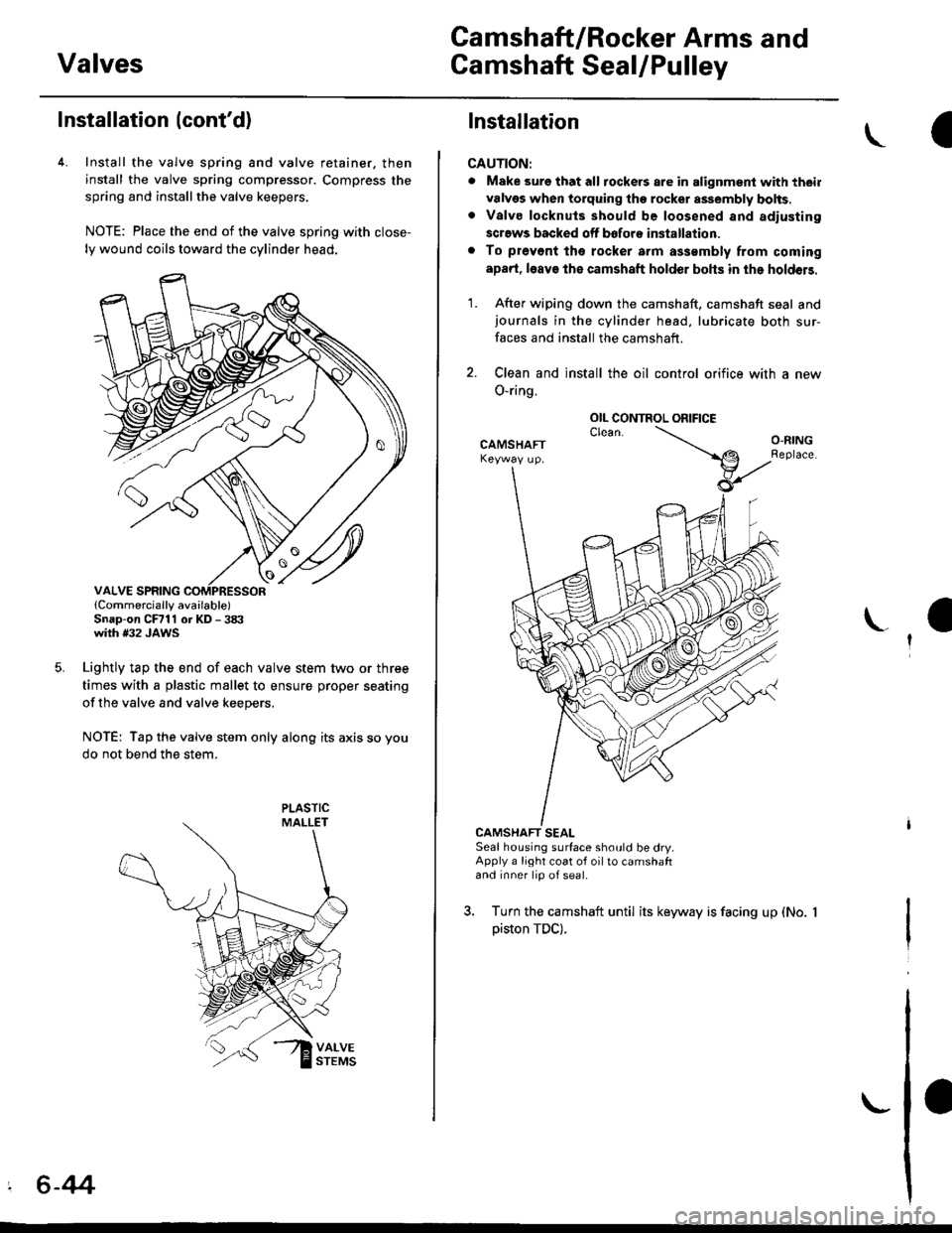
4. Install the valve spring and valve retainer. then
install the valve spring compressor. Compress the
spring and installthe valve keepers.
NOTE: Place the end of the valve spring with close-
ly wound coils toward the cylinder head.
lCornmercially available)Snap-on CFrll or KD - 3tX'with #32 JAWS
Lightly tap the end of each valve stem two or three
times with a plastic mallet to ensure proper seating
of the valve and valve keepers.
NOTE: Tap the valve stem only along its axis so you
do not bend the stem.
' 6-44
Installation
CAUTION:
. Make sure that all tockers are in alignment with their
valvgs when torquing the rocket assembly bolts,. Valve locknuls should be loosened and adiusting
screws backed off bofore installation.
. To prevont tho rocker arm a$smbly from coming
apad, l6av€ the camshaft holder bohs in the holdeB.
1. After wiping down the camshaft, camshaft seal andjournals in the cylinder head, lubricate both sur-
faces and install the camshaft.
2. Clean and install the oil control orifice with a new
O-ring.
CAMSHAFT SEALSeal housing surface should be dry.Apply a light coat of oil to camshaftand inner lip of seal.
3. Turn the camshaft until its keyway is facing up (No.
piston TDC).
OIL CONTROL ORIFICE
Page 156 of 2189

Cylinder Head
4. Apply liquid gasket (Part No. 08718 - 0001 or 08718 -
0003) to the head mating surfaces of the No. 1 and
No.5 camshaft holders.- Apply liquid gasket to the shaded areas
Set the rocker arm assemblY in place and loosely
installthe bolts.- Make sure that the rocker arms are properly posi-
tioned on the valve stems.
Tighten each bolt two turns at a time in the sequence
shown below to ensure that the rockers do not bind
on the valves.
Specitied torquo:
8 mm bolts: 20 N.m (2.0 kgt'm, l/t lbf'ft)
Apply engine oil to the threads.
6 mm bolts: 12 N.m {1.2 kgif'm, 8.7 lbf'ft)
Apply engine oil to the thresds.
6 mm bolts: O, @. @, @
7. Install the back cover. then install the camshaft pul-!
6-45
lnstallation
lnstallthe cylinder head in the reverse order of removal:
NOTE:
. Always use a new head gasket.
. Cylinder head and cylinder block surface must be
clean.
. "UP" mark on the camshaft pulley should be at the top
. Turn the crankshaft so the No. 1 piston is at TDC (see
page 6-20).
. Clean the oil control orifice before installing.
a Do not use the upper cover and lower cover to store
removeo rlems.
Clean the upper cover and lower cover before instal-
taUon.
Cylinder head dowel pins must be aligned.1.
CYUNOER HEAD
PINS
(cont'd)