1996 HONDA CIVIC Shaft seal
[x] Cancel search: Shaft sealPage 625 of 2189

S4C Model ('99 - 00 2-door Si, SiR)
Manual Transmission
Special Tools ............' 13-46
Maintenance
Transmission Oi1 ...................'.......... 13-47
Back-up Light Switch
Repfacement ...""" 13'47
Transmission Assembly
Removal ......'.......... 13-/tB
lnstallation ............. 13-52
lllustrated lndex ................................... 13-54
Transmission Housing
Removal ................. 13-55
Beverse Shift Holder, Reverse ldler Gear
Clearance lnspection ...................".. 13-57
Removal ................. 13-58
Change Holder Assembly
Clearance lnspection .................".... 13-59
Removal ....,,........... 13-61
Disassembly/Reassembly ............... 1 3-62
Mainshaft, Countershaft, Shift Fork
Removal ................. 13-63
Shift Rod
Removal .........."'.... 13-64
Shift Fork Assembly
lndex ................ ...... 13-65
Clearance lnspection .............'......... 13'66
Mainshaft Assembly
lndex ............"" ...... 13-67
Clearance lnspection ....................... 13-68
Disassembly .......... 13-71
fnspection '."'.......', 13'72
Reassembly .......'... 13-73
Countershaft Assembly
fndex ................ "....13-71
Glearance Inspection'......'...........'... 1 3'75
Disassembly .......... 13-76
fnspection .'............13'77
Reassembly "......... 13'78
Synchro Sleeve, Synchro Hub
Inspection .............. 13'8C
Installation ............. 13-80
Synchro Ring, Gear
Inspection .'............ 13-81
Differential
lndex ................ ...... 13-82
Backlash Inspection ..."..........."'...... 1 3-82
Final Driven Gear Replacement ...... 13-83
Bearing Replacement ....."'.......""'.. 13-83
Thrust Shim Adiustment ......""'..... 13-84
Clutch Housing Bearing
Replacement ..'...... 13-86
Mainshaft Thrust Glearance
Adiustment '.........'. 13-88
Transmission
Reassembly ."'....... 13-91
Oil Seals
Replacement ..'...... 13-96
Gearshift Mechanism
Overhaul ................ 13-97
\
Page 635 of 2189

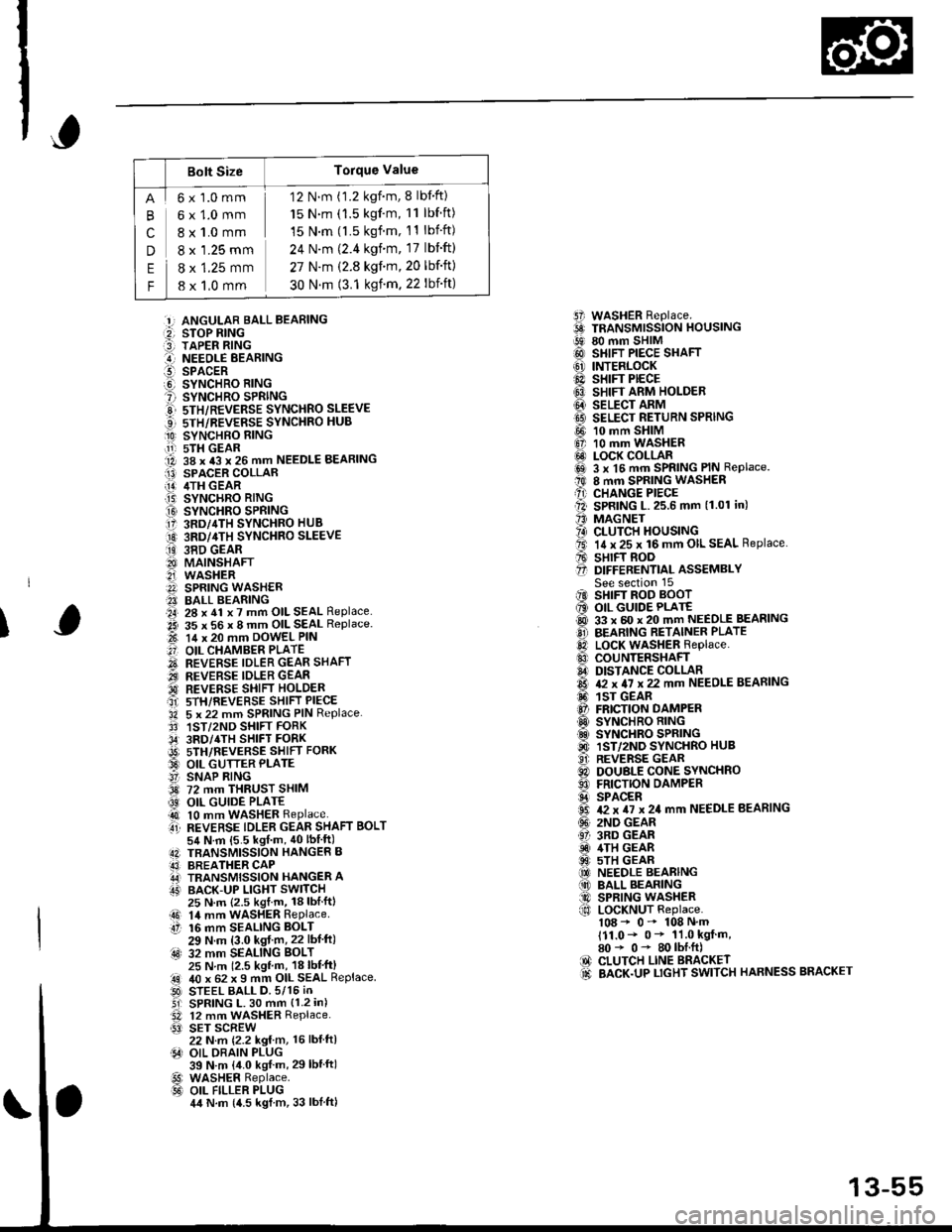
Bolt SizeTorque Value
cn
E
F
6x1.0mm
6x1.0mm
8 x 1.0 mm
8 x '1.25 mm
8 x 1.25 mm
8 x 1,0 mm
12 N.m (1.2 kgnm, 8 lbf'ft)
15 N.m (1.5 kgf'm, 11 lbf ft)
15 N.m (l.5 kgf.m, 11 lbift)
24 N'm (2.4 kgim, 17 lbift)
27 N.m (2.8 kgf.m,20 lbf'ft)
30 N.m (3.1 ksf m. 22 lbift)
5i WASHER Replace.6 TRANSMrssioN HouslNG!9 80 mm SHIM@ SHIFT PIECE SHAFT(6' INTERLOCK@ sHrFr PECE6} SHIFT ARM HOLDER@ seucr nnrvtI9 SELECT RETURN SPRING
@ 10 mm SHIM6, 10 mm WASHER@ LOCK COLLARi6sl 3 x l5 mm SPRING PIN Replace.t0 8 mm SPRING WASHERA) CHANGE PIECEll SPRING L.25.6 mm (1.01 in)'' MAGNET?4) CLUTCH HOUSINGta. 14 x 25 x 16 mm OIL SEAL Replace.A sHrFT BooO D|FFERENT|aL ASSEMBLYSee section 15iIO SHIFT ROD BOOT6 OIL GUIDE PLATE@ 33 x 60 x 20 mm NEEDLE BEASINGO BEARING RETAINER PLATElD LocK WASHER Replace..0 couNTERSHAFIA DISTANCE COLLAR6 & x 4I x 22 mm NEEDLE BEARING6. 1sr GEAR@ FRICTION DAMPERO SYNCHRO RING.d SYNCHRO SPRING@ 1ST/2ND SYNCHRO HUB..9i. REVERSE GEARC) DOUBLE CONE SYNCHROO FRICTION DAMPERS SPACER6 T2 x TI x 24 mm NEEDLE BEARING(!' 2ND GEAR61 3RD GEARiD 4TH GEAR@ 5TH GEAR(O NEEDLE BEARING(10 BALL BEARING@ SPRING WASHERf,o LoCKNUT Replace.108 - 0- 108 N'm111.0- 0* 11.0 kgf m,80* 0- 80lbI.ft)IO CLUTCH LINE BRACKET.d BACK.UP LTGHT SWITCH HARNESS BRACKET
:!, ANGULAR BALL BEABING:2, STOP RING:3] TAPER RING..-I NEEOLE BEARINGl!-- SPACERO SYNCHRO RING? SYNCHRO SPRINGE 5TH/REVERSE SYNCHRO SLEEVE...] sTH/REVERSE SYNCHRO HUB
O SYNCHBO EING.11-r sTH GEAR1A 38 x 43 x 26 mm NEEDLE BEARINGI13) SPACER COLLAR[!] /ITH GEAR.T5) SYNCHRO RING
O SYNCHRO SPRING17 3RD/4TH SYNCHRO HUB
O 3RD/4TH sYNcHRo SLEEVE
ii9 38D GEAR8I MAINSHAFT2i WASHERA SPRING WASH€R?I BALL BEARING.a4, 28 x 41 x 7 mm OIL SEAL Replace..2i 35 x 56 x 8 mm OIL SEAL Replace.t-t 14 x 20 mm DowEL PIN
.'] OIL CHAMBER PLATE
O REVERSE IDLER GEAR SHAFT.iI.., REVERSE IDLER GEAR'd REVERSE SHIFI HOLDERait srH/REVERSE sHIFT PIECE'34 5 x 22 mm SPRING PIN Replace.3' 1ST/2ND SHIFT FORK,34' 3RD/4TH SHIFT FORKi9t) srH/nevense sstrr ronx33 OIL GUTTER PLATE!' SNAP RING3d 72 mm THRUST SHIM
@ OIL GUIDE PLATE4t 10 mm WASHER Replaceti REVERSE TDLER GEAR SHAFT BoLT54 N.m {5.5 kgf m, 40lbIft)4N TBANSMISSION HANGER B43] BREATHER CAPA,J TRANSMISSION HANGER AIT' BACK-UP LIGHT SWITCH
I
25 N.m {2.5 kgl.m, 18lblftl14 mm WASHER RePlaceaO 14 mmtt 16 mm16 mm SEALING BOLT29 N.m (3.0 kgf m,22 lbf ft):4s) 32 mm SEALING BoLT25 N m 12.5 kgl m, 18 lbl'ft)40 x 62 x I mm OIL SEAL ReplaceSTEEL BALL D.5/15 iNSPRING L. 30 mm {1.2 in)12 mm WASHER Replace.SET SCREW22 N.m {2.2 kg{ m, 16 lbl ftlOIL DRAIN PLUG39 N.m {4.0 kgf m, 29lbtftlWASHER Replace.OIL FILLER PLUG4,t N.m {4.5 kgl m, 33 lblftl
.!rl00
@l
13-55
Page 636 of 2189

Transmission Housing
Removal
NOTE: Place the clutch housing on two pieces of wood
thick enough to keep the mainshaft from hitting theworkbench.
'1. Remove the back-up light switch.
2. Remove transmission hanger B.
3. Remove the set screws, the springs, and the steelballs.
BACK.UP UGHTswrTcH
SET SCREW
4. Remove the reverse idler gear shaft bolt.
WASHERReplace.
REVEBSE
13-56
5. Loosen the transmission housing attaching bolts ina crisscross pattern in several steps, then removethem.
TRANSMISSIONHANGER A
R€move the 32 mm sealing bolt.
Expand the snap ring on the countershaft ball bear-ing, and remove it from the groove using a pair ofsnap ring pliers,
32 mm SEALING BOLT
o.
1.
I{
ATTACHING BOLT
SNAP RING
Page 666 of 2189

Clutch Housing Bearing
Replacement
Mainshaft:
L Remove the ball bearing using the special tools asshown.
3/81_ 16 SLIDE HAMMER{commercially available)
ADJUSTAELE BEARINGPULLER, 25 - 40 mm07736 - A01000A
2. Remove the oil seal from the clutch housino.
13-86
CLUTCH HOUSING
BALL BEARING
(
3. Drive the new oil seal into the clutch housing usingthe special tools as shown.
HANOLE07749 - 0010000
ATTACHMENT, 42 x 47 mm07746 - 0010300
4.
OIL S€ALReplace.
Drive the ball bearing into the clutch housing using
the specialtools as shown.
HANDLE07749 - 0010000ATTACHMENT, 52 x 55 mm07746 - 0010il{)0
PILOT, 28 mm07746 - 0041100
Page 669 of 2189

72 mm Thrust Shim
t
Part NumberThickness
23931 - P21 0000.60 mm {0.0236 in}
23932-P21 -0000.63 mm 10.0248 in)
c23933 P21 - 0000.66 mm (0.0260 in)
D23934 - P21 0000.69 mm (0.0272 in)
E2393s-P21-0000.72 mm (0.0283 in)
F23936-P21 -0000.75 mm (0.0295 in)
G23937 -P21-O000.78 mm (0.0307 in)
23938-P21 -0000.81 mm (0.0319 in)
23939-P21 -0000.84 mm (0.0331 in)
J23940-P21 -0000.87 mm (0.0343 in)
K23941 P21 - 0000.90 mm (0.0354 ini
L23942 - P21 0000.93 mm (0.0366 in)
23943-P21 -0000.96 mm 10.0378 in)
N23944 - P21 -0000.99 mm (0.0390 in)
o23945 - P21 0001.02 mm (0.0402 in)
P23946 - P21 0001.05 mm (0.0413 in)
o23947 - P2l 0001.08 mm (0.0425 in)
R23948-P21 -0001.'1 'l mm (0.0437 in)
S23949 - P21 0001.14 mm (0.0449 in)
T23950 - P21 0001.17 mm (0.0461 in)
23951 - P21 -0001.20 mm (0.0472 in)
23952 - P21 -0001.23 mm (0.0484 in)
23953-P21 -0001.26 mm (0.0496 in)
X23954-P21 -0001.29 mm (0.0508 in)
23955 - P21 -0001.32 mm (0.0520 in)
z23956-P21 -0001.35 mm (0.0531 in)
23957-P21 -0001.38 mm 10.0543 in)
AB23958 - P21 -0001.41 mm (0.0555 in)
AC23959 P21 - 0001.44 mm {0.0567 in)
23960 - P21 0001.47 mm (0.0579 in)
AE23961 - P21 -0001.50 mm {0.0591 in)
23962 P21 - 0001.53 mm {0.0602 in)
AG23963-P21 -0001.56 mm (0.0611in)
AH23964-P21 -0001.59 mm {0.0626 in)
23965-P21 -000'1.62 mm {0.0638 in)
23965-P21 - 0001.65 mm (0.0650 in)
AK23967-P21 -0001.68 mm {0.0661 in)
23968 - P21 -0001.71 mm 10.0673 in)
23969 P21 - 0001.74 mm {0.0685 in)
AN23970-P21 -0001.77 mm {0.0697 in)
AO23971 - P21 -0001.80 mm (0.0709 in)
7. lnstallthe thrust shim selected and oil guide plate in
the transmission housing.
72 mm THRUSTOIL GUIDE PLATE
TRANSMISSIONHOUSING
8. Install the spring washer and washer on the ball
beaflng.
NOTE:
. Clean the spring washer, washer and thrust shim
throughly before installation.
. Install the spring washer, washer and thrust
shim properlY.
-WASH€R-<]>-.-'
x -sPRtNG WASHER
-.-sK((9r'
lnstallthe mainshaft in the clutch housing.
Place the transmission housing over the mainshaft
and onto the clutch housing.
Tighten the clutch and transmission housings with
several 8 mm bolts.
NOTE: lt is not necessary to use sealing agent
between the housings.
8 x 1.25 mm
27 N.m (2.8 kgf.m. 20 lbf'ft)
Tap the mainshaft with a plastic hammer.
(cont'd)
9.
10.
'I l.
12.
13-89
Page 671 of 2189

Transmission
ReassemblY
1. Install the new oil seal
2. Set the change Piece.
3. Install the shift rod
4. Install the steel ball' the spring, and the set screw'
5. Install the spring washer and change piece attach-
ing bolt.
6. Install the shift rod boots.
8x1.0mm31 N.m 13.1 kg-m,22lb-ltl
CHANGEPIECE
@:4OIL SEALReplace.SPRINGWASHER
7. Install the oil chamber Plate'
6 x '1.0 mm12 N.m (1.2 kg-m,9lb-ft|
SPRING
, /L.256fim B()(
@ / t't o'ti"l I
{zw"y-6@
q
10.
Set the spring washer and the washer'
lnstall the mainshaft, the countershaft, and the shift
fork assemblies.
NOTE: Align the finger of the interlock with the
groove in the shift fork shaft.
SHIFT FORKS
13-91
Page 675 of 2189

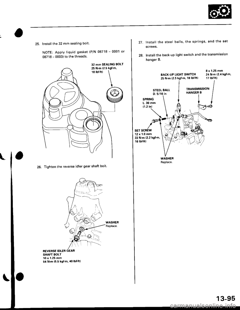
25. Install the 32 mm sealing bolt
NOTE: Apply liquid gasket (P/N 08718 - 0001 or
08718 - 0003) to the threads.
26. Tighten the reverse idler gear shaft bolt'
REVERSE IDLER G€AR
SHAFT BOLT10 x 1.25 mm5a N.rn t5.5 kgl m, {0 lbtftl
32 mm SEALING BOLT
25 N.m {2.5 kgl'm,
lnstall the steel balls, the springs, and the set
screws.
Install the back-up light switch and the transmission
hanger B.
BACK.UP LIGHT SWITCH
25 N.m 12.5 kgt m, 18 lblttl
TRANSMISSIONHANGER B
8x2117
1.25 mmN.m (2.4 kgf m,lbf.ftt
II
I
I
EALL
\\
\
\
SET SCREW'12 x 1.0 mm
22 N.m (2.2 kgf'm,16 tbt.trl
13-95
Page 790 of 2189

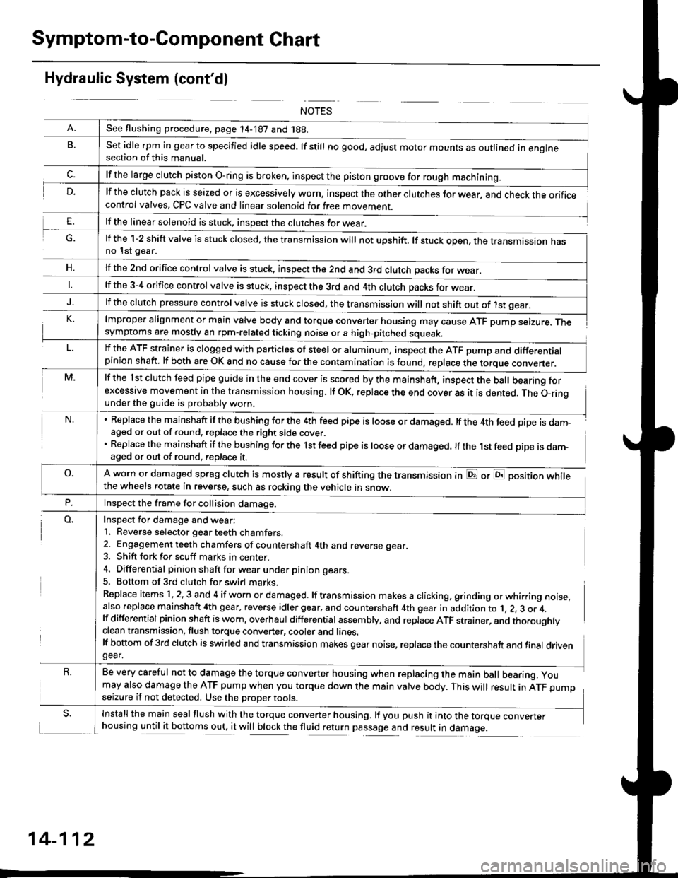
Symptom-to-Component Chart
Hydraulic System (cont'dl
G.
n,
set idle rpm in gear to specified idle speed. lf still no good, adjust motor mounts as outlined in enginesection of this manual.
lf the clutch pack is seized or is excessively worn. inspect the other clutches for wear, and check the orificecontrol valves, CPC valve and linear solenoid for free movement.
lf the linear solenoid is stuck, inspect the clutches for wear.
lmproper alignment or main valve body and torque converter housing may cause ATF pump seizure. Thesymptoms are mostly an rpm-related ticking noise or a high-pitched squeak.
lf the l st clutch feed pipe guide in the end cover is scored by the mainshaft, inspect the ball bearing forexcessive movement in the transmission housing. lf oK, replace the end cover as it is dented. The o-rinounder the guide is probably worn.
Replace the mainshaft if the bushing for the 4th feed pipe is loose or damaged. lf the 4th feed pipe is danFaged or out of round, replace the right side cover.
Replace the mainshaft if the bushing for the 1st feed pipe is loose or damaged. lf the 1st feed pipe is darn-aged or out of round, replace it.
A worn or damaged sprag clutch is mostly a result of shifting the transmission inthe wheels rotate in reverse, such as rocking the vehicle in snow.
or E position while
Inspect for damage and wear:
1. Reverse selector gear teeth chamfers.
2. Engagement teeth chamfers of countershaft 4th and reverse gear.
3. Shift fork for scuff marks in center.
4. Differential pinion shaft for wear u nder pin ion gears.
5. Bottom of 3rd clutch for swirl marks.
Replace items 1,2,3 and 4 if worn or damaged. lf transmission makes a clicking, grinding orwhirring noise,also replace mainshaft 4th gear, reverse idler gear. and countershaft 4th gear in addition to 1, 2, 3 or 4.lf differential pinion shaft is worn, overhaul differential assembly, and replace ATF strainer, and thoroughlyclean transmission, flush torque converter, cooler and lines.lf bottom of 3rd clutch is swirled and transmission makes gear noise, replace the countershaft and final drivengear.
Be very careful not to damage the torque converter housing when replacing the main ball bearing, you
may also damage the ATF pump when you torque down the main valve body. This will result in ATF pumpseizure if not detected. Use the oroper roors.
Install the main seal flush with the torque converter housing. lf you push it into the torque converterhousing until it bottoms out, it will block the fluid return passage and result in damage.
See flushing procedure, page 14-187 and 188.
lf the large clutch piston O-ring is broken, inspect the piston groove for rough machining.
lf the l-2 shift valve is stuck closed, the transmission will not upshift. lf stuck open, the transmission hasno 1st gear.
lf the znd orifice control valve is stuck. inspect the 2nd and 3rd clutch oacks for wear.
lf the 3-4 orifice control valve is stuck, inspect the 3rd and 4th clutch oacks for wear.
lf the clutch pressure control valve is stuck closed, the transmission will not shift out of 1st gear.
lf the ATF strainer is clogged with particles of steel or aluminum, inspect the ATF pump and differentialpinion shaft. lf both are OK and no cause for the contamination is found, replace the torque converter.
Inspect the frame for collision damage.
14-112