Page 1744 of 2189
Circuit Diagram
UNDER-HOOD FUSE/RELAY 8OXIGNITIONSWITCH
WHT/8LI( +WHT
Brake systsm light
passenger's airbag
l----ltlI DUMMY II BESISTOR I
tll
tl
la rl
MEMORY ERASESIGNAT IMES)CONNECTOR I2P)
GRY{GRN)
I
BRN BRN
tl.-l- .-r-\./ \./
ECM/PCM SERVICECHECKCONNECTOR
ILT 8LU
I
t'7
DATA LINKCONNECTOR{DLC) {r6P)
GRY GRY(GRN) IGNN)
V:
G801
Teminalside oi thal€ terminals
24-6
4''
SRS UNIT TERMINALSG40tG402
SBS INDICATOR CIRCUIT{ln the gauge assembly)
PGM_FI
DRIVER'SAIRBAGINFLATOR
10 14 r 13 6 7(VAl 3{VBlSRS UNIT16 17 t5 9 18 8
Page 1763 of 2189
SRS Indicator Light Wire Connections
SRS Indicator Light Power Circuit
DASHBOARD WIRE HARNESS
To UNDER-DASHFUSE/RELAY BOX -
20P CONNECTOR
SRS Indicato. Light Control Circuit
To SRS UNIT
tI
SRS MAIN HARNESS
C41 1, C412 : Terminal sido of mdlo t6rminalsC501, C5O2, C508, C801. C802, C807 : Wi.6 sidc of fomalo t.rminals
MAIN WIBE HARNESS
BLU
C508 -+ To GAUGE ASSEMBLY
c41 1
To GAUGE ASSEMBLY
at
C501 : DASHBOARDWIRE HARNESS 2oP CONNECTORC508 : DASHBOARD wlRE HARNESS 5P CONNECTORC801 : SRS MAIN HARNESS 2P CONNECTORC807 : SRS MAIN HARNESS 18P CONNECTOR
C802 : SRS MAIN HARNESS 3P CONNECTORC412 : MAIN WIRE HARNESS 3P CONNECTORC41 1 : MAIN WIRE HARNESS 24P CONNECTORC502 : DASHBOARD WIRE HARNESS 24P CONNECTOR
GRY
OI
24-25
Page 1764 of 2189
Troubleshooting
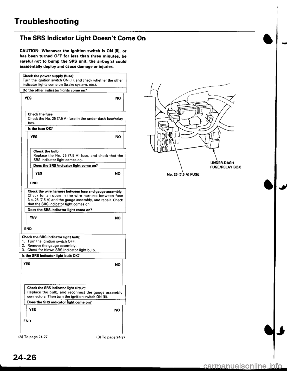
The SRS Indicator Light Doesn't Come On
CAUTION: Whonever ths ignition switch is ON {ll}, or
has been turned OFF tor less than three minutes. be
careful not to bump the SRS unit; the airbagls) could
accidentally deploy .nd caus6 damage or iniuri€s.
Check tho pow€r supply (fuse):
Turn the ignition switch ON (ll), and check whether the otherindicator lights come on (brake system, etc.).
Oo the other indicator liohts como on?
YESNO
Check th6 fuso:Check the No. 25 {7.5 A) fuse in the under-dash tuse/relayb"t
ls th6 tu36 OK?
NOYES
Check the bulb:Replace the No. 25 (7.5 A) fuse, and check that theSRS indicator light comes on.
Doos the SRS indicator liqhl come on7
I YES No
END
Check tho wire harns b€twecn fus6 and gauge aasambly:Check for an open in the wire harness between luseNo. 25 {7.5 A) and the gauge assembly, and repair. Checkthat the SRS indicator light comes on.
Doo. tho SRS indic.tor light como on?
I yEs No
I
END
Check tho SRS indicator light bulb:1. Turn the ignition switch OFF.2. Remove the gauge assembly.3. Check for blown SRS indicator light butb.
ls the SRS indicator light bulb OK?
NOYES
Ch.ck the SnS indicator liglrt circuit:Replace the bulb, and reconnect the gauge assemblyconnectors. Then turn the ignition switch ON {ll}.
Ooes th6 SRS indicato. llght come on?
I YEs No
:ND
lAl To page 24-27
24-26
lB'J fo page 24-27
))
No. 25 (7.5 Al FUSE
Page 1765 of 2189
)
From page 24-26
(A)
From page 24-26
(B)DASHBOARD WIRE HARNESS
5P CONNECTOR
It
MAIN WIRE HARNESS2,rP CONNECTOR
DASHAOARD WIREHARNESS 2irPCONNECTOR
c41 1
(cont'd)
24-27
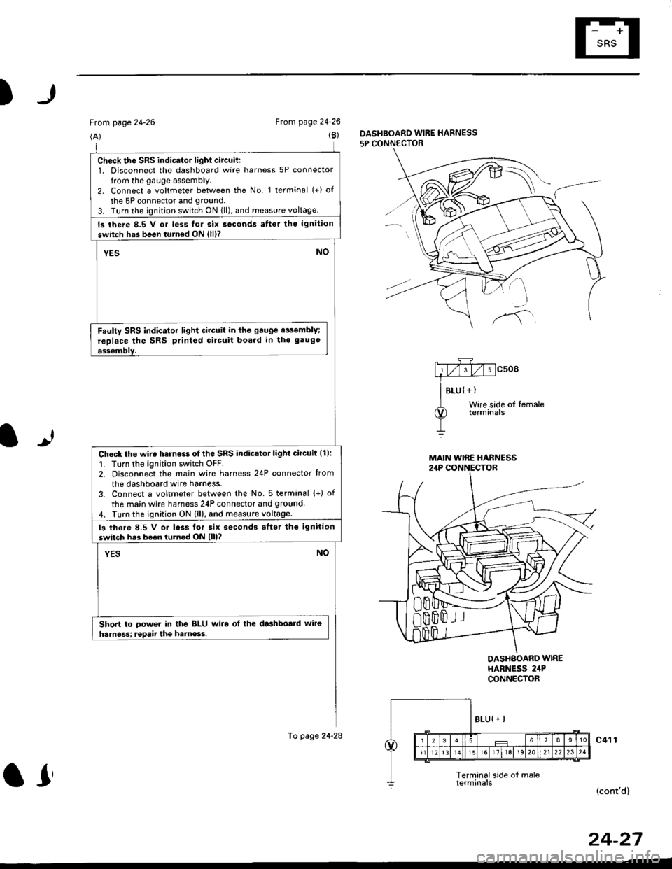
check the sRs indicator light circuit:1. Disconnect the dashboard wire harness 5P connector
from the gauge assembly.2. Connect a voltmeter between the No. 1 terminal (+) of
the 5P connector and ground.
3. T!rn the ignition switch ON 1ll), and meas!re voltage.
ls there 8.5 V or loss lor six seconds atter the ignition
swilch has been turned ON {lll?
YESNO
Faulty SRS indicator light circuit in the gauge e$embly;
replace the SRS printed circuit boa.d in tho gauge
ass€mblY.
Check the wire harness otthe SRS indicator light circuil {1):'1. Turn the ignition switch OFF.2. Disconnect the main wire harness 24P connector from
the dashboard wire harness.
3. Connect a voltmeter between the No. 5 terminal {+) of
the main wire harness 24P connector and 9round4. Turn the ignition ON (ll), and measure voltage.
ls thore 8.5 V or lcss tor tix second3 .Itor the ignition
switch has b6en turned ON lll)?
YESNO
Short to oower in the BLU wire ol the dashboald wiroharness; rgpaii the ham€ss.
To page 24-28
ar
Page 1769 of 2189
)
From page 24'30(B)
To page 24-33
5P CONNECTOF
mcsogA#
I Btu lYEtWire side of fomale
lUUpeA Wtng terminals
OASHBOARD WIRE HARNESS
It
Wire side ol femaletetmtnals
SRS MAIN HARNESSlAP CONNECTOR
(D)
To page 24'33
DASHBOARD WIRE HARNESS5P CONNECTOR
(cont'd)
DASHBOARD WINE HARNESS
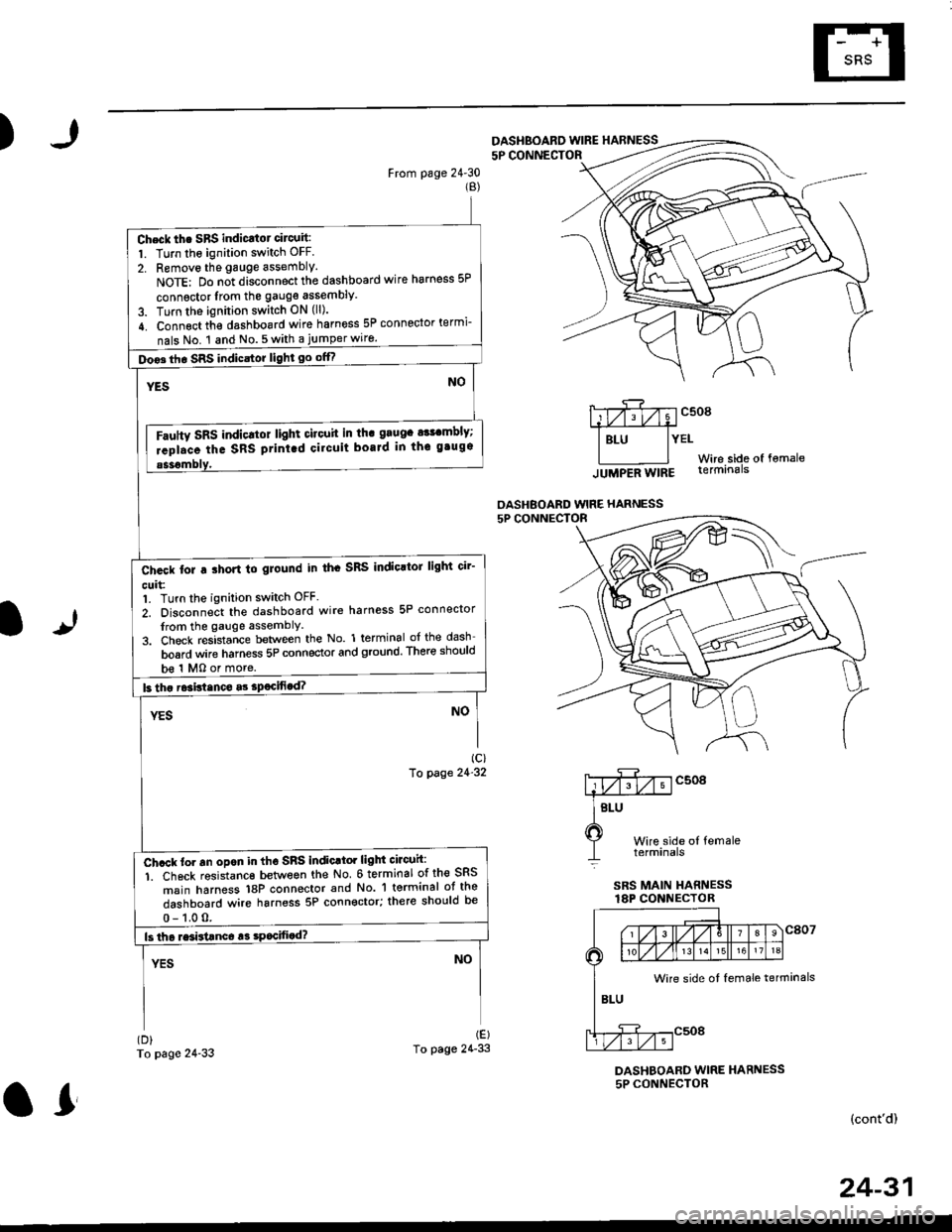
Check th. SBS indicatot circuit:
1. Turn the ignition switch OFF.
2. Removo the gauge assembly.
NoTE: Do n;t disconnect the dashboard wire harness 5P
connsctor lrom the gauge assembly
3. Turn the ignition switch ON (ll).
4. Connect th€ dashboard wire harness 5P connector termi-
nals No. 1 and No.5with a jumperwiro.
Doo3th. SRS indicstor light go offf
Fautty SRS indicltot light citouit in th. grugc a$cmbly;
rcpl.ce the SRS ptint.d cilcuit boaJd in thc gtugs
b€ 1 MO or more.
Ch.ck tor a ihort to glound in th. SRS IndioltoJ light cir'
cuit:1. Turn the ignition switch OFF.
2. Disconnect the dashboard wire harness 5P connector
from the gauge assemblY
3. Check resistance between the No. 1 terminal of the dash
board wire harness 5P connector and ground. There should
Ch.ck to. an opon in tho SnS indic.tor light circuh:
1. Ch6ck resistanc€ between the No 6 terminal of the SRS
msin harness 18P connector and No. 'l terminal ot the
dashboard wire harness 5P connector; there should be
Wire side ot female terminals
24-31
or
Page 1773 of 2189
)
From page 24-34(A)
SRS MAIN HARNESS I8P CONNECTOR
(B)
To page 24-36
1)
Wire sidg of lemale terminals
DASHBOARD WIRE HARNESS
5P CONNECTOR
ic)To page 21'31
DASHBOARD WIRE HARNESS
5P CONNECTOR
c508
t of lemale
(cont'd)
24-35
SRS MAIN HARNESS
Chock iho SRS unit:
Connect the SRS main harness 18P connector terminals No'
6 and No. 3 with a jumper wire and backprobe
Doos tho SRS indicator light go off?
Faulw SRS unit or poot co tact at the SRS ftain htmes!
18P connoctor; chack the connagtot.
ll tha connoctor b OK roplaca lho SRS unit'
oid tu3e No. 23 t10 A) blow?
Chcck for e short to ground in th. SRS indicator lighi cir-
cuh:1. Turn the ignition switch OFF
2. Disconneit the dashboard wire harness 5P connector
from the gauge assembly.
3. Check res-ista;ce between the No l terminai ofth€dash-
board wire harness 5P connector and ground There
should be '1 M0 or more.
Short to glound in th. gaugs aslomblY; .6plac' th' gtug'
JUMPEB WIRE
o!
Page 1774 of 2189
Troubleshooting
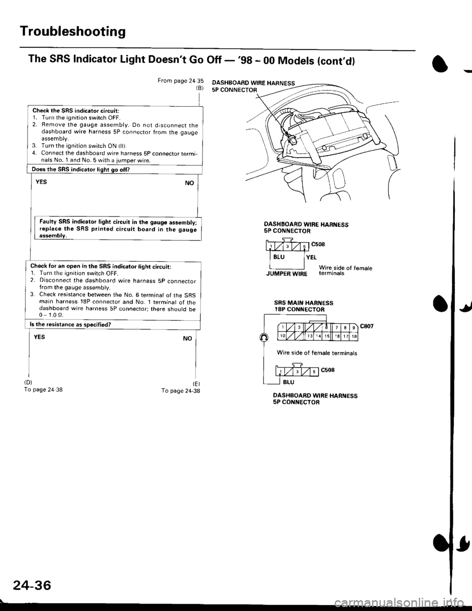
The SRS Indicator Light Doesn't Go Off - '98 - 00 Models (cont,dl
From page 24 351B)
Check the SRS indicetor circuit:1. Turn the ignition switch OFF.2. Bemove the gauge assembly, Do not dlsconnect thedashboard wire harness 5P connector from the gaugeassemoly.3. Turn the ignition switch ON (ll)4. Connect the dashboard wire harness 5P connector termi-nals No. 1 and No. 5 with a jumper wire.
Does the SRS indicator light go om
YESNO
Faulty SRS indicator light circuit in the 9au96 assembly;replace the SRS printed circuit board in the gaugeessembly.
Check for an open in the SRS indicator light circuit:r. rurn rne rqnrton swrtch ut-t-.2. Disconnect the dashboard wire harness 5p connectorfrom the gauge assembly.3. Check resistance between the No. 6 terminal of the SBSmain harness 18P connector and No. I terminal of thedashboard wire harness 5P connector; there should be0 1.0 0.
ls the resistance as soecified?
NOYES
(D)
To page 24 38(E)To page 24-38DASHBOARD WIRE HARNESS5P CONNECTOR
OASHBOARD WIRE HAR'{ESS5P CONNECTOR
llTf;rv;1c508.1#
I Bru lYErWire side of femaleJUMpER WIRE rerminats
SRS MAIN HARi{ESSI8P CONNECTOR
c807
24-36
DASHBOAED WIRE HARNESS
Wire side of female terminals
Page 1835 of 2189
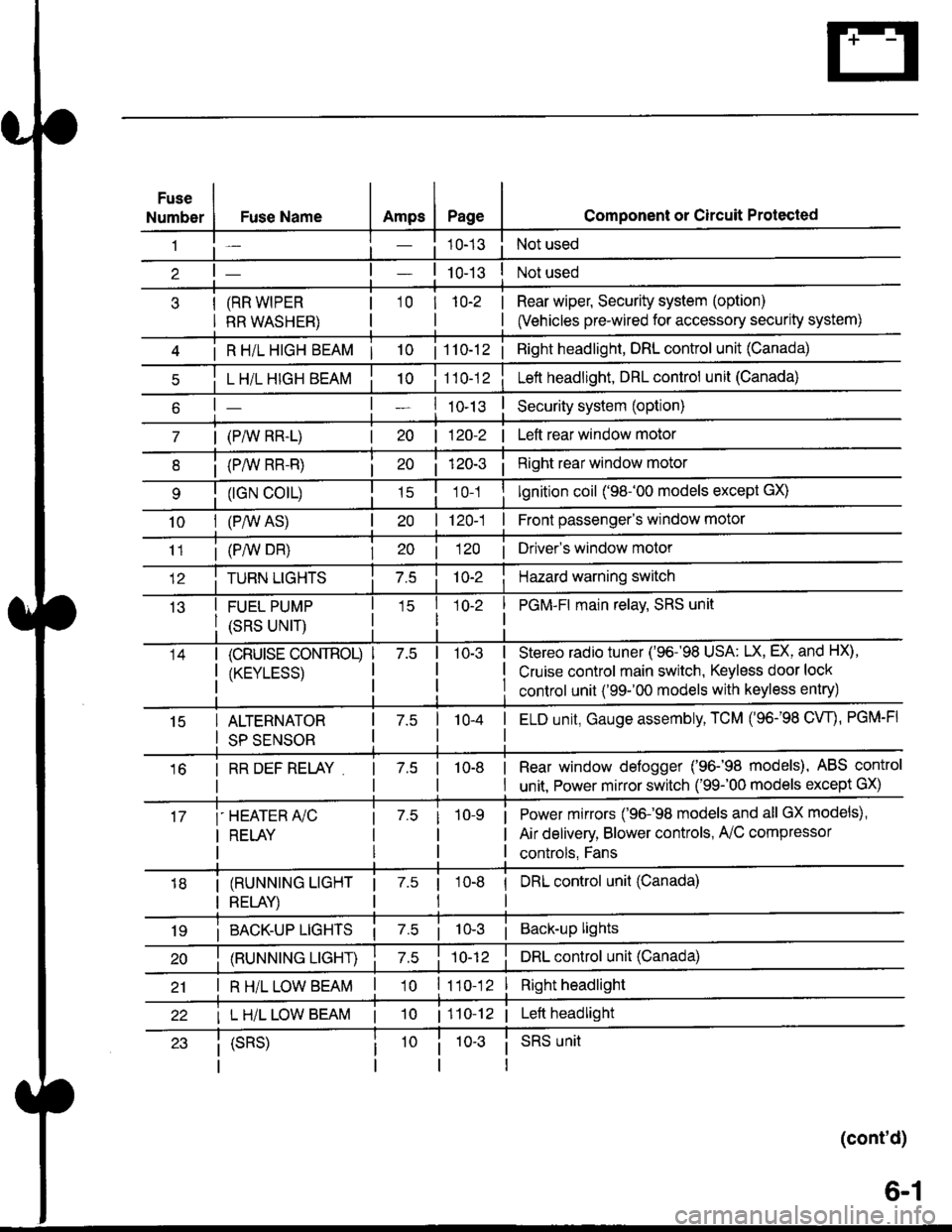
Fuse
NumberAmpsPageFuse Name
(RR WIPER
RR WASHER)
i R HiL HIGH BEAM | 10
L H/L HIGH BEAM
| (PAIV RR-L)
i (P/vv RR-R)
(rGN CO|L)
10I (P,^/V AS)
Component or Circuit Protected
Not used
Not used
Rear wiper, Security system (option)
(Vehicles pre-wired for accessory security system)
'10r 1n-2
I
| 1 10-12i Right headlight, DRL control unit (Canada)
Lett headlight, DRL control unit (Canada)
I ro-rsSecurity system (option)
| 120-2 | Left rear window motor
Right rear window motor
lgnition coil ('98-'00 models except GX)
| 120-1 | Front passenger's window motor
i (PiW DH)| 20 1 12O I Driver's window motor
TURN LIGHTSHazard warning switch
FUEL PUMP
(SRS UNIT)
PGM-FI main relav, SRS unit
(cRUrsE CoNTROL)
/KtrVt trSS\
Stereo radio tuner ('96-'98 USA: LX, EX, and HX),
Cruise control main switch, Keyless door lock
control unit ('99-'00 models with keyless entry)
15ALTERNATOR
SP SENSOR
l-a10-4I ELD unit, Gauge assembly, TCM (96-'98 CW, PGM-FI
16I RR DEF RELAY7.510-8I Rear window defogger ('96-'98 models), ABS control
I unit. Power mirror switch ('99-'00 models except GX)
i-HEATER r/C
I RELAY
Power mirrors ('96-98 models and all GX models),
Air delivery, Blower controls, AilC compressor
controls, Fans
I (RUNNING LIGHT
I RELAY)
1 7.5 1
tl
I DRL control unit (Canada)
i BACK-UP LTGHTSi Back-up lights
(RUNNING LIGHT)DRL control unit (Canada)
I R H/L LOW BEAM'10 l11o-12Right headlight
I L H/L LOW BEAM | 101110-12 | Left headlight
(cont'd)
(SRS)SRS unit
6-1