1996 HONDA CIVIC Kg max
[x] Cancel search: Kg maxPage 865 of 2189
Cooler Flushing
!!!@ To prevent iniury to. face and eyas, always
-ea. safetv glasses ot a face shield when using the
transmission flusher.
NOTE: This procedure should be performed before rein-
stalling the transmission.
1. Check the tool and hoses for wear and cracks before
using. lf wear or cracks are found, replace the hoses
before using.
Using the measuring cup, fill the tank with 2'l ounces
(approximately 2/3 full) of biodegradable flushing
fluid (J35944 - 20). Do not substitute with any other
fluid. Follow the handling procedure on the fluid
contarner.
Secure the flusher filler cap, and pressurize the tank
with compressed air to between 550 - 829 kpa (5 6 -
8.45 kgflcm'�. 80 - 120Psi).
NOTE: The air line should be equipped with a water
trap to ensure a dry air system.
Hang the tool under the vehicle.
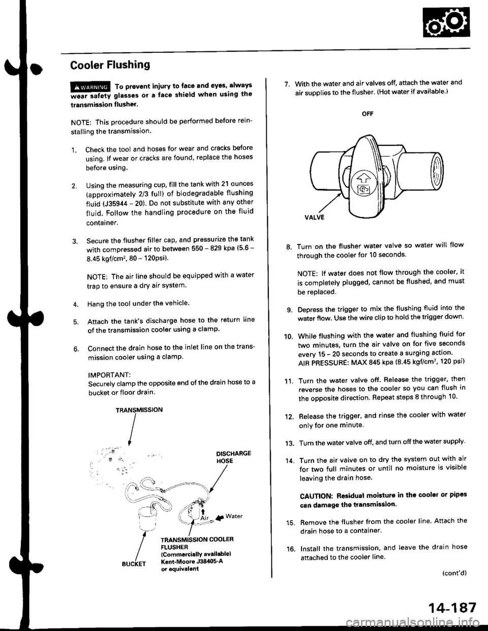
Attach the tank's discharge hose to the return line
of the transmission cooler using a clamp.
Connect the drain hose to the inlet line on the trans-
mission cooler using a clamP
IMPORTANT:
Securely clamp the opposite end oJ the drain hose to a
bucket or floor drain.
TRAMtssroN
TRANSMISSION COOLERFLUSHER{Commcrci.llY avail.blel
Kent-Moore J384O5'Aor equivelent
NS
I
{r Water
7. With the water and air valves off, attach the water and
air suDolies to the flusher' lHot water if available.)
8, Turn on the flusher water valve so water will flow
through the cooler for 10 seconds.
NOTE; lf water does not tlow through the cooler, it
is completely plugged. cannot be flushed, and must
be replaced.
9. Depress the trigger to mix the flushing fluid into the
water flow. Use the wire clip to hold the trigger down'
While flushing with the water and flushing fluid for
two minutes, turn the air valve on for five seconds
everv 15 - 20 seconds to create a surging action'
AIR PRESSURE: MAX 845 kpa {8.45 kgf/cm'�, 120 psi)
Turn the water valve off. Release the trigger, then
reverse the hoses to the cooler so you can flush in
the opposite direction. Repeat steps 8 through 10'
12, Release the trigger, and rinse the cooler with water
onlv for one minute
13. Turn the water valve off, and turn off the water supply
14. Turn the air valve on to dry the system out with air
for two full minutes or until no moisture is visible
leaving the drain hose.
CAUTION: Residual mobturo in tho cooler or pipas
can damage the transmksion'
15. Remove the flusher from the cooler line. Attach the
drain hose to a contalner.
16. Install the transmission, and leave the drain hose
attached to the cooler line
{cont'd)
10.
'11.
14-187
Page 1017 of 2189
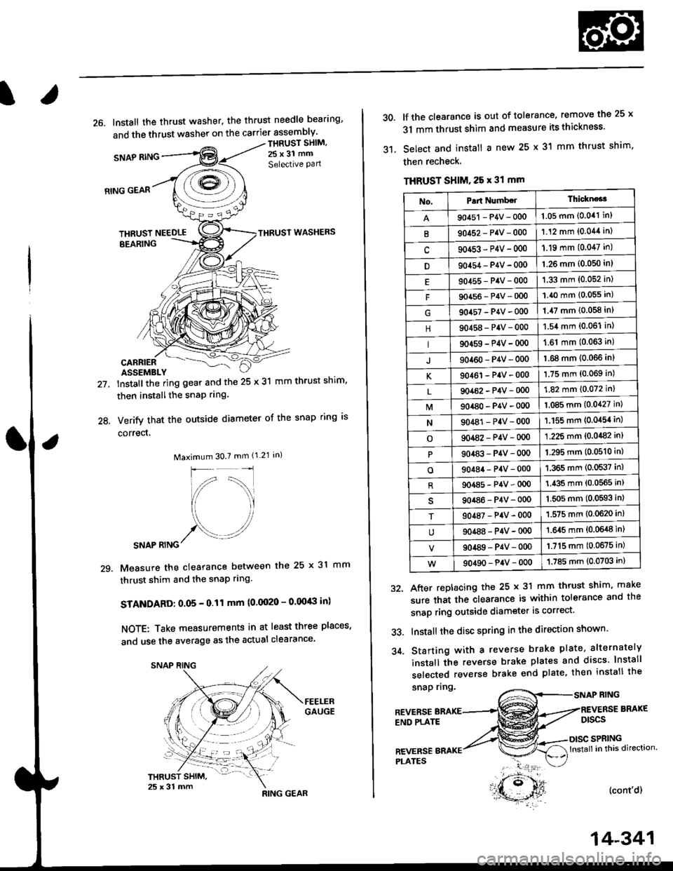
26. Install the thrust washer, the thrust needle bearing'
and the thrust washer on the carrier assembly'
SNAP RING
THRUST SHIM,
25x31 mm
Selective Pan
21.
24.
RING GEAR
THRUST NEEDLETHRUST WASHERS
EEARING
CARRIERASSEMBLY
lnstallthe ring gear and the 25 x 31 mm thrust shim,
then installthe snaP rrng.
Verify that the outside diameter of the snap ring is
correct,
Maximum 30.7 mm (1.21 in)
SNAP RING
Measure the clearance between the 25 x 31 mm
thrust shim and the snaP rlng.
STANDARD: O.O5 - 0.11 mm (0.0020 - 0.00'8 in)
NOTE: Take measurements in at least three places'
and use the average as the actual clearance
29.
,**r#*,".
'- t )
RING GEAR
14-341
30.
31.
lf the clearance is out of tolerance, remove the 25 x
31 mm thrust shim and measure its thickness'
Select and install a new 25 x 31 mm thrust shim.
then recheck.
THRUST SHIM, 25 x 31 mm
snap nng.RING
After replacing the 25 x 31 mm thrust shim, make
sure that the clearance is within tolerance and the
snap ring outside diameter is correct'
Install the disc spring in the direction shown'
Starting with a reverse brake plate, alternately
install the reverse brake plates and discs lnstall
selected reverse brake end plate, then install the
32.
33.
34.
REVERSEEND PLATE
BRAKE
Dtscs
SPRINGlnstall in this direction.
(cont'd)
REVERSEPI-ATES
No.Part Numb.lThickne*3
90451 - P4V - 0001.05 mm (0.041 in)
B90452-P4V-0001.12 mm (0.044 in)
c90453-P4V-000'1.19 mm (0.047 in)
D90454 - P4V - 000'l.26 mm (0.050 in)
90455-P4V-0001.33 mm (0.052 in)
F90456-P4V-0001.40 mm (0.055 in)
904s7-P4V-0001.47 mm (0.058 in)
90458-P4V-0001.54 mm (0.06'l in)
90459-P4V-000'1.61 mm (0.063 in)
J90460-P4V-0001.68 mm (0.066 inl
K90461-P4V-0001.75 mm (0.069 in)
90462-P4V-0001.82 mm (0.072 in)
M904a0-P4V-0001.085 mm (0.0427 in)
N90481-P4V-0001.155 mm (0.0454 in)
o901a2-P4V-0001.225 mm (0.0482 in)
90483-P4V-0001.295 mm (0.0510 in)
o90484-P4V-0001.365 mm (0.0537 in)
R904a5-P4V-0001.435 mm (0.0565 in)
90486-P4V-0001.5O5 mm (0,0593 in)
T90487-P4V-0001.575 mm (0.0620 in)
90488-P4V-00{)1.645 mm {0.0648 in)
90489-P4V-0001.715 mm (0.0675 in)
90490-P4V-0001.785 mm (0.0703 in)
Page 1020 of 2189
Transmission
Reassembly (cont'd)
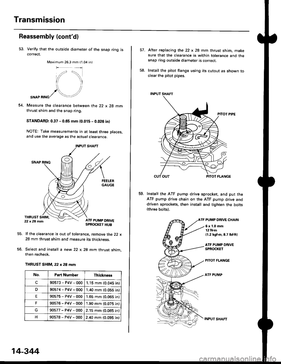
53. Verify that the outside diameter of the snap ring iscorrect.
Maximum 26.3 mm (1.04 in)
54.
SNAP RING
Measure the clearance between the 22 x 28 mmthrust shim and the snap ring.
STANDARD: 0.37 - 0.65 mm (0.015 - 0.026 inl
NOTE: Take measurements in at least three places,
and use the average as the actual clearance.
lf the clearance is out of tolerance, remove the 22 x
28 mm thrust shim and measure its thickness.
Select and install a new 22 x 28 mm thrust shim,then recheck.
THRUST SHIM, 22 x 28 mm
55.
co.
No.Part Numb€rThicknsss
c90573-P4V-0001.15 mm (0.0,{5 in)
D90574-P4V-0001.40 mm {0.055 in)
E90575-P4V-0001.65 mm (0.065 in)
F90576-P4V-0001.90 mm (0.075 in)
90577-P4V-0002.15 mm (0.085 in)
90578-P4V-0002.40 mm (0.095 in)
14-344
INPUT SXAFT
After replacing the 22 x 28 mm thrust shim. makesure that the clearance is within tolerance and thesnap ring outside diameter is correcr.
Install the pitot flange using its cutout as shown toclear the pitot pipes.
Install the ATF pump drive sprocket. and put theATF pump drive chain on the ATF pump drive anddriven sprockets, then install 8nd tighten the bolts(three bolts).
TF PUMP DRIVE CHAIN
58.
59.
6x1.0mm12 N.m
11.2 kg{.m,8.7 lbf.ftl
ATF PUMP ORIVESPROCKET
PITOT FLANGE
ATF PUMP
Page 1028 of 2189
Transmission
Gooler Flushing
@ To prevent iniury to face and eyes, alwayswear safety glasses or a tace shield when using thetransmission flusher.
NOTE: This procedure should be performed before rein-stalling the transmission.
'1. Check the tools and hoses for wear and cracks before
using. lf wear or cracks are found, reDlace the hoses
before using.
4.
Using the measuring cup. fill the tank with 2,1 ounces(approximately 2/3 full) of biodegradable flushingfluid (J35944 - 20). Do not substitute with any otherfluid. Follow the handling procedure on the fluidcontatner.
Secure the flusher filler cap, and pressurize the tankwith compressed air to between 5S0 - 829 kpa (5.6 -
8.45 kgf/cm'�, 80 - 120 psi).
NOTE: The air line should be equipped with a watertrap to ensure a dry air system,
Hang the tool under the vehicle.
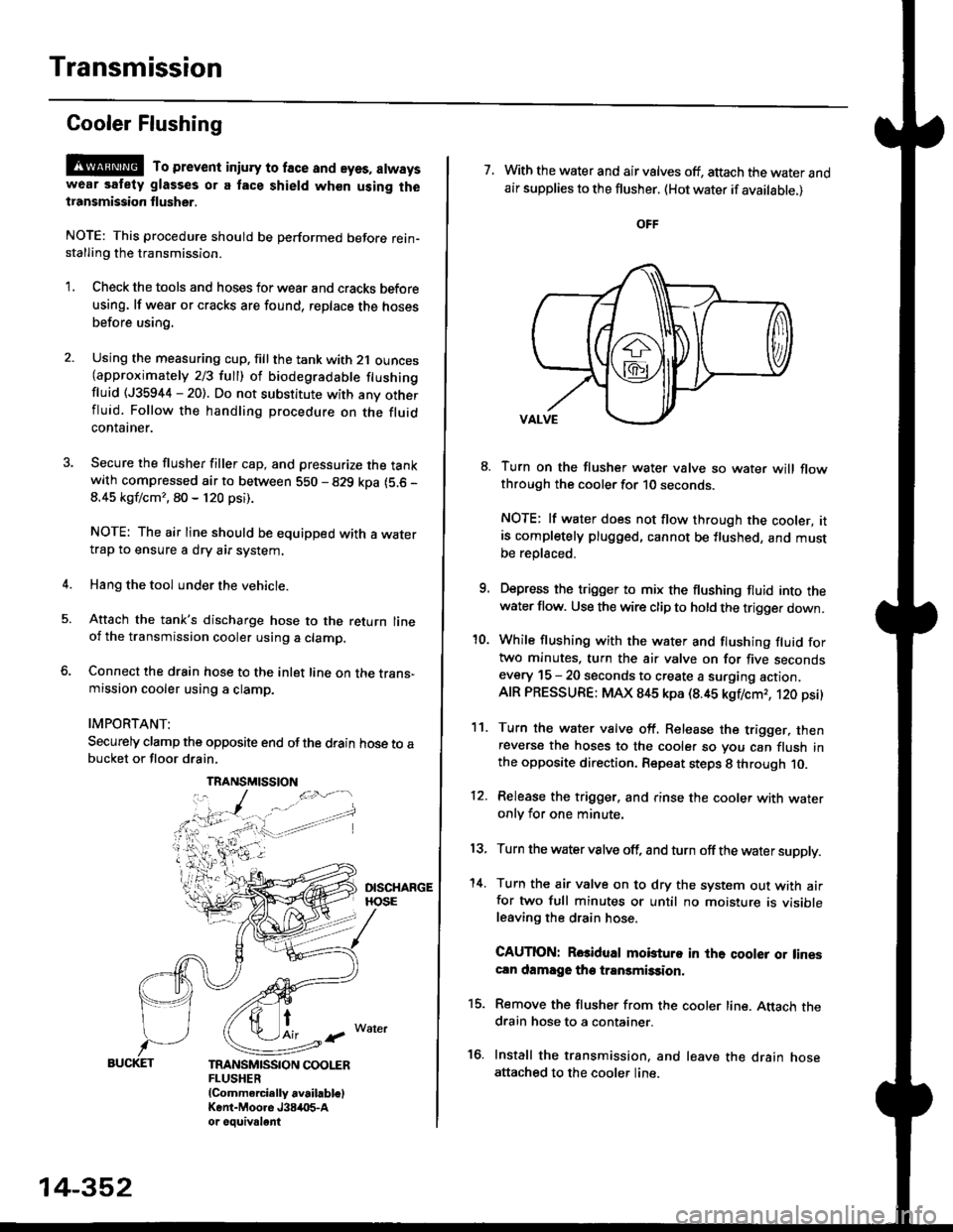
Attach the tank's discharge hose to the return lineoi the transmission cooler using a clamp.
Connect the drain hose to the inlet line on the trans-mission cooler using a clamp.
IMPORTANT:
Securely clamp the opposite end ofthe drain hose to abucket or floor drain,
t
TRANSMISSION COOLERFLUSHER{Commercially available)Kent-Moore J384O5-Aor oouivalent
TRANSMISSION
14-352
7. With the water and air valves off, attach the water andair supplies to the flusher. (Hot water if available.)
8. Turn on the flusher water valve so water will flowthrough the cooler for 10 seconds.
NOTE: lf water does not flow through the cooler, itis completely plugged, cannot be flushed, and mustbe replsced.
9. Depress the trigger to mix the flushing fluid into thewater flow. Use the wire clip to hold the trigger down.
'10. While flushing with the water and flushing fluid fortwo minutes. turn the air valve on for five secondsevery 15 - 20 seconds to create a surging action.AIR PRESSURE: MAX 845 kpa (8.45 kgflcmr, 120 psi)
11. Turn the water valve off. Release the trigger, thenreverse the hoses to the cooler so you can flush inthe opposite direction. Repeat steps 8 through 10.
12. Release the trigger. and rinse the cooler with wateronly for one minute.
13, Turn the water valve off, and turn off the water supply.
'14. Turn the air valve on to dry the system out with airfor two full minutes or until no moisture is visibleleaving the drain hose.
CAUTION: Rosidual mobturo in the qooler or linescln damage the transmission,
15. Remove the flusher from the cooler line. Attach thedrain hose to a container.
16. Install the transmission. and leave the drain hoseattached to the cooler line.
Page 1049 of 2189
Driveshafts
Reassembly lcont'd)
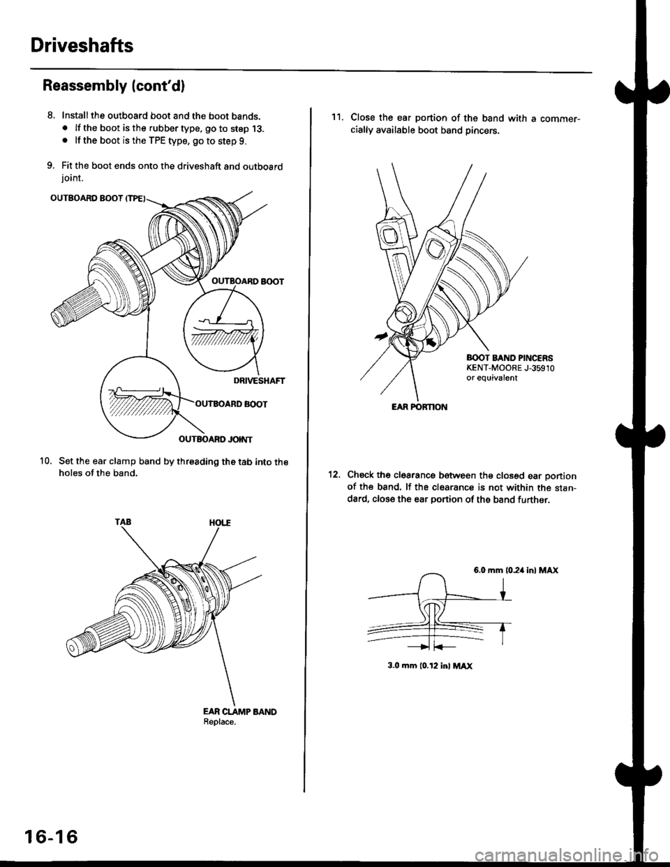
Installthe outboard boot and the boot bands.. lf the boot is the rubber type. go to step 13.. lf the boot is the TPE type, go to step 9.
Fit the boot ends onto the driveshaft and outboard
ioint.
10, Set the ear clamp band by threading the tab into theholes of the band.
EAR CLAMP BANDReolace.
8.
16-16
11. Close the ear portion of the band with a commer-cially available boot band Dincerc.
BOOT BAND PINCERSKENT-MOORE J,35910or eouivalent
Chsck the clearanca between the closed ear oonionof the band. lf the clesrance is not within the stan-
dard, close the ear portion of ths band further.
6.0 mm (0.24 in) MAX
3.0 mm 10.t2 inl MAX
EAR FOFNON
Page 1060 of 2189
Inspection and Adjustment
Steering Operation
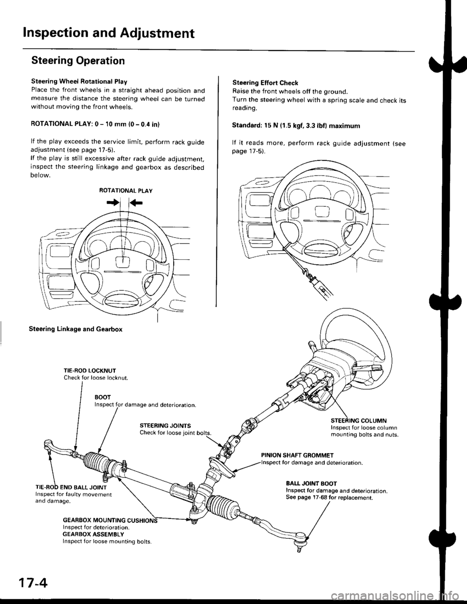
Steering Wheel Rotational Play
Place the front wheels in a straight ahead position andmeasure the distance the steering wheel can be turnedwithout moving the front wheels.
ROTATIONAL PLAY: 0 - 10 mm (0 - 0.4 in)
lf the play exceeds the service limit, perform rack guide
adjustment (see page lT-5).
lf the play is still excessive after rack guide adjustment,inspect the steering linkage and gearbox as descrjbed
Detow.
Steering Linkage and Gearbox
TIE.ROO LOCKNUTCheck for loose locknut.
BOOTInspect for damage and deterioration.
STEERING JOINTSCheck for loose joint
END BALL JOINTInspect for faulty movementano oamage.
GEABBOX MOUNTINGInspect f or deterioration.GEABBOX ASSEMBLY
Ste€ring Effort Check
Raise the front wheels off the ground.
Turn the steering wheel with a spring scale and check itsreaorng,
Standard: 15 N (1.5 kgf, 3.3 lbll maximum
lf it reads more. perform rack guide adjustment (see
page 17-5).
COLUMNInspect for loose columnmounting bolts and nuts.
PINION SHAFT GROMMETfor damage and deterioration.
BALL JOINT BOOTInspect for damage and deterioration.See pago 17-68 tor replacement.
ao-\---------U
17-4
Inspect for loose mounting bolts.
Page 1061 of 2189
Steering Gearbox
l.r
Rack Guide Adjustment
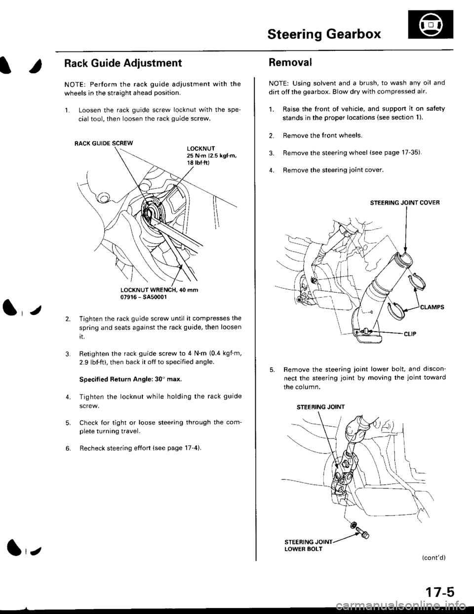
NOTE: Perform the rack guide adjustment with the
wheels in the straight ahead position.
1. Loosen the rack guide screw locknut with the spe-
cial tool, then loosen the rack guide screw.
LOCKNUT WRENCH, 40 mm07916 - SA5000r
Tighten the rack guide screw until it compresses the
spring and seats against the rack guide, then loosen
rt.
Retighten the rack guide screw to 4 N'm (0.4 kgf m,
2.9 lbf.ft), then back it off to specified angle.
Specilied Return Angle: 30' max.
Tighten the locknut while holding the rack guide
Check for tight or loose steering through the com-
plete turning travel.
Recheck steering effort (see page 17-4).
4.
RACK GUIDE SCREW
l,z
Removal
NOTE: Using solvent and a brush, to wash any oil and
dirt off the gearbox. Blow dry with compressed air.
1. Raise the front of vehicle, and support it on satety
stands in the proper locations (see section I ).
2. Remove the front wheels.
3. Remove the steering wheel (see page 17-35).
4. Remove the steering loint cover
Remove the steering joint lower bolt, and discon-
nect the steering joint by moving the joint toward
the column.
(cont'd)
17-5
STEERING JOINT COVER
LOWER BOLT
STEERING JOINT
Page 1076 of 2189
System Description
Steering Gearbox
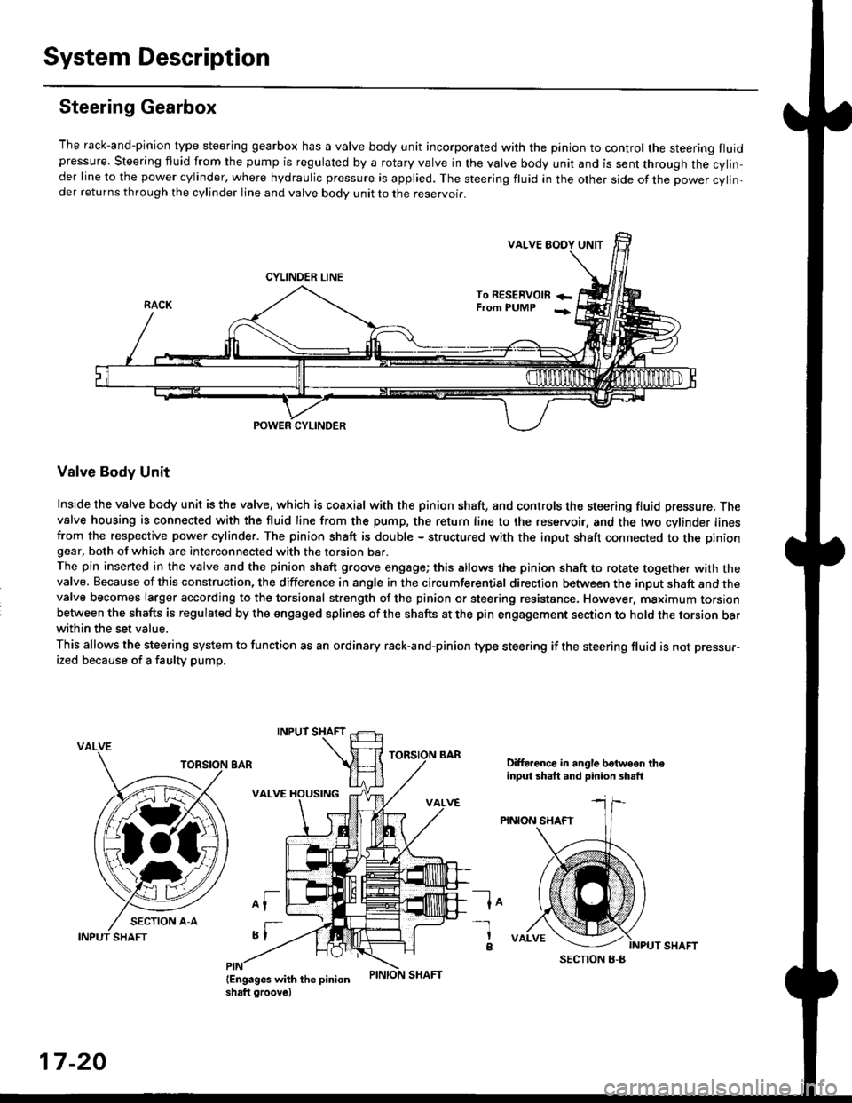
The rack-and-pinion type steering gearbox has a valve body unit incorporated with the pinion to control the steering fluidpressure. Steering fluid from the pump is regulated by a rotary valve in the valve body unit and is sent through the cylin,der line to the power cylinder, where hydraulic pressure is applied. The steering fluid in the other side of the power cylin,der returns through the cylinder line and valve body unit to the reservoii.
VALVE EODY UNIT
CYLINDER LINE
To RESERVOm +-From PUMP -;
POWER CYLINDER
Valve Body Unit
Inside the valve body unit is the valve, which is coaxial with the pinion shaft, and controls the steering fluid pressure. Thevalve housing is connected with the fluid line from the pump, the return line to the reservoir, and the two cylinder linesfrom the respective power cylinder. The pinion shaft is double - structured with the input shaft connected to the piniongear, both of which are interconnected with the torsion bar.
The pin inserted in the valve and the pinion shaft groove engage; this allows the pinion shaft to rotate together with thevalve. Because of this construction, the difference in angle in the circumferential direction between the input shaft and thevalve becomes larger according to the torsional strength of the pinion or steering resistance. However, maximum torsionbetween the shafts is regulated by the engaged splines of the shafts at the pin engagement section to hold the torsion barwithin the set value,
This allows the steering system to function as an ordinary rack-and-pinion type steering if the steering fluid is not pressur-
ized because of a faulty pump,
VALVE
Difforence in angle botwoon theinput shaft and pinion shsft
PINION SHAFT
lo
INPUT SHAFT
-l
a
17-20
INPUT SHAFT