Page 1916 of 2189
Vehicle Speed Sensor (VSS)
il';;---lI ALTENNATOA I
I I""::,",,", !
Lr_f1l_i
".*,1,[ 9#":1"
\.(
UNDER-DASHFUSE/RELAYBOXPHO|O 5a
I v"ni"t"
l:g9qd
iineilt i
12
CRUISECONTROLUNIT
vtEw 43
I v"ni"p I
l:p"gd I
I'T$, I
TRANS.MtsstoNCONTROLMODULE
FCM)
vtEw 69
! !iio',6T""f
EtuwHr|
!y:ll*!Bb'^i1?'J.'
! so""oo- ! iffiilr*J l;6';irtE!;i#:*! il il iiTs'l, iipEr',r"L---J I I L - J D.^..1*B11 Y [ [ (-C18) Y vtLNTo
l;i"i;'! [ [ l'ffi, liib-r,ro,ecu1
See Power Distribution,page 10-5.(
lgnitjonVohielespeeoouptn
Ground
Y' """-' Oerminats 1.t-13)
vlEw 52
VEHICLESPEEDSENSOR(VSS)PHATA 35
= '96- 98: Allmodels except D1685'99 00: D 1 6Y5 w th Lr/T= '96-'98: All models'99-'00: D16Y5 with M/I D1685
.i,
a33
Page 1917 of 2189
- How the Gircuit Works
With the ignition switch in ON (ll) or START (lll),
battery voltage is supplied through fuse 15 and
the BLI(WHT and BLK/YEL wire to the vehicle
speed sensor (VSS). The sensor is grounded by
the BLK wire to G1 01 . The speedometer and
other control units in the circuit supply about 5
volts to the BLU/WHT wire. The vehicle soeed
sensor (VSS) intermittently grounds the
BLUMHT wire which generates a pulsed signal
in it. The number of pulses per minute
increases/decreasos with the soeed of the car.
Reter to th€ Service Manual (Section 23, Electrical)
tor specific tosts or troubleshooting procedures.
33-1
Page 1921 of 2189
i - '99100 016Y7/D16Y8 with A"/T -
Cruiseconrolsgnal
i8s) i
iil
POWERTRAINCONTROLMODULE(PcM)
* = '96-'98: All models'99100: D16Y5 with M/T, 01685
-----i-----.lcRU|sE
| ; Cruise control ' I CONTROL
signaloutput ' |oNirI PHATO 55
I oisengage input vehicle speed input ' vtEw 13
.--------;---- ---J
See Vehicle
Sensor rySS)
See GfoundDigtribution,page 14-5.
I
J
"{
,--r-s=-.
CLUTCHswtTcHOpen withclutch pedaloepresseo.
A/T GEARPOSITIONswtTcH
L- ----
ALU,ryVHT
3x
ct30Cferminals11.13)PHATO E3vlEw 52See GrolndDlslribution,page 14-6.
IY
ll
L__l#: G401
lI:::1" I
I output I
VEHICLESPEEDSENSOR(vss)
O-a
34-3
Page 1922 of 2189

Gruise Control (cont'd)
- How the Circuit Works
The cruise control system uses mechanical and
electrical devices to maintain the car's sDeed at a
setting selected by the driver.
System Description
The cruise control unit receives command signals
from the crurse control main switch and the cruise
control SeVResume switch. With the ignition switch
in ON (ll) or START (lll), voltage is provided to the
cruise control main switch through fuse 14. When
you push the switch to ON, power is provided to the
cruise control unit and the brake switch.
The cruise control unit receives information about
operating conditions from the brake switch, the
vehicle speed sensor (VSS), and the clutch switch
(manual transmission) or the A,/T gear position
switch (automatic transmission). The cruise control
unit then sends signals to the cruise control actuator
which regulates the throttle position to maintain the
selected speed. The conlrol unit compares the
actual speed of the car to the selected speed. The
control unit then uses the result of that comoarison
to open or close the throttle.
The brake switch releases the system's control of
the throttle at the instant you press on the brake
pedal. The switch sends a signal to the control unit
by removing power from the normally closed brake
input (GRY wire), and providing power at the
normally open brake input (GRN/vVHT wire). The
control unit responds by allowing the throttle to
close. The clutch switch or the A,/T gear position
switch sends a "disengage" signal to the control unit
that also allows the throttle to close.
The cruise control system will set and automatically
maintain any speed above 25 mph (40 km/h). To set
it, make sure the main switch is on and the switch
indicator is on. Then, after reaching the desired
speed, press the SET switch. This sends a "set"
signal to the cruise control unit which, in turn,
controls the cruise control actuator to maintain the
set speed.
When you push the SET switch and the cruise
control system is on, the "cruise control" ON
indicator lights up.
34-4
(
You can cancel the cruise control system by
turning the main switch off . This removes power to
the control unit and erases the set speed from
memory. lf the system is disengaged temporarily
by the brake switch, or clutch switch, and the car's
speed is still above 25 mph, press the resume
switch: the car will automatically return to the
previously set speed.
For gradual acceleration without pressing the
accelerator pedal, push the RESUME switch and
hold it there. This will send an "acceleration" signal
to the control unit. When you release the switch, the
system will be reprogrammed for the new speed. To
slow the car down. oush the SET switch in and hold
it there. This sends a "deceleration" signal to the
control unit, causing the car to coast. When the
desired speed is reached, release the SET switch.
This reprograms the system tor the new speed.
Refer to the Service Manual (Section 23, Electrical)
tor specific tests or troubleshooting procedures.
(
a
Page 1923 of 2189

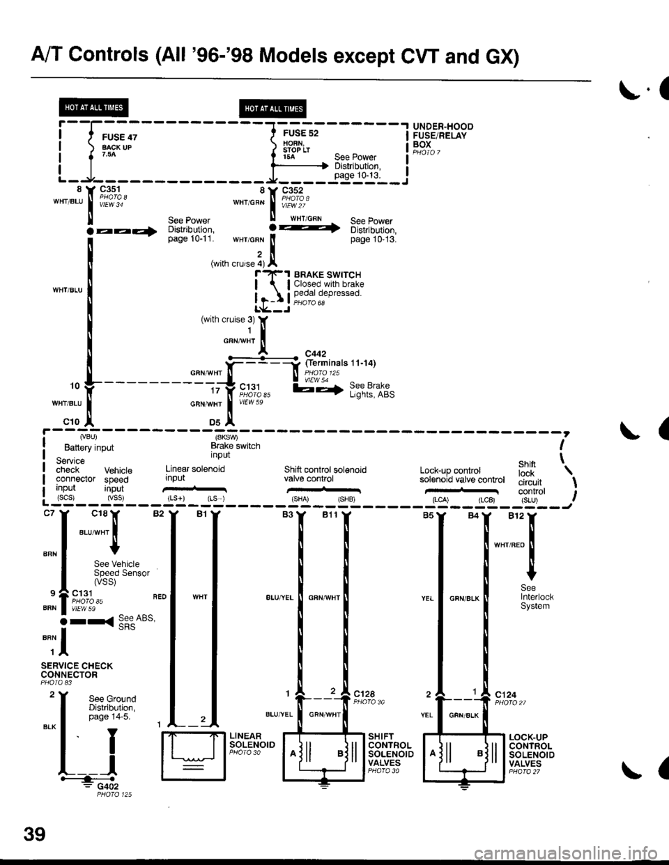
A/T Controls (All '96-'98 Models except CW and GX)
r.(
r5A see power I
--li$"i':,--iL-.At----- __*____..,,53-j"i__8 Y 93^s_1- 8Y C352'"'".u
I iii'i"' ""'o"* | i#?1o.'
ll see power ll wrr cnn See Power
la--- oisirioution, ! -t 6iri,iortion,
[--*
t"*tr*t1,'.':,:;i. wHr GFN lt page 10-13.
,i(with crurse 4) Al"'rl(-1 BRAKE swrrcH
| lClosed.with brake
Ir-I Il,?,|fll,"P'"""oL*--J
c18lr 82
"ar-"t I
I
See VehicleSpeed Sensor(vss)
ct31PHO|O 35vtEw 59
r< See ABs'
UNDER"HOODFUSE/RELAYBOXI
I
I
BFN
9
BFN
o
""il
SERVICE CHECKCONNECTOR
See GroundDistribution,page 14-5.
I
YEL
c124
L__lH:""".: G402
SHIFTCONTROLSOLENOIDVALVES
LOCK-UPCONTROLSOLENOIDVALVES
,. L ---- - - --.#ku" :::::'o f
---------tty"c;11,, l;-,f l;?t?:if,-:;tr *";.!, *"
c10 ,| Ds^'
I Lvou, (SKSV,
! Battery input Brake lwitch I
service nPUt ehin t;;;;i- Vehrcte Linear sotenoid Shift controt sol€noid Lock-up conkol iJ'[
'\
connector speed input valve conhol solenoid vatve controt tliiJ"it \uo trut tconrrol t: (scs) (vss) {Ls}) rLs ) {sHA' {SHB, (LCA) (LCB) {S-U) .--:-'--J
ct28
39
GFN/ALK
(
Page 1924 of 2189
@@
i t FusE 13
LJ::-i1":--.i
---1 UNDET
| | ryql* !5ts?'n| ) iL"' li'r:,o,
rT ILJ---------J
--1 UNDER.DASH T ---1 UNDER-HOOD
i l$5ffif{61 !F'[]:':'* itte*- l"l;?::*'
L-g----- ---Y---J3 r-----
---------;r
".* I veuar-r< |, t_____ _1ft9#;,,
"* | ;-{ 8pfitli*| ".'"'* |
n"""
l----l .rr^ Page 14 1
-Fliirn"r"a-rq) 1' i====f:a&l?f''inarsra-rzr
"*l w;?"* ! .._ _ .l .- " .l *.*- I #it;;;--
-
lara-i-�-�'' i I @DP':,-rt
r=- 9,lo,l' o.,., I *ol- --t PowER-(rGPr) rrcP2lI TRAIN
Countersl€lt so€€d
sbneor
lJt
"":I ""1I BRNJELX
"r, | "'0 I
!-
-CIG; - - - - - - - -*-r- - 1 PowERTRAIN
t sensor t"r'ii. | .c.gl,rfgL
I gourd ground I F;-r,r;*L------- J iuoro ea
Mainshaftspoedsensorinpd
Power input
#lvrrwzo
CONTROLMODULE(PCM)PHOTO 86
(NM) (PG1) {P62) {LG0 (LG2)
":[
;{ ]1
::l -X ;;
rfl lfi* *T'r+*
| | |
:T'-jru,,L#, il
3.[iF;" H ;,$5*" I
n:'r:T'"'uo
l #lt':.See GrourdDisttlbution,page 14.
(cont'd)
BRN/BLKBFN/BLK
39-1
Page 1927 of 2189

L-L----:-------J----L"egyJ*"" !tr;:tl1tfl i*"?]( 9;%, 8Y ge-q? LJ-------,;li, ! *rr1-....^^ s€s tuwer *"to"n ! if?ror ,r"r,o"n - sse power 14 y g4^1_q --
I
I
o*"clt](/manual-img/13/6068/w960_6068-1926.png)
AIT Controls ('96-'98 CVT)
L-L----:-------J----L"egyJ*"'"' !tr;:tl1tfl' i*"?]( 9;%, 8Y ge-q? LJ-------,;li, ! *rr1-....^^ s€s tuwer *"to"n ! if?'ror' ,r"r,o"n - sse power 14 y g4^1_q --
I
I
o*"'clt. *'"1,!. tad;1di3]
t
-""
I HFr:{tv][[:F I
*l """-tl-.
"*,
*-,-*l
t;
^,.[
"-;;[ 1#E;;;::";mi
.aa4 ;;r;;", : ----+ u,"i.,-uon, i;;;;r.
i {vBt) (sToP sw) (Gl) flc1l
! Battery input Brake switch lgnilion tgniuon| -^-,^^ ' inpui fipr,- i;;i;iSeMce input i;put iiput t
| #;if vehicle Engin€ Drive putley Dnven puttey secondary \-
I cooneaor speed speed speeci sensor speed iens6r gsarshaft'speed t
I
\fa
I input input input input input s€n8or inputI (scsJ {vss} (NE) {ltm) INDN) (vEL)L____-__ -______J".
I
*,ff
I
:l
[
"ili[_==___j
: : : j
I i:isi, fi, &ru"n t$=:{:::==l
[:-,*';|i-.t[d
F'*,Y''"T:."".
H Sig,il H F"ii${* H
$':lry!}Hi"
3lT:T:gl ""lr *=f __-*=!".*,
I ;$f
--l"ur
oFN'BLur !iEi?20
I -rJ-----i.:,-,----=,--^:lrRANsMtsstoN| ;;n's'"
J i$f;:' Si$? $"'":Tiii:e{i.ii'i::^ Is:*",:i !fi8}ltP.n*,;-=:.=-: G402I sround ground grouno I l,llir%lliPHO,O 125 L___-___
39-4
!'cror
Page 1937 of 2189
A/T Controls ('99-'00 CVT) (cont'd)
)a
Y,
!@
Sa€ POM-FI,page t4€-
YEUBU,I
THROTTLEPOStTtON
FP)SENSOR
\
lt
tl
tt
tt
A9
I
I
I
IL
A8
1
S€€ GrdJrdDisthutlon,pagg 14-7.
c410
vtEw s5
c13 tPHO|O A5vtEw 59
AL
-'r PowERTRAtN' I coNrBoL-. I MODULE (PCM):, I PHO|O 86| | vtEw 70
H$,{srt | ffiffir*Hl
.rud":[4:l
-
;i ",,1 ",[.,,[ ;['
i
- -*j;- -F- - -:m;
lmr
- - -
;'ril)-I ground s€nsor ground sansof indicator
I inp.,t input contml
L------
I
E
F
t,
10 Y c50t"..1if?!o..6.o,
i-=1ffifiI"'""'3**",
I --+;;ai*r
YELI 33:$:?AX'."
^,I xI
-HI-
I F-J---L---J---, f
ir rI
i i I Dtmmhg chcutr I I t
ii.-----r--.,1, tl
ii 6-l \
39-14