Page 1675 of 2189
Switch Input Test
CAUTION: Be careful not to damagc the rear window
defogger switch or the center panel when prying the
switch out.
NOTE: Before testing, check for blown No. 16 (7.5 A)
fuse in the under-dash fuse/relay box,
1. Pry the switch out of the center panel (see section 20).
2. Disconnect the 5P connector from the switch.
3. Turn the jgnition switch ON (ll), and check the voltage
between the BLVBLU {+) and the BLK (-)terminals.
There should be battery voltage
. lf there is no voltage, check for an open in the
BLVBLU wire.
. lfthere is baftery voltage, go to step 4.
Wire side of famale terminals
connect a jumper wire between the BLK/BLU and
the BLU/YEL terminals.
Turn the ignition switch ON (ll), and check that the
rear window defogger works; if it does. replace the
defogger switch.
4.
RED
l-
23-205
Page 1679 of 2189

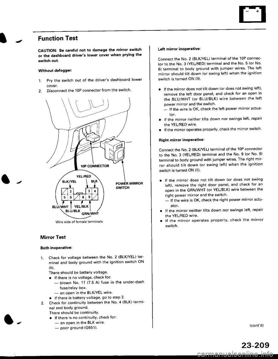
Function Test
CAUTION: Be careful not to damage the mirror switch
or the dashboard drivel's lower covel when prying the
swhch out.
Withoui defogger:
1. Pry the switch out of the driver's dashboard lower
cover.
2. Disconnect the 10P connector from the switch.
lOP CONNECTOR
BLU/WHT
YEL/RED
BLK/YELBLK
4
568
YEL/BLK
POWER MIRRORswtTcH
\:/"*jgil*-(
Wire side of female termanals
Mirror Test
Both inoperative:
1. check for voltage between the No. 2 (BLVYEL) ter
minal and body ground with the ignition switch ON
0 r).
There should be batterY voltage
. If there is no voltage, check for:
- blown No. 17 (7 5 A) fuse in the under-dash
tuse/relay box- an open in the BLK'/YEL wire.
o lf there is battery voltage, go to step 2.
2. Check for continuity between the No 4 (BLK) termi-
nal and body ground.
There should be continuity.
. lf there is no continuity, check for:
- an open in the BLK wire.
- poor ground (G551).
Left mirror inoporalive:
connect the No. 2 {BLK/YEL) terminal of the 10P connec-
tor to the No. 3 (YEURED) terminal and the No 5 (or No
6) terminal to body ground with jumper wires The left
mirror should tilt down (or swing left) when the ignition
switch is turned ON (ll)
. lf the mirror does not tilt down (or does not swing left),
remove the left door panel. and check for an open in
the BLU/WHT (or BLU/BLK) wire between the left
power mirror and the switch
- lf the wire is OK. check the left power mirror actua-
tor.
lf the mirror neither tilts down nor swings left. repair
the YEURED wire.
lf the mirror operates properly, check the mirror switch'
Right mirror inoperative:
Connect the No. 2 (BLK /EL) terminal of the 10P connector
to the No. 3 (YEURED) terminal and the No. 9 (or No 8)
terminal to body ground with jumper wires The right mir-
ror should tilt down (or swing left) when the ignition
switch is turned ON (ll).
. lf the mirror does not tilt down (or does not swlng
left), remove the right door panel. and check for an
open in the GRN/WHT (or YEUBLK) wire between the
right power mirror and the switch.
- lf the wire is OK, check the right power marror actu-
ator.
. lf the mirror neither tilts down nor swings left. repair
the YEURED wire
. lf the mirror operates properly, check the mirror
switch.
(cont'd)
23-209
Page 1729 of 2189

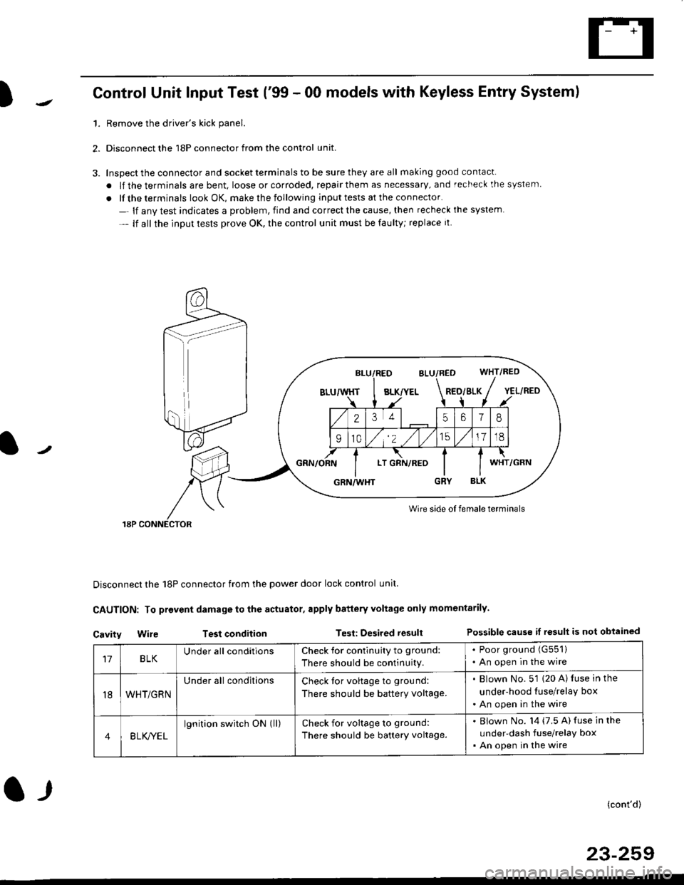
)Control Unit Input Test ('99 - 00 models with Keyless Entry System)
1.Remove the driver's kick panel.
Disconnect the 18P connector from the control unit.
Inspect the connector and socket terminals to be sure they are all making good contacl.
. lf the terminals are bent, loose or corroded, repair them as necessary, and recheck the system
. lf the terminals look OK, make rhe following input tests at the connector.
- lf anv test indicates a problem, find and correct the cause, then recheck ihe system
- lf all the input tests prove OK, the control unit must be faulty; replace it
Wire side oI female terminals
Disconnect the 18P connector from the power door lock control unit.
CAUTION: To provent damage to the actuator, apply battery Yoltage only momentarily.
Cavity Wir€ Test conditionTest: Desired resultPossible cause if result is not obtained
BLK/YELRED/SLK
25618
910/,'2 ,/
'151718
LTWHT
17BLKUnder all conditionsCheck for contlnuity to ground:
There should be continuity.
. Poor ground (G551)
. An open in the wire
t8WHT/GRN
Under all conditionsCheck tor voltage to ground:
There should be battery voltage.
. Blown No. 5'1 (20 A) luse in the
under-hood tuse/relay box
. An open in the wire
4B LK/YEL
lgnition switch ON (ll)check for voltage to ground:
There should be battery voltage.
Blown No. l4 (7.5 A) fuse in the
under-dash fuse/relay box
An open in the wire
(cont'd)
23-259
l-r
Page 1824 of 2189

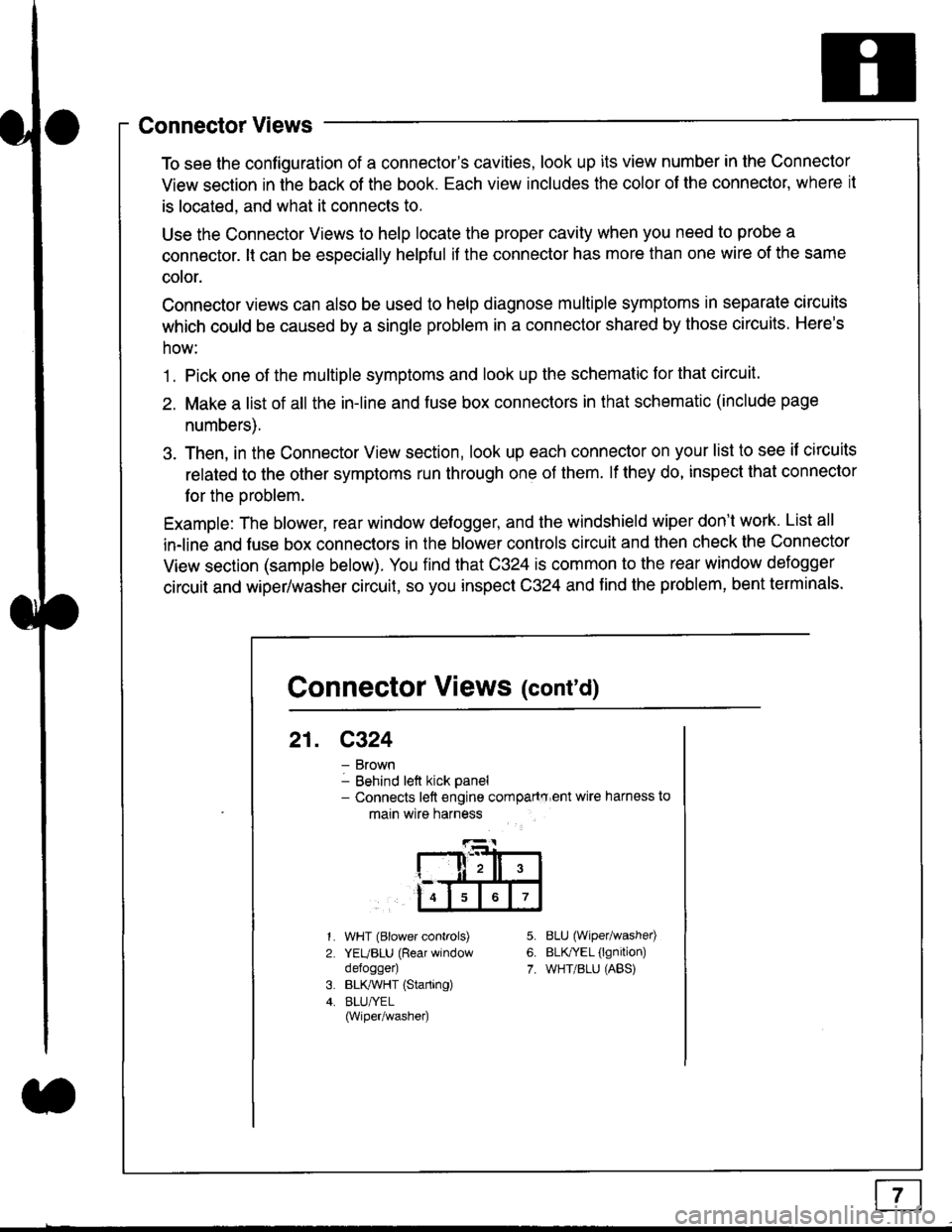
Connector Views
To see the configuration of a connector's cavities, look up its view number in the Connector
View section in the back of the book. Each view includes the color of the connector, where it
is located, and what it connects to.
Use the Connector Views to help locate the proper cavity when you need to probe a
connector. lt can be especially helpful if the connector has more than one wire of the same
cotor.
Connector views can also be used to help diagnose multiple symptoms in separate circuits
which could be caused by a single problem in a connector shared by those circuits. Here's
how:
1. Pick one of the multiple symptoms and look up the schematic for that circuit.
2. Make a list of all the in-line and fuse box connectors in that schematic (include page
numbers).
3. Then, in the Connector View section, look up each connector on your list to see il circuits
related to the other symptoms run through one of them. lf they do, inspect that connector
for the oroblem.
Example: The blower, rear window defogger, and the windshield wiper don't work. List all
in-line and fuse box connectors in the blower controls circuit and then check the Connector
View section (sample below). You find that C324 is common to the rear window defogger
circuit and wiper/washer circuit, so you inspect C324 and find the problem, bent terminals.
5.
6.
7.
1.
2.
WHT (Blower controls)
YEUBLU (Rear window
defogger)
BLK,ryVHT (Starting)
BLU/YEL(Wiper/washe0
8LU (Wiper/washed
BLfiEL (lgnition)
WHT/BLU (ABS)
Connector Views (cont'd)
21. C324
Brown
Behind left kick panel- Connects left engine compartry'ent wire harness to
main wire harness
ll,ll,
567
Page 1851 of 2189

I
I
-- a---
i
i
T
iTl Ill
Irl
ll
tl
MOOECONTROLMOTORPage 61-1' o( 61-2
a
r--1 PowER| | utnnon ;| | swrrcH ;L--J Page l4l 'vtEw 33
- - - '96-'98 models --rand all GXmooers
FUSE 17H€ATENI,/C FEI,AY7,5A
16
c420
vtEw 53
c3s2
r::'l
I uorr I
tl
BLOWERMOTORRELAYPage 60or 60-1PHO|O9 '.a-4.1
I uorr I
tl
A,/C
CLUTCHNELAYPage 62
UNOER-DASHFUSE/RELAYBOX
ia;ij
tl
NAD|ATOR
\
\
I
(NotUsed)
BLK,YEL
't6
BLI(YEL
c440
vlEw 45
BLK/ryEL
'96198
models
'9$'00
mod€ls
I
c?23
vtEw 57 '
ALKTYEL
c723
vlEW 57
atK
2^
1l
ll
HEATERCONTROLPANELPages 61,62-1, and63-1
H EATERCONTROLPANEL
60-1,61-2,62 2,63 2,and 64- 1
TION A/CTHERMOSTATPages 62-1,62-2,63-1,and 63 2PAO|O 82 f96- 98)
NELAYPage 63
UNDER.HOODFUSE/RELAYBOX
ssgj
lTlA/cI I I DIODE
l+,PHoro1t.lEf
Y
r::'r
I uorr I
ll
CONDENSENFANRELAYPage 63
COMPRESSON FAN
-.i--. :
:t:
:l:
:l:
: l,T.il i
:l:
: ,Jl i, r--'t '
:l l:,t t:. L-.J ;; BLOWEn ,, MOTOR. HIGH' RELAY :: Page 60-1 ,, (See S/l\, 'I page 21-3) '
1_ 'ss,'oo lmooets
r--1
tl
ll
RECIRCULATI(CONTROLMOTORPage 61 or 61,2
10-9
Page 1853 of 2189
* = '96-98 models except D1685,'99100 D16Y5 with lVl/T
UNDER-HOODFUSE/RELAYBOX
'98CW - -.
, r--1
:ll:,tt:
: r--J ;, TRANSMISSION ,. CONTROL' MODULE OCM) :' Page 3g-4 ;I PHOIO 121I vlEW 69
I
I
\FUS€ 47aAcx uP
c351
WHT/BLIJ
WHT/BLU
WHT/BLU
18c4'l t
vlEw 60
WHT/ALU
WHT/ALU
11c440
WHT/BLU
10
' WHT/BLU
, 423
c131
vtEw 59
WHT/BITJ
'96-'98
models
I
tl
tl
STEREORADIOTUNERPage 150
'99-'m
modelsmodeB
'99-'�00
models
c723c723
vtEw 57
wHr/atu
810B�21cc10)
tl
ll
HEATERCONTROLPANELPages 60-1,61-2,62-2,and 63-2
vtEw 76
tl
tl
POWERTRAIN oTENGINE CONTROLMODULE(PCM or ECM)
Page 23, 24, ot 25
AUDIOUNITPage 150
tl
HEATERCONTROLPANELPages 62-1and 63'1
10-1 1
Page 1955 of 2189
- '96-'98 Models
From C214 onfacing page.
v
"**il'ifr"e;
S€e FwvofDistrih$on,pags 10'11.
UNDER.HOODFUSE/RELAYBOX
HEATERco TROLPANEL----1 Dimmino
I Clrcult -
L------J
See AitDelivery'l ctte
lrcI
I
I
I
10
HEATERFANswtTcH
INDICATOR
62-1
Page 1956 of 2189
AiC Compressor Gontrols (cont'd)
- '99-'00 Models
From page 62.
v
I*"-ilii.,"r,
ihtli4
BLUAVHT
15
6LUAVHT
UNDER.HOODFUSE/RELAYBOX
Seg Pow6rDistrlbutiofl,pag€ 'l Gl1-c353PHO|O 8
l[,,*
';.!, "'""
,c,/cSwitch switchcommon itput
a,/cTHERMOSTATOlt below3"C (37"F).
THERMISTOR
(
B11A A8A B'IO |'r--:=---I A/C lgnition B€ttery II request input (backup) :
".j:[ru*,,ry "..;X
{;[
vtEW 57
HEATERCONTROLPANEL
l'lCswitch SwitchLgD IEDcodrol cormonGrouod
See AirD€livery,RgarWindowD€foggar
BIK
cl
ORN
c5
GBN
r,/cOt'llndicatof
HEATERPUSHswrTcHEs
t/cSwltch
S€e AirDelivefy,RearWindowDslogg6f
See GroundDist.ibdion,page 1,1-5.
Y
I(
=ffi;
(
.I UNDER.
I HOODi FUSE/I RELAYI Box
IJ
62-2
PHOfO 125