Page 1776 of 2189
Troubleshooting
The SRS Indicator Light Doesn't Go Off -'98 - 00 Models (cont'dl
From page 24 36(D)
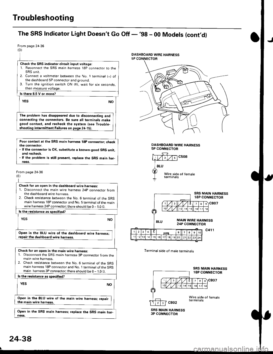
Check the SRS indicetor circuit input voltage:1. Reconnect the SRS main harness l8P connector to theSRS unit.2. Connect a voltmeter between the No. 1 terminal (+) ofthe dashboard 5P connector and ground.3. Turn the ignition switch ON (ll), wait for six seconds,then measure voltage,
ls th€re 8.5 V or more?
YESNO
The problem has disapp€ared due to di3connecting andconneding the connectors. Be su.e all te.minals makegood contact, and recheck the system {see T.ouble-shooting Inte.miftent Failures on page 24-15).
Poor contact et the SRS main harnass 18p connactori checkthe connector,. ll the connector is OK, substitute a known-good SRS unit,and recheck.' It the problem is still present, replace the SRS main haFness.
From page 24-36
Check for an open in the dashboard wir6 harness:1. Disconnect the main wire harness 24P connector fromthe dashboard wire harness.2. Check resistance between the No. 6 terminal of the SRSmain harness 18P connector and No. 5 terminal of the mainwire harness 24P connector; there should be 0 - 1.0 0.
ls the resistance as 3pecitied?
YESNO
Open in the BLU wire ot the dashboard wire harness;repair the dashboard wire harness.
Check tor an open in the main wire haanoss:1. Disconnect the SRS main harness 3P connector from themain wire harness.2. Check resistance between the No. 6 termanal of the SRSmain harness 18P connector and No. 1 terminal of the SRSmain harness 3P connector; there sho!ld be O - l.O 0.
ls the resistance a! specified?
YESNO
Open in the BLU wire of the m.in wire ha.ness: .eoairthe main wire harness.
Open in the SFS main hrrness; replace the SRS main har-ness.
DASHBOARD WIRE HARNESS5P CONNECTOR
c508
Terminal side of male lerminals
SRS MAIN HARNESS18P CONNECTOR
c807
c41 l
SRS MAIN HARNESS18P CONNECTOR
cao2
SRS MAIN HARNESS3P CONNECTOR
24-38
\
DASHBOARD WIRE HARNESS
Page 1802 of 2189
Troubleshooting
DTC 9-2
CAUTION: Whenever the ignition switch is ON 0l), ofhas been turned OFF lor lass than three minutes, becareful not to bump the SRS unit; the airbag(s) couldaccidentally deploy lnd caqse damage or iniuries.
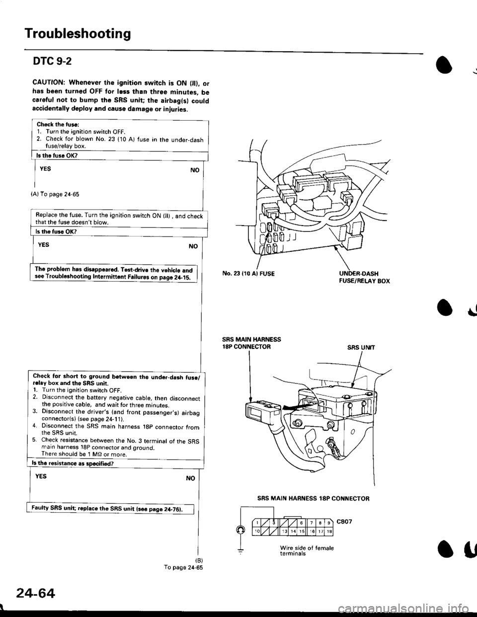
Check the tu.c:1. Turn the ignition switch OFF.2. Check for blown No. 23 (10 A) fuse in the under,dashfuse/relay box.
Replace the tuse. Turn the ignition switch ON lll) , and checkthat the fuse doesn't blow.
Th6 problem hs3 disappe.rod, TGt-dJiv€ the vehiclo and3ee Troublerhooting Intermiftcnt Failuro3 on paqo 2l-15.
Check tol short to ground betwe.n tho unde.-da3h fus./r.ley box and the SRS unit.1. Turn the ignition switch OFF.2. Disconnect the baftery negative cable, then disconnectthe positive cable, and waittorthree minutes.3. Disconnect the driver's (and front passenger,s) airbagconnector(s) (see page 24-11).4. Disconnect the SRS main harness 1gp connector fromthe sRs unit.5. Check resistance between the No. 3 terminal of the SRSmarn harness 18P connector and ground,There should be 1 MO or more.
Feufty SRS unh; rcphce the SRS unit lsee pag.2+761.
(A)To page 24-65
To page 24-65
No. 23 lr0 Al FUSEFUSE/RELAY BOX
!
SRS MAIN HARNESS18P CONNECTORSRS UN'T
24-64
I
SRS MAIN HARNESS 18P CONNECTOR
Otf
Page 1811 of 2189
\
6. Disconnect the connectors from the horn and cruise
control sevresume switches, then remove the steer-
ing wheel nut.
STEERINGNUT
CRUISE CONTROLSET/RESUMESWITCH CONNECTOR
)
HORN CONNECTOR
Remove the steerlng
pulrer.
CABLE REEL2P CONNECYOR
wheel using a steering wheel7.
STEERING WHEEL PULLEF
{Commerciallv_available)
)U
8. Remove the column covers.
Disconnect the 3P connector between the main wire
harness and cable reel sub-harness, 8nd the 2P con-
nector between the cable reel and SRS main harness'
CONNECTORHOLOER
SRS MAIN HARNESS2P CONNECTON
CABLE REEL SUBHARNESS3P CONNECTOR
10. Remove the cable reel from the column {cont'd}
24,73
--/
CABLE REEL
Page 1814 of 2189
SRS Unit
Replacement
CAUTION:
. Betore disconnoqting lny pErt of the SRS wire hal-ness, disconnect th9 airbag conn"ctorlsl.. During installltion or teplacemsnt. do not bump(impact w.cnch, hamm€r stc.l the area noar tho SRSunit.
NOTE:
o Do not damage the SRS unit terminals or connectors.. Do not disassemble the SRS unit; it has no service-able parts,
. Store the SRS unit in a clean, dry a.ea,. Do not use any SRS unit which has be€n subjected towater or shows signs of being dropped or improperlyhandled. such 8s dents, cracks or deformation.
1. Disconnect the bsttery negative cable. then discon-nect the positive cable from the battery, and wait atleast three minutes.
2. Disconnect the airbag connector{s}:
NOTE: When disconnected, the airbag connector isautomatically shorted,
Driver's Side:
. Remove the access panel from the steering wheel.then disconnect the 2P connector between the driv_er's airbag and cable reel (see page 24-11).
Front Passenge/s Side:. Disconnect the 2P connector between the tront oas_senger's airbag and SRS main harness (see page 24-11).
24-76
o\
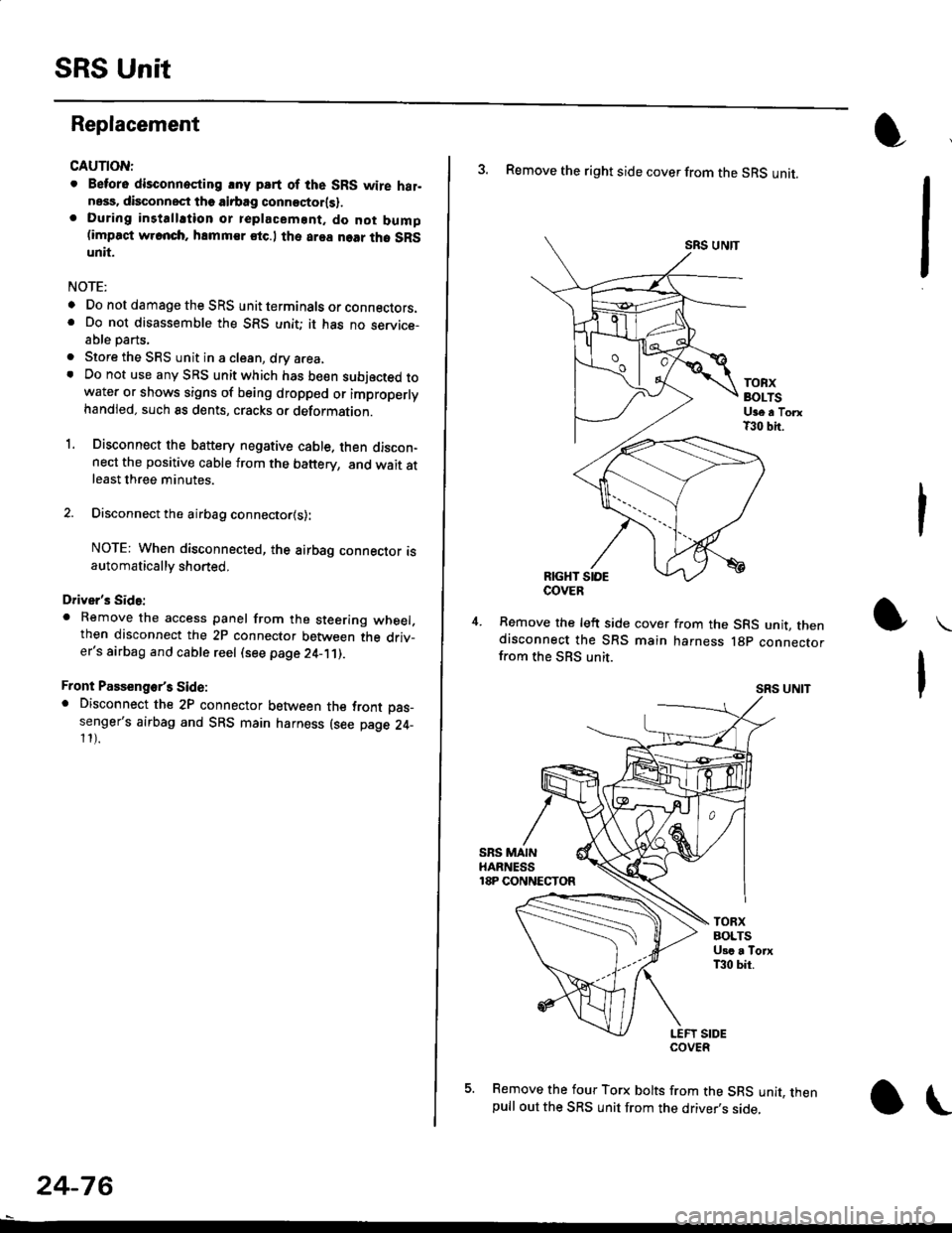
3. Remove the right side cover from the SRS unit.
SRS UNTT
TOBXBOLTSUge a TorxT30 bit.
RIGHT SIOE
Remove the left side cover from the SRS unit, thendisconnect the SRS main harness lgp connectorfrom the SBS unit.
SRS UNIT
5. Remove the four Torx bolts from the SRS unit, thenpull out the SRS unit from the driver,s side,
COVER
Page 1823 of 2189
How To Use This Manual
Component Locations
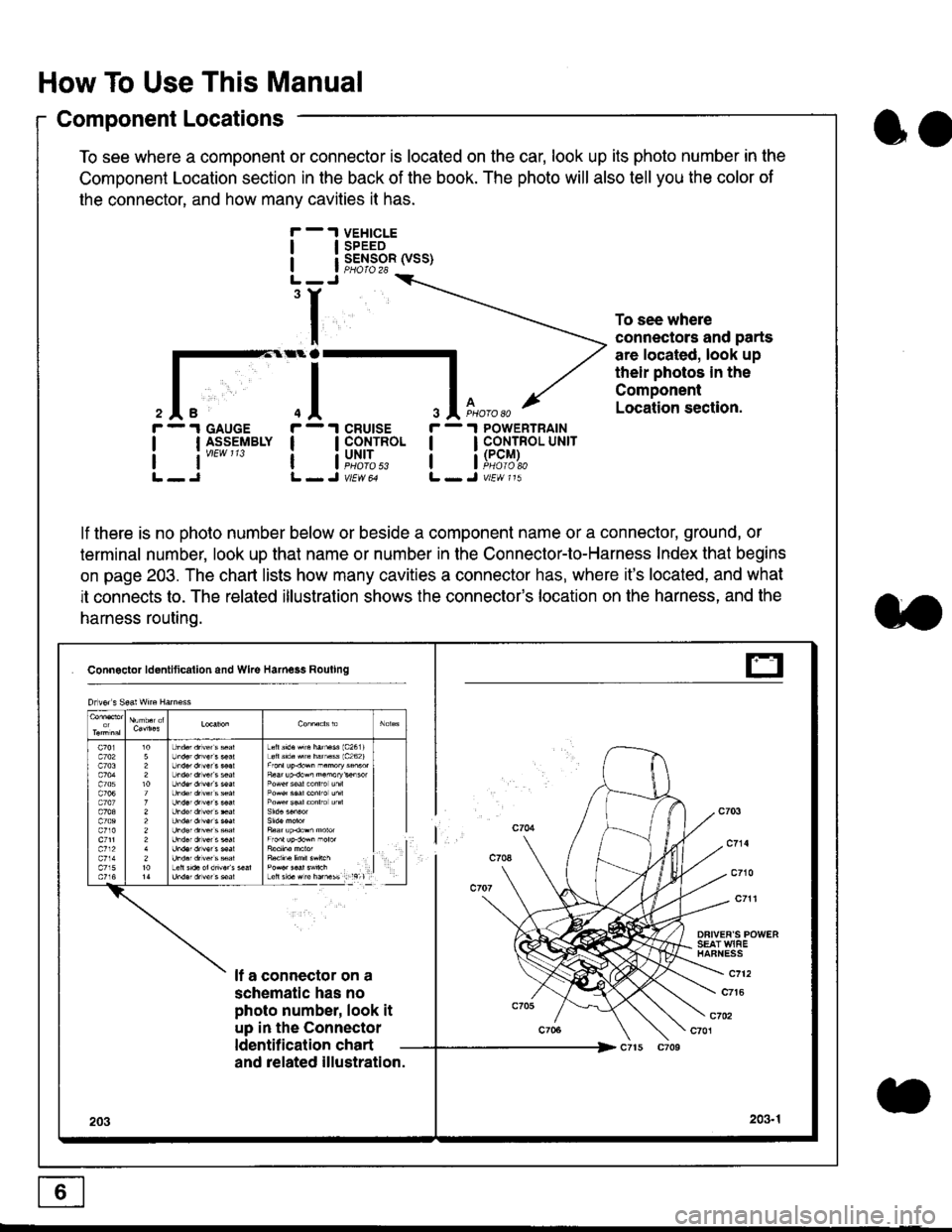
To see where a component or connector is located on the car, look up its photo number in the
Component Location section in the back of the book. The photo will also tell you the color of
the connector, and how many cavities it has.
To see where
connectors and parts
are located, look up
their photos in the
Component
Location section.
I
I
3
r - 1 GAUGE
| | I_S-9_EIBLY
lt''""'
r - 1 cRUtsE
! !fi':*
r - 1 POWERTRAIN
I I CONTROL UNrr
a i[i9#r,
lf there is no photo number below or beside a component name or a connector, ground, or
terminal number, look up that name or number in the Connector-to-Harness Index that begins
on page 203. The chart lists how many cavities a connector has, where it's located, and what
it connects to. The related illustration shows the connector's location on the harness, and the
harness routing.
Connactor ldontlticallon and Wke Harness Rouling
DFIVEF'S POWERSEAT WIAEHAFNESS
It a connector on a
schematic has no
photo number, look it
up in the Connector
ldentilication chart
c712
c7t6
c702c701
and related illustration.
203203.1
Drlvor s Sea! wne Harn€ss
Lefts'd.Hrc hatu$ 1c2611Loft s'd. src hamass 1c262)
F6ar up.dow^ n.morykisor
l
E
oo
Page 1824 of 2189
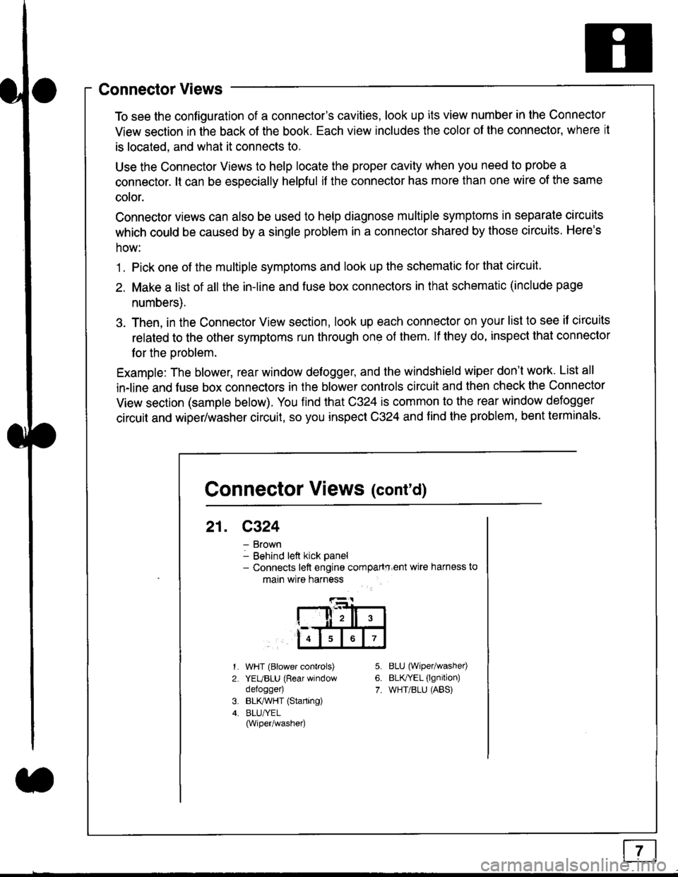
Connector Views
To see the configuration of a connector's cavities, look up its view number in the Connector
View section in the back of the book. Each view includes the color of the connector, where it
is located, and what it connects to.
Use the Connector Views to help locate the proper cavity when you need to probe a
connector. lt can be especially helpful if the connector has more than one wire of the same
cotor.
Connector views can also be used to help diagnose multiple symptoms in separate circuits
which could be caused by a single problem in a connector shared by those circuits. Here's
how:
1. Pick one of the multiple symptoms and look up the schematic for that circuit.
2. Make a list of all the in-line and fuse box connectors in that schematic (include page
numbers).
3. Then, in the Connector View section, look up each connector on your list to see il circuits
related to the other symptoms run through one of them. lf they do, inspect that connector
for the oroblem.
Example: The blower, rear window defogger, and the windshield wiper don't work. List all
in-line and fuse box connectors in the blower controls circuit and then check the Connector
View section (sample below). You find that C324 is common to the rear window defogger
circuit and wiper/washer circuit, so you inspect C324 and find the problem, bent terminals.
5.
6.
7.
1.
2.
WHT (Blower controls)
YEUBLU (Rear window
defogger)
BLK,ryVHT (Starting)
BLU/YEL(Wiper/washe0
8LU (Wiper/washed
BLfiEL (lgnition)
WHT/BLU (ABS)
Connector Views (cont'd)
21. C324
Brown
Behind left kick panel- Connects left engine compartry'ent wire harness to
main wire harness
ll,ll,
567
Page 1826 of 2189
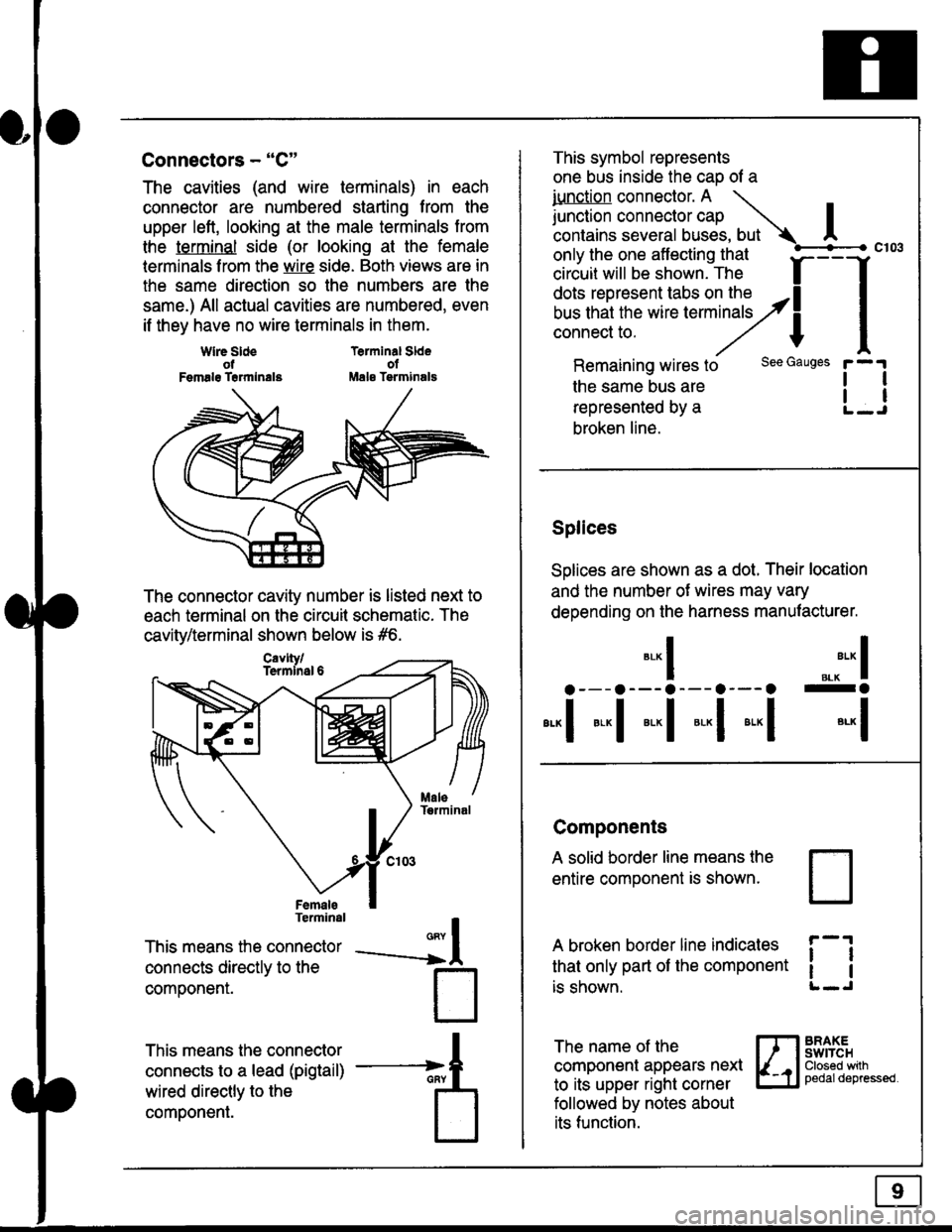
Connectors - "C"
The cavities (and wire terminals) in each
connector are numbered starting from the
upper left, looking at the male terminals trom
the terminal side (or looking at the female
lerminals f rom the wire side. Both views are in
the same direction so the numbers are the
same.) All actual cavities are numbered, even
if they have no wire terminals in them.
Terminal SldeolMale Tsrminals
{
T
_A
Wlre SldeotFemalg Trrmlnala
The connector cavity number is listed next to
each terminal on the circuit schematic. The
cavity/terminal shown below is #6.
Terminal
This means the connector
connects directly to the
componenr.
This means the connector
connects to a lead (pigtail)
wired directly to the
component.
Cavlty/Termlnsl 6
only the one affecting that
ciriuit will be shown. The f
--f
!!*!"*F"#fi5'�;,Hy4
I
Remaining wires to
the same bus are
represented by a
broken line.
The name of the
component appears next
to its upper right corner
followed by notes about
its function.
This symbol represents
one bus inside the cao of a
iunction connector. A \
lr"ctb. connectorcap |contains several buses, but Ac103
tl
tl
*-
I ",.-"* I
a---a---a--- a--- o -a
*"1 *-l *-l *-l *"1 *-l
See Gauges
Splices
Solices are shown as a dot. Their location
and the number of wires may vary
depending on the harness manufacturer.
Components
A solid border line means the
entire component is shown.
A broken border line indicales
that only part of the component
is shown.
t_J
ll
ll
BRAXEswtTcHClosed wilhpedaldepressed.
Page 1831 of 2189
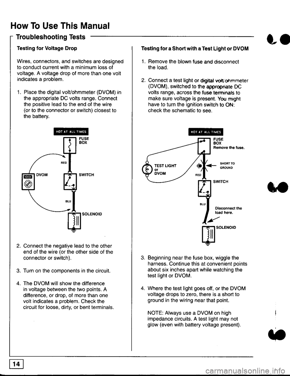
How To Use This Manual
Troubleshooting Tests
Testing for Voltage Drop
Wires, connectors, and switches are designed
to conduct current wilh a minimum loss of
voltage. A voltage drop of more than one volt
indicates a Droblem.
'1. Place the digital volVohmmeter (DVOM) in
the appropriate DC volts range. Connect
the positive lead to the end of the wire
(or to the connector or switch) closest to
the bafterv.
Connect the negative lead to the other
end of the wire (or the other side of the
connector or switch).
Turn on the components in the circuit.
The DVOM will show the difference
in voltage between the two points. A
difference, or drop, of more than one
volt indicates a oroblem. Check the
circuit for loose, dirty, or bent terminals.
co
Testing lor a Short with a Test Light or DVOM
1. Remove the blown fuse and disconnect
the load.
2. Connect a test light or digital
oltr'ohmmeter
(DVOM), switched to the appropnare DC
volts range, across the tuse lerminals to
make sure voltage is present. You might
have to turn the ignition switch to ON:
check the schematic to see.
<-s80RT TOGFOUNO
Disconnecl lheload here.
Beginning near the luse box, wiggle the
harness. Continue this at convenient ooints
about six inches apart while watching the
test light or DVOM.
Where the test light goes off, or the DVOM
voltage drops to zero, there is a short to
ground in the wiring near that point.
NOTE: Always use a DVOM on high
impedance circuits. A test light may not
glow (even with battery voltage present).
3'�'
ffito.'"o'o
.t.
TEST LIGHTolDVOM