Page 1566 of 2189
Starting System
Starter Test lcont'dl
Ch€ck tor Wear and Damage
The starter should crank the engine smoothly and
steadily, lf the starter engages. but cranks the engine
erratically, remove it, and inspect the starter drive gear
and torque converter or flywheel ring gear for damage.
. Check the drive gear overrunning clutch for binding
or slipping when the armature is rotated with the
drive gear held,- lf damaged. replace the gears.
Check Cranking Voltsge and Curr€nt Draw
Cranking voltage should be no less than 8.5 volts.
Current draw should be no more than 350 amperes.
lf cranking voltage is too low, or current draw too high,
check for;
. dead or low batterv.
. open circuit in starter armature commutator seg-
ments,
. starter armature dragging.
. shorted armature winding.
o excessive drag in engine.
Check Cranking rpm
Engine speed during cranking should be above 100 rpm,
lf speed is too low, check for:
. loose battery or stanerterminals.
. excessively worn starter brushes,
. open circuit in commutator segments.
o dirty or damaged helical spline or drive gear.
. defective drive gear overrunning clutch.
Check Siarter Disengag€ment
With the shift lever in El or @ position (A/T) or with the
clutch pedal depressed (M/T), turn the ignition switch to
START (lll), and release to ON (ll).
The starter drive gear should disengage from the torque
converter or flywheel ring gear when you release the
Key.
lf the drive gear hangs up on the torque converter or fly-
wheel ring gear, check for:
. solenoid plunger and switch malfunction,
. dirty drive gear assembly or damaged overrunning
clutch.
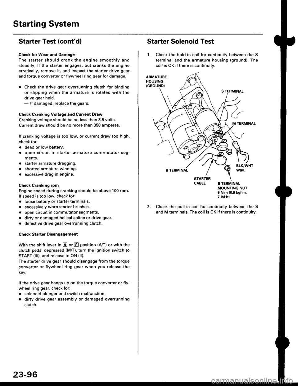
Starter Solenoid Test
1. Check the hold-in coil for continuitv between the S
terminal and the armature housing (ground). The
coil is OK if there is continuitv,
ARMATUREHOUSING(GROUND)
S TERMINAL
M TERMINAL
B TERMINAL
STARTERCAELE B TERMINALMOUNTING NUTI N.m {0.9 kgf.m,7 tbf.ft)
Check the pull-in coil for continuity between the S
and M terminals. The coil is OK if there is continuity.
Page 1575 of 2189
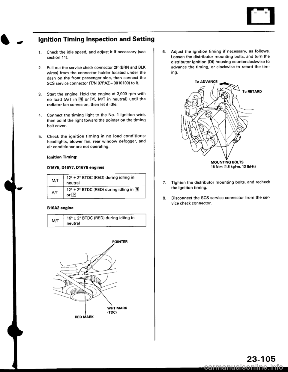
-lgnition Timing Inspection and Setting
1.Check the idle speed, and adjust it it necessary (see
section 'l '1 ).
Pull out the service check connector 2P (BRN and BLK
wires) from the connector holder located under the
dash on the front passenger side, then connect the
SCS service connector (T/N 07PAZ - 0010'100) to it.
Start the engine. Hold the engine at 3.000 rpm with
no load {A,/T in E or E. M/T in neutral) until the
radiator fan comes on, then let it idle.
Connect the timing light to the No. 1 ignition wire,
then point the light toward the pointer on the timing
belt cover.
Check the ignition timing in no load conditions:
headlights. blower fan, rear window defogger, and
air conditioner are not operating.
lgnhion Timing:
D15Y5. D16Y7, Dl6Yg engines
816A2 engine
MIT16" 12' BTDC (RED) during idling in
neutral
M/T12't 2" BTDC (RED) during idling in
neutral
l2'r 2" BTDC {RED) during idling in S
orE
POINTEB
RED MARK
23-105
ro ADVANCE -<;,
6. Adjust the ignition timing if necessary, as follows.
Loosen the distributor mounting bolts. and turn the
distributor ignition (Dl) housing counterclockwise to
advance the timing, or clockwise to retard the tim-
ing.
MOUNTING BOLTS18 N'm (1.8 kgfm, 13lblftl
Tighten the distributor mounting bolts, and recheck
the ignition timing.
Disconnect the SCS service connector from the ser-
vice check connector.
7.
Page 1586 of 2189
Charging System
Troubleshooting (cont'd)
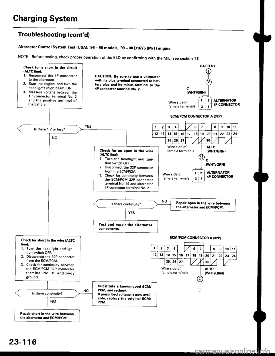
Alternator Control System Test (USA): ,96 - 98 modets, ,99 _ 00 Dl6y5 (M/Tl engine
NorE: Before testing. check proper operation of the ELD by confirming with the MrL {see section r 1).
BATTERY
CAUTION: Be 3ure to use a voltmot€.with its plus terminal connected to b.t-tery plus and its minus terminal to the{P connectoi tgmrinal No. 2.c
{WHT/GRNt
Wire side oIfemale terminals
ALTERNATOR.P CONNECTOB
Check for a 3hort in the circuitIALTC linel:1. Reconnect the 4P connectorto the alternator,2. Stan the engine, and turn theheadlights {high beam) ON.3. Measure voltage between the4P connector terminal No. 2and the positive terminal ofthe battery.
ls there 1V or less?
Check for rn opon in tha wire(ALTC linol:1. Turn the headlight and igni-tion switch OFF.2. Disconnect the 32P connectortrom the ECM/PCN4.3. Check tor continuity betweenthe ECM/PCM 32P connectorterminal No. 19 and alternator4P connector terminal No. 2.
Bspair open in thg wire lrstweenthe rhern.tor .nd ECM/PCM.
Check for short in the wire (ALTClinel:1. Turn the headlight and ignition switch OFF.2. Disconnect the 32P connectortrom the ECM/PCM.3. Check tor continuity betweenthe ECM/PCM 32P connectorterminal No. 19 and bodyground.
Subslitute a known-good ECM/PCM, .nd .och6ck.It p.escribod vohago i! now avail-able, replace the original ECM/PCM.
Ropair 3hort in the wiro betweonthe ahe.nator and ECM/PCM.
ECM/PCM CONNECTOR A I32PI
'Ia18I1011
121314151718t9
7
202'l2221
262730
Wire side offemale terminalsALTC(WHT/GRNI
c{WHT/GRNI
ALTERNATORWire side oIfemale terminals
([l
T
12
1
ECM/PCM CONNECTOB A (32PI
I23478910t1
1213 14151617182021222321
262730
Wire side of I AITCfemate terminats
A
(WHT/GRN|
23-116
Page 1587 of 2189
-
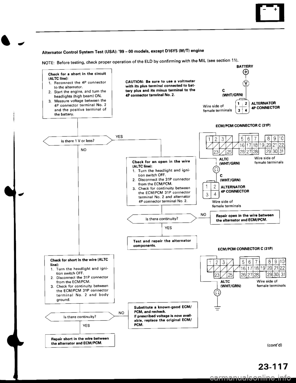
Alternator Control System Test {USA}: '99 - 0O models, except Dl6Y5 {M/T} engine
NOTE: Before testing, check proper operation ofthe ELD by confirming with the MIL (see section 11)'
BATTERY
CAUTION: Be sura lo use a voltmeter
with its plus te.minal conneqted io bat-
tery plus and it3 minus tgrminal to ths
4P connoctot tomrinal No. 2.
Wire side of
female terminals
c(WHT/GRNI
wire side offemale terminals
ALTERNATOR.P CONNECTOR
ECM/PCM CONNECTOR C 13lPI
ECM/PCM CONNECTOR C (31PI
(cont'd)
23-117
Check lor a sho.t in the circuit
{ALTC line):1, Beconnect the 4P connector
to the alternator.
2. Start the engine, and turn the
headlights (high beam) ON.
3. Measure voltage between the
4P connector terminal No. 2
and the Positive terminal of
the battery.
ls there 1 V or less?
Chcck for rn opon in the wire(ALTC lin6l:1. Turn the headlight and igni-
tion switch OFF
2. Disconnect the 31P connector
trom the ECM/PCM.
3. Check for continuity betlveen
the ECM/PCM 31P connectorterminal No. 2 and alternator
4P connector terminal No. 2
Repair opcn in the wire botweon
the alternstoi.nd ECM/PCM.ls there continuity?
Check tor short in the wire IALTC
line):1. Turn the headlight and igni-
tion switch OFF2. Disconnect the 31P connector
from the ECM/PCM.
3. Check for continuity between
the ECM/PCM 31P connector
terminal No. 2 and body
ground.
Substitute a known'good ECM/
PCM, and recheck.It prscribed voltagg is now avail'
abl€, replace tho original ECM/
PCM.
Raoair short in the wite between
the alle.nator and ECM/PCM,
1235618I10
/11611lo191 zo2122
23252621?82930JI
ALTC Wire side of(WHT/GRN) female terminals
o
Page 1589 of 2189
The charging system is OK.ls the amperage 50 A or more?
Alternator/Regulator Test-4:
With the engine sPeed still at
2,000 rpm, fulltieid the alternator.
J
From previous page
CAUTION: The voltage will rise quickly when the allGrnator is flll-fielded Do not ellow
the vollage to exceed 18 V; il may damage the electrical syslem
NOTE: Attach a probe to a VAT 40 full field test lead, and insert the probe into the full field
access hole at the back of the alternator' Switch the field selector to the "A (GroLrnd)" posi
tion momentarilV, and check the amperage readlng
23-119
Page 1610 of 2189
Vehicle Speed Sensor (VSSI
Troubleshooting
Before testing, inspect the No. 15 (7.5 A) fuse in the under-dash fuse/relay box.
TEST HARNESSOTLAJ _ PT3O2OAREO TEST HARNESSCLIP
PROTECTIVETAPE
TEST HARNESSOTLA' . PT3O2OA
(To next page)
Test the BLK wire:1. Disconnect the 3P connectorfrom the vehicle speed sensor(vss).
2. Connect the test harness(07LAJ PT30200) only to theengine wire harness,3. Connect the RED test harnessclip to the positive probe of a
4. Check for continuity betweenthe RED test harness clip andbody ground.
Repair opon in the BLK wireb€twe€n the VSS and G101.ls there continuity?
Te3t the BLK/YEL wire:1. Connect the WHT test harnessclip to the positive probe of avoltmeter, and connectthe REDtest harness clip to the negativeprobe.2. Turn the ignition switch ON {ll).
Repair open in iho BLK/YEL wirebetween the VSS and the under-d6sh tuse/relav box.
vss
GRN TEST HARNESS
RED TEST HARNESS
WHT TEST HARNESS CLIP
23-140
Page 1625 of 2189
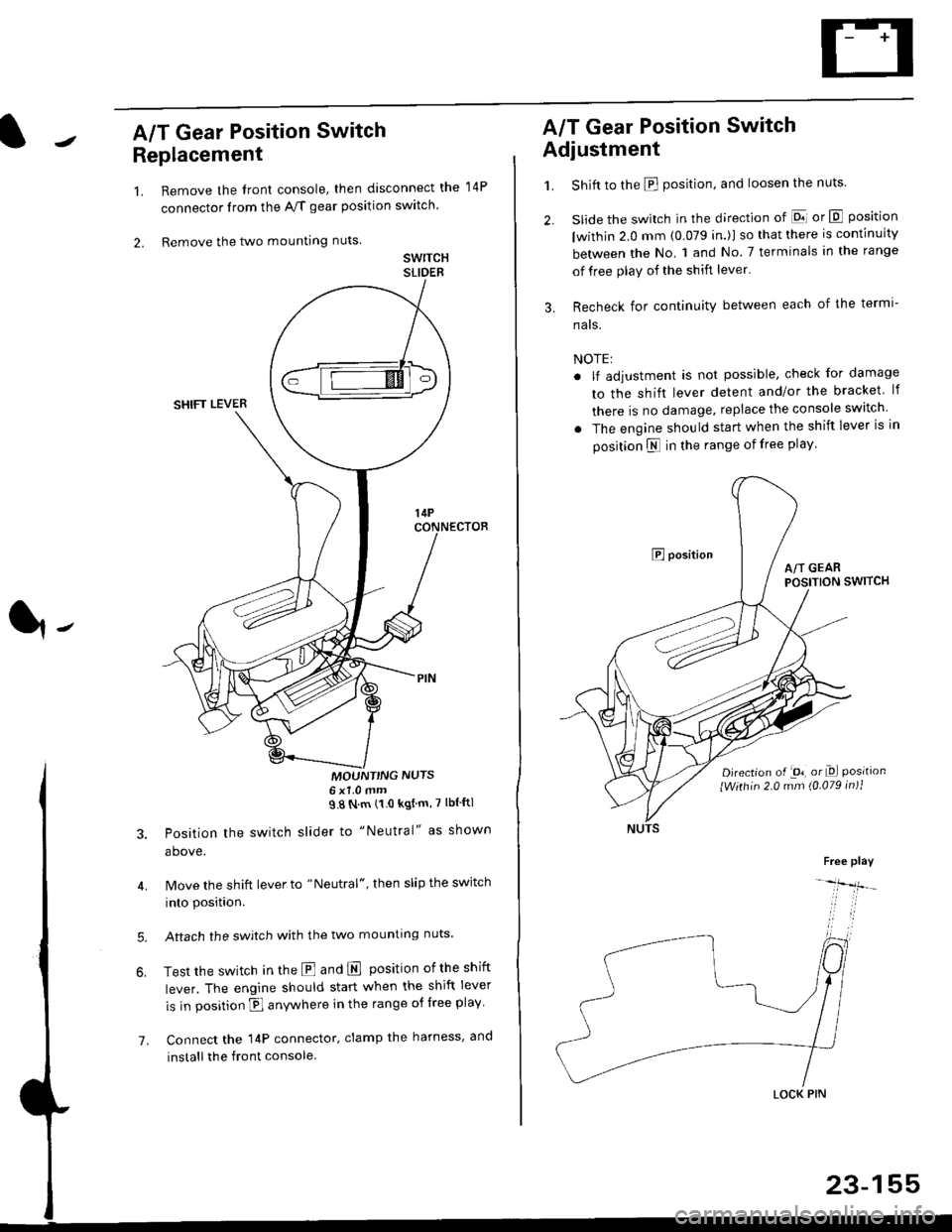
A/T Gear Position Switch
Replacement
1.
2.
7.
Remove the front console, then disconnect the
connector from the A/f gear position swltch
Remove the two mounting nuts
swrTcHSLIDEB
MOUNT'NG NUTS6x1 0mm98Nm(10kgtm'7lblftl
Position the switch slider to "Neutral" as shown
above.
Move the shift lever to "Neutral", then slip the switch
into position.
Aftach the swjtch with the two mounting nuts.
Test the switch in the E and E position ofthe shift
lever. The engine should start when the shift lever
is in position fl anywhere in the range of free play
Connect the 14P connector, clamp the harness, and
install the front console
14P
A/T Gear Position Switch
Adjustment
1.
3.
Shift to the E position, and loosen the nuts.
slide the switch in the direction of El or E position
lwithin 2.0 mm (0.079 in.)l so that there is continuity
between the No. 1 and No 7 terminals in the range
of free play of the shift lever'
Recheck for continuity between each of the termi-
nats.
NOTE:
. lf adjustment is not possible, check for damage
to the shift lever detent and/or the bracket lf
there is no damage. replace the console switch
. The engine should start when the shift lever is in
position N in the range of free play
E positionA/T GEARPOSITION SWITCH
Djrection of -on, or Dl Positionlwithin 2.0 mm (0.079 in)1
Free play
-lfr-
LOCK PIN
23-155
Page 1718 of 2189
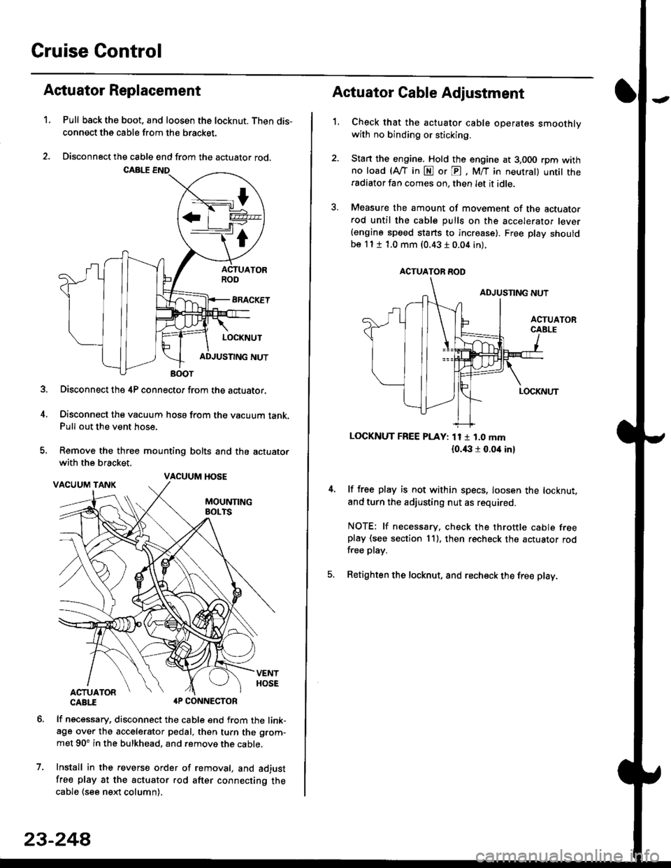
Cruise Control
t
D=
t
Astuator Replacement
1.Pull back the boot, and loosen the locknut. Then dis-
connect the cable from the bracket.
Disconnect the cable end from the actuator rod.
Disconnect the 4P connector from the actuator.
Disconnect the vacuum hosa from the vacuum tank.Pull out the vent hose.
Remove the three mounting bolts and the actuator
with the bracket.
CABTI aP CONNECTOR
lf necessary, disconnect the cable end from the link-age over the accelerator pedal, then turn the grom-
met 90' in the bulkhead, and remove the cable,
Install in the revers€ order of removal, and adjust
free play at the actuator rod after connecting thecable (see ne)d column).
7.
VACUUM HOSE
23-244
1.
Actuator Cable Adjustment
Check that the actuator cable operates smoothlywith no binding or sticking.
Stan the engine. Hold the engine at 3,000 rpm withno load (Afl'in N or E, M/T in neutral) untit theradiator fan comes on, then let it idle.
Measure the amount of movement of the actuato.rod until the cable pulls on the accelerator lever(engine speed starts to increase). Free Dlay shouldbe 11 t 1.0 mm (0.43 I 0.04 in).
LOCKNUT FREE PLAY: 11 1 1.0 mm
{o.i|:l r 0.oit in}
lf free play is not within specs, loosen the locknut,
and turn the adjusting nut as required.
NOTE: lf necessary. check the throttle cable freeplay (see section 11). then recheck the actuator rodfree play.
Retighten the locknut, and recheck the free play.
ACTUATOR ROD