Page 823 of 2189

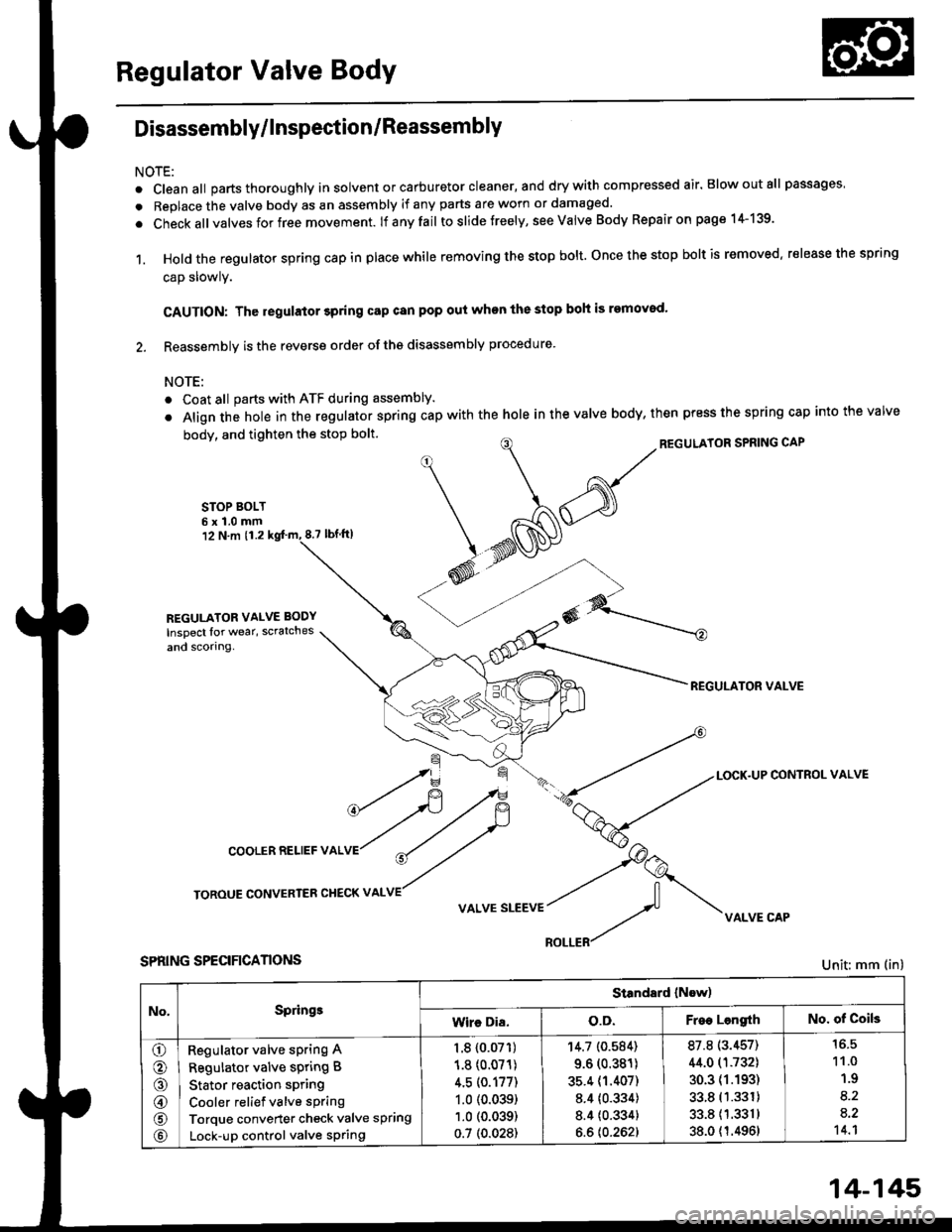
Regulator Valve Body
Disassembly/lnspection/Reassembly
NOTE:
. cleanall parts thoroughly in solvent or carburetor cleaner, and drywith compressed air. Blowoutall passages
. Replace the valve body as an assembly if any parts are worn or damaged.
. check allvalves for free movement. lf anyfail toslidetreely, see valve Body Repairon page 1+139.
1. Hold the regulator spring cap in place while removing the stop bolt. once the stop bolt is removed. release the spring
cap slowly.
CAUTION: The regulator 3pring cap can pop out when the stop boh is removod'
2. Reassembly is the reverse order ofths disassembly procedure.
NOTE:
o Coat all parts with ATF during assembly.
. Align the hole in the regulator spring cap with the hole in the valve body, then press the spring cap into the valve
body, and tighten the stop bolt.
STOP BOLT6x1.0mm12 N.m 11.28.7 tbf.lrl
^/^'ou*'oRsPRrNGcAP
*N@
REGULATOR VALVE
\=f -.-*
*fi /F { a-tLocK.uPcoNrRoLvALVE
cooLERRELlEFvALVr"r?
ry
roRouE coNvERrER cHEcKv ^LvE//
v ^r* "r**::f vi{LvE cAp
SPRING SPECIFICANONS
REGULATOR VALVE BODY
Inspect lor wear, scratches
and scorlng.
Unit: mm (in)
No,Springe
Standard (Now)
Wire Dia.o.D.Free LengrthNo. of Coils
o
o
@
@
@
Regulator valve sPring A
Regulator valve spring B
Stator reaction spring
Cooler relief valve spring
Torque converter check valve spring
Lock-up control valve sPring
1.8 {0.07'�r)
1.8 (0.071)
4.5 (0.177)
1.0 (0.039)
1.0 (0.039)
0.7 (0.028)
'r4.7 (0.584)
9.6 (0.381)
35.4 (1.407)
8.4 {0.334)
8.4 {0.334}
6.6 {0.262}
87.8 (3.457)
44.0 (1.732)
30.3 (1.193)
33.8 (1.331)
33.811.3311
38.0 {1.4961
11.0
1.9
8.2
a.2't 4.1
14-145
Page 824 of 2189

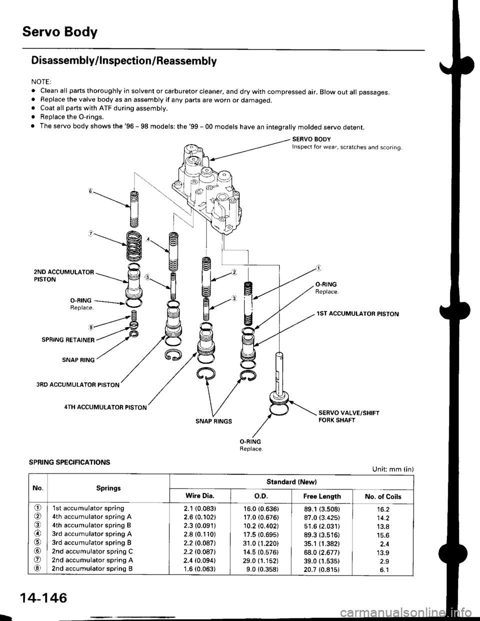
Servo Body
Disassembly/lnspection/Reassembly
NOTEI
. clean all parts thoroughly in solvent or carburetor cleaner, and dry with compressed air. Blow out all passages.. Replace the valve body as an assembly if any parts are worn or damaged.. Coat all parts with ATF during assembly.
. Replace the O-rings.
. The servo body shows the '96 - 98 models: the '99 - 00 models have an integrally molded servo detent.
SERVO BODYInspect for wear, scratches and scoring.
,______.- g
1l
v
"-------'g
ZruO lCCUr,irUr-nrOn ---rrr___-p
n\='l
3,ii11---------*5
^rrr4
I
O.RINGReplace.
3RO ACCUMULATOR PISTON
4TH ACCUMULATOR PISTON
SPRING SPECIFICATIONS
SNAP RINGS
1ST ACCUMULATOR PISTON
Unit: mm (in)
No.SpringsStandard {New)
Wire Dia.o.D.Free LengthNo. of Coils
o(a
@)
o
@
'I st accumulator spring
4th accumulator spring A
4th accumulator spring B
3rd accumulator spring A
3rd accumulator spring B
2nd accumulator spring C
2nd accumulator spring A
2nd accumulator spring B
2.1 (0.083)
2.6 (0.102)
2.3 (0.091)
2.8 (0.110)
2.210.0871
2.2 t0.0a7l
2.4 (0.094)'1.6 (0.063)
16.0 (0.636)
17.0 (0.676)
10.2lo.402J
17.5 (0.695)
31.0 11.220)
14.5 (0.576)
29.0 (1.152)
9.0 (0.358)
89.1 (3.s08)
87.0 (3.425)
51.6 (2.031)
89.3 (3.516)
35.1 (1.382)
68.012.677)
39.0 (1.535)
20.7 (0.815)
14.2
13.8
'13.9
L
14-146
Page 825 of 2189
Lock-up Valve BodY
Disassembly/lnspection/Reassembly
NOTE:
. Clean all pans thoroughly in solvent or carburetor cleaner' and dry with compressed air' Blow out all passages'
a Replace the valve body as an assembly if any parts are worn or d€maged'
. Checkall valves for free movement ttanytaitio stlae freely' see Valve Body Repairon page 14-'139'
. Coat all parts with ATF during assembly
LOCK.UP VALVE BODY
Inspect for wear, scratchesand sconng.
VALVE CAP
LOCK-UP TIMING VAL
SPRING SPECIFICATIONSUnit: mm (in)
73.1 t2.902J
ao.7 13.'17717.6 (0.302)
8.1 (0.319)Lock-up shift valve sPrang
Lock-up timing valve sPrlng
14-147
Page 826 of 2189

Mainshaft
Disassembly/lnspestion/Reassembly
NOTE:
. Lubricate all parts with ATF during reassembly..Inspectthethrustneedlebearingsandtheneedlebearingsforgallingandroughmovement,
. Before installing the O-rings, wrap the shaft splines with tape to prevent damaging the O_rings.. Locknut has left-hand threads.
LOCKNUT {FLANGE NUTI21 x 1.25 mm78 N.m (8.0 kgl.m,58 lbt.fttReplace.Left-hand threadsSNAP RINGCONICAL SPRING WASHERReolace.
lST CLUTCHASSEMBLYTHRUST WASHER
THRUST NEEOI.EBEARING
4TH GEAN
O-RINGSReplace.
THRUST WASHER
THRUST NEEDLEBEARING
MAINSHAFTCheck splines for excessivewear and oamage.Check bearing surtace for scoring,scratches and excessive wear.
BEARINGBEARINGS
THRUST NEEDLEBEABING
4TH GEAR COLLAR
2ND/4TH CLUTCHASSEMBLY
THRUST NEEDLEEEARING
2NO GEAB
NEEDLE BEABING
THRUST NEEDLEBEARING
1ST GEAR
1ST GEARCOLLAR
TRANSMISSIONHOUSING BEARING
O-RINGSReplace.
THRUST WASHER, 36.5 x 55 mmSelective part.
SEALING RINGS,35 mm
Install the sealing ringmating faces as shown,
RING,29 mm
NEEDLE BEARING
SET RING
14-148
Page 829 of 2189
Countershaft
Disassembly/lnspection/Reassembly
NOTE:
. Lubricate all parts with ATF before reassembly'
. tnrp"",,n",t -"t needle bearings and the needle bearings for galling and rough movement'
. Before installing the O-rings. wrap the shaft splines with tape to prevent damaging the O-rings
. Locknut has left-hand threads
LOCKNUT (FLANGE NUT}
23 x 1.25 mm103 N.m
{10.5 kgf'm, 75.9 lbf'tt)
Replace.Left'handlhreads
CONTCAL SPRING
WASHERReplace.
GEAR
CLUTCH
1ST GEAR
BEARING
lST GEAR COLLAR
TRANSMISSIONHOUSING BEARING
REVERSE GEAR
NEEDLEBEARING
SELECTOR
SELECTOR
4TH GEAR
NEEDLE BEARING
DISTANCE COLLAS,
28 mmSelective pa .
COUNYERSHAFTCheck splines lor excesslve
wear and damage
2'{D GEAR
THRUST NEEDLEBEARING
3RD GEAB
NEEDLE BEARING
3RD GEAR COLLAR
THRUST NEEDLE EEARING
SPLINEO WASHER
3RD CLUTCH ASSEMBLY
Check bearing surface for scoring'
scratches and excessive wear'
Replace.
1+151
Page 830 of 2189
Countershaft
Disassembly/Reassembly
1. Using a hydraulic press, press out the countershaftwhile supporting 4th gear.
NOTE: Place an attachment between the press andthe countershaft to prevent damage to the shaft.
CAUTION: Do not allow the countershaft to fall andhit the g.ound when pressed clear.
14-152
2. Assemble the parts on the countershaft as shownoetow.
NOTE;
. Lubricate all parts with ATF during assembly.. Before installing the O-rings, wrap the shaft splineswith tape to prevent damaging the O_rings.
4TH GEAR
NEEDLE EEARING
DISTANCE COLLAR, 28 mmSelective part.
2ND GEAR
THRUST NEEOLE BEARING
3RD GEAR
NEEDI.E EEARING
3RO GEAR COLLAR
THRUST NE€OLE BEARING
SPLINED WASHER
3RD CLUTCH ASSEMBLY
O.RINGSReplace.
COUNTERSHAFT
Page 835 of 2189
SNAP RING
2NDi4TH CLUTCH
SNAP RING
SPRING RETAINER
RETURN SPRING
DISC SPRING
CHECK VALVE
O.RINGSReplace.4TH CLUTCH DRUM
CLUTCH PISTON
CLUTCH PLATESStandardthickness: O-RINGS2.0 mm {0.079 in) Replace.
SNAP RING
14-157
Page 840 of 2189
Clutch
Reassembly
NOTE:
. Clean all parts thoroughly in solvent or carburetor
a
cleaner, and dry them with compressed air.
Blow out all passages.
Lubricate all parts with ATF before reassembly.
Inspect the check valve; if it's loose, replace the pis-
to n.
1.
CHECK VALVE
2. Install new O-rings on the clutch piston.
O RINGS
PISTON
-
14-162
3. Install the piston in the clutch drum, Apply pressure
and rotate to ensure proper seating,
NOTE: Lubricate the piston O-ring with ATF beforeinstalling.
CAUTION: Do not pinch the O-ring by insta ing thepiston with too much force.
CLUTCII DRUM
Install the return spring and spring retainer, andposition the snap ring on the retainer.
CLUTCI{ DRUM