Page 1535 of 2189

lr-
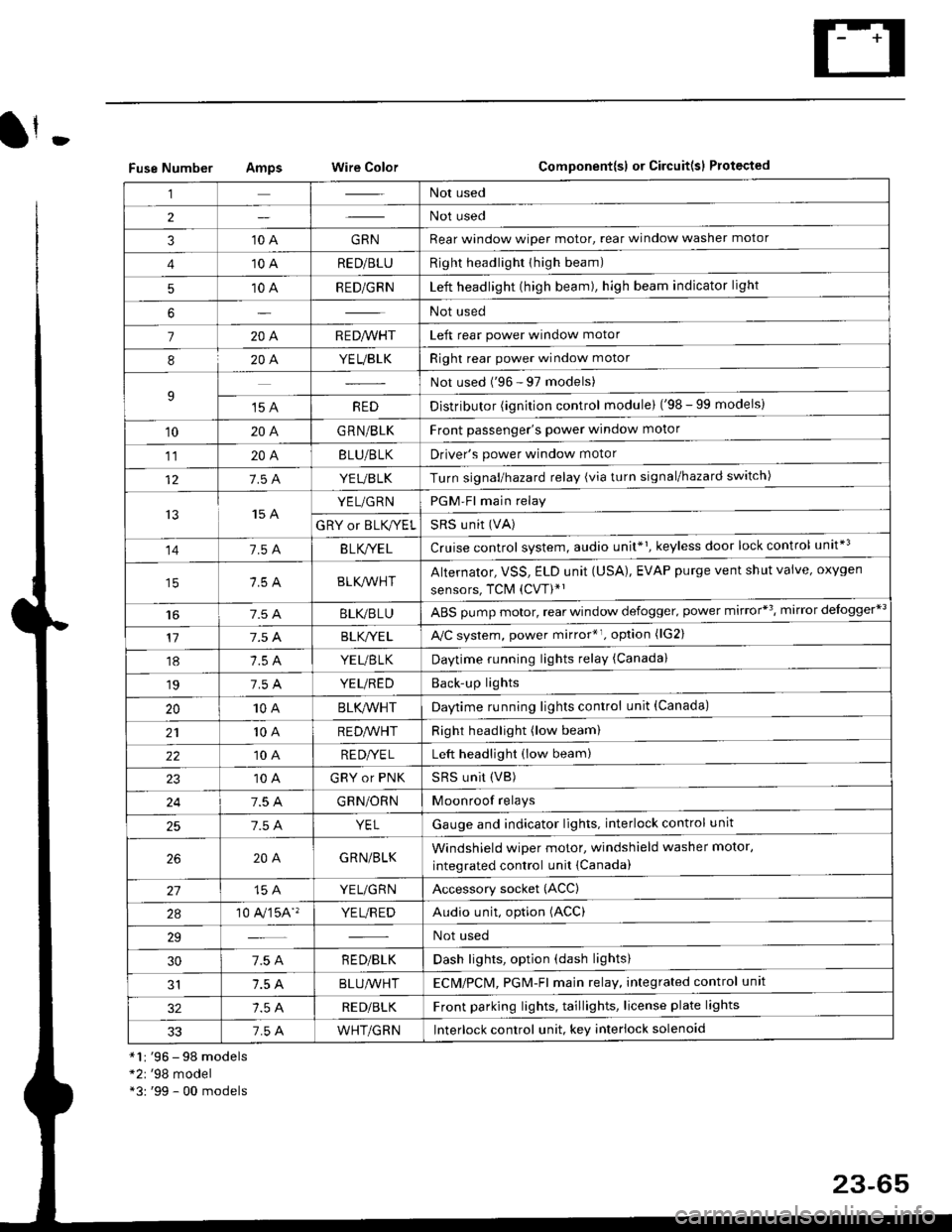
Fuse NumberAmpswire ColorComponent{sl or Circuit(sl Protected
*1r '96 - 98 models*2r '98 model*3: '99 - 00 models
,lNot used
2Not used
310 AGRNRear window wioer motor, rear window washer motor
410 ARED/BLURight headlighr thigh beam)
510 ARED/GRNLeft headlight (high beam), high beam indicator light
6Not used
7204R E D/VVHTLeft rear power window motor
820A.YEUBLKRight rear power window motor
9Not used ('96 - 97 models)
't5 AREDDistributor (ignition control module) ('98 - 99 models)
10204G RN/BLKFront passenger's power window motor
1120ABLU/BLKDriver's power window motor
127.5 AYEUBLKTurn signal/hazard relay (via turn signal/hazard switch)
t515 AYEL/GRNPGM-Fl main relay
GRY or BLK,^/ELSRS u nit (VA)
141.54B LK/YE LCruise control system, audio unit*1, keyless door lock control unit*3
BLK/lr'r'HTAlternator, VSS, ELD unit (USA), EVAP purge vent shut valve, oxygen
sensors, TCM (CVT)*'
t6BLI(,/BLUABS pump motor, rear window defogger. power mirror*3, mirror delogger*3
177.5 ABLK,/YE LA,/C system, power mirror*r. option (lG2)
18YEUBTKDaytime running lights relay (Canada)
197.5 AYEUREDBack'up lights
2010ABLK/VVHTDaytime running lights control unit (Canada)
2110 AREDA/VHTRight headlight (low beam)
2210 ARE DI/E LLeft headlight (low beam)
10 AGRY or PNKSRS UNit (VB)
247.5 AGRN/ORNMoonroof relays
257.5 AYELGauge and indicator lights. interlock control unit
204GRN/BLKWindshield wiper motor, windshield washer motor,
integrated control unit {Canada)
15 AYEL/GRNAccessory socket (ACC)
2a10 A,/'�]5A''YE L/R EDAudio unit, option (ACC)
29Not used
307.5 AR ED/BLKDash lights, option (dash lights)
1.5 ABLUA/VHTECM/PCl\4, PGM-Fl majn relay, integrated control unit
RED/BLKFront parking lights, taillights, license plate lights
337.5 AWHT/GRNlnterlock control unit. key interlock solenoid
23-65
Page 1546 of 2189
Ground Distribution
Circuit ldentification (conf dl
'9&98 models:
(t[oileas6)>{ BRN/BLKLGl II EcM/PcMlcz J
[..........{ BFNaLKCKF sensor jL .-!l 8LU/FED
Knoct s€rlsor (KS)r' ::{ REDtsLU
PimaryH02S*?- wHT
Matnsnafi g]€eo sdnsoa -'1 t I HEL)
Counlersiall speed sensor --={Fl BIU
Ecr#PcM ----Tal WHT/BED
Dive trjiley speed seftsor -1ll FED,ALU
0 ven pulley speed sensor .-lJ WHT
Seconftry gear shalt speed sansor .-!.1 WHT/RED
44:lil
ECIVPCM
)*"Dl6YBengine
Dl6Y5, D16Y7 sngine
vtl
8BM/BLK - IBBi1/BLK _ I^l^1ll'. I rcu rcwr
**' -i IWHT/RED + ]
El , Engln" *lr" h"rn""" - - - - - - : Shietorns
E : Main *re harness
23-76
* 1 :D16Y5,016Y8 engino* 2 : Excepl Dl 6Y5 engine (i//T)+3: D16Y5 engine (Mfi)
Page 1547 of 2189
rt
'99-00 models:
(5i%ease)E>4 BRNiBLK
i.,.,].',,-
ERNi BtK
BRIVBLK
BFN/BLK
BRN/BLK
BRN]BLK
BRIl/8LK
BFN/BLK
r * s r;l ao^r,qt r
CKF s€nsor 1t -1ll ELU/FEU
Knoq( sonsor (r15J '-l !l r{EUl6LU
P maryHo2s*?H wHT
Mainshafl speeo ssnsor -1ll fiEU
Coutershall sp€ed sensor -+F ] BLU) ..",r.u,.0n
016Y7, Dl6Y5 (CW) ongines
;;=-"r,i,-l
Ly"::::::::
I Secondary Ho2s :{ WHT/RED-;'4:v-..1
RED/BLU - I
wHT - f rau,rru (an )
pgTpse- J
*1i016Y5, Dl6Y8engines *4:016Y7, Bl6AzerEines lcont'd)*2: Excepl DI6YSengino ([VT) *5: D16Y5, D16Y7, D16Y8Bngines* 3:Dl6Y5 sngine ([VT) *6:B16M, D16Y8,016Y5 (CW)engines
015Y5 (LVT) sngine
41-.1
Dfiv6 prirEy speeo sonsot -1l l hEL,bLU
Driven gr ley sp€ed sensor -- F I WHT
Secondary gea sian sp€ed sensor .-ll WHT/RED
E : Engine w re harness E : Rear h€al6d orygen sensor sLlb harness
IIJ : Main wire harnsss ------ shielding
816A2, Dl6Ygengiftes
23-77
Page 1573 of 2189
lgnition System
-Circuit Diagram: '96 - 97 models
.i-
8LU
I
nBLU BLU I
tl
lnI TESTI TACHOMETEF\-7 CONNECTOR
TACHOMETERTCM (CW)
J-) {sh,eldinsr't I
tfYEL BBN/BLK
+l
I:
G101
$t+++
UNDER HOOD FUSE/ RELAY 8OX
BLh TEL YEL GBN
BLKlYEL
IAl
BLK/YEL YELIGFN
IGN]TIONCOL
TDCrTop dead cenlerCKP: Crankshall postionCYP Cylnder poslon
TDC]CKP]CYP SENSoR
" *]BLU'*2 WHI BLU
IGNITION CONIROLMODULE (CM)
/ Has b'r ll n\I iorse I
rUSE FE-AV BO}
*u r-. .-*---{<9ot # u,,."r. | |
\j/ El v
tl
23-103
Page 1598 of 2189
Gauge Assembly
Component Location Index
SRS components are located in this area. Review the SRS component locations, precautions, and procedures in the SRS
section (24) before performing repairs or service.
6x1.0mm9.8 N.m 11.0 kgf.m,22lbt.lrl
VEHICLE SPEED SENSOR {VSS)Troubleshooting, page 23-1 40
GAUGE ASSEMBLYGau ge/lndicator/TerminalLocation Index, page 23-129Removal, page 23-135Bulb Location, page 23-136Disassembly, page 23 138
PARKING BRAKE SWITCH
FLUIO LEVEL SW]TCH
23-128
ENGINE OIL PR€SSURE SWITCH
Page 1599 of 2189
JGau ge/lndicator/Terminal
With tachometer;
CONNECTOR "A"
{A/T GEAR POSITION INDICATOR}
Location lndex
CONNECTOR "8"
{GAUGE and INOICATOR)CONNECTOB "C"
CONNECTOR "D"
{ABS INDICATORI
SPEEDOMETER:Indicates 60 km/h at 637 rpm or
60 mph at 1,025 rpm o{thevehicle speed sensor (VSS).
A/T GEAR POSITIONINDICATORSee page 23 149
TACHOMETER:Indicates 100 rpm at200 pulses per minuteol the ignition controlmodule (lCMi.FUEL GAUGEENGINE COOLANT TEMPERATURE (ECT) GAUGE
(cont'd)
23-129
(GAUGE end INDICATORI
A1-----------+816
JlltlllulllllrL
c1 --------->c13
1ililil{ilrL
oooo o 0006^
)og @ @ o^o @ )'l |. o
Fl- - -> F5E1_ _ -->E5D1- --+05
oo/ \oo
Gauge/Sending Unit Test, page 23-142
Page 1600 of 2189
Gauge Assembly
Gauge/lndicator/Terminal Location Index (cont'd)
Without tachometer:
CONNECTOR "A"
IA/T GEAR POSITION INDICATORICONNECTOR "8"
{GAUGE and INDICATOR}CONNECTOR "C"
(GAUGE and INDICAIORI
CONNECTOR "F"
{SRS INDICATOR)CONNECTOR "D"
{ABS INDICATORI
SPEEDOMETER:Indicates 60 km/h at 637 rpm or60 mph at 1,025 rpm ofthevehicle speed sensor (VSS).
ENGINE COOLANT TEMPERATUFE (ECT) GAUGEA/T GEAR POSITIONINDICATOFSee page 23 149FUEL
A1 ------> 46
----> al4
B1. - --------------->B16
JilililHililil1
C1-- - --------..+C13
JililHililL
Oo_o-o O 0006
lus 0 0 Bu-. )
oo/ \oo
23-130
Gauge/Sending Unit Test, page 23 142
Page 1610 of 2189
Vehicle Speed Sensor (VSSI
Troubleshooting
Before testing, inspect the No. 15 (7.5 A) fuse in the under-dash fuse/relay box.
TEST HARNESSOTLAJ _ PT3O2OAREO TEST HARNESSCLIP
PROTECTIVETAPE
TEST HARNESSOTLA' . PT3O2OA
(To next page)
Test the BLK wire:1. Disconnect the 3P connectorfrom the vehicle speed sensor(vss).
2. Connect the test harness(07LAJ PT30200) only to theengine wire harness,3. Connect the RED test harnessclip to the positive probe of a
4. Check for continuity betweenthe RED test harness clip andbody ground.
Repair opon in the BLK wireb€twe€n the VSS and G101.ls there continuity?
Te3t the BLK/YEL wire:1. Connect the WHT test harnessclip to the positive probe of avoltmeter, and connectthe REDtest harness clip to the negativeprobe.2. Turn the ignition switch ON {ll).
Repair open in iho BLK/YEL wirebetween the VSS and the under-d6sh tuse/relav box.
vss
GRN TEST HARNESS
RED TEST HARNESS
WHT TEST HARNESS CLIP
23-140