Page 1135 of 2189
)
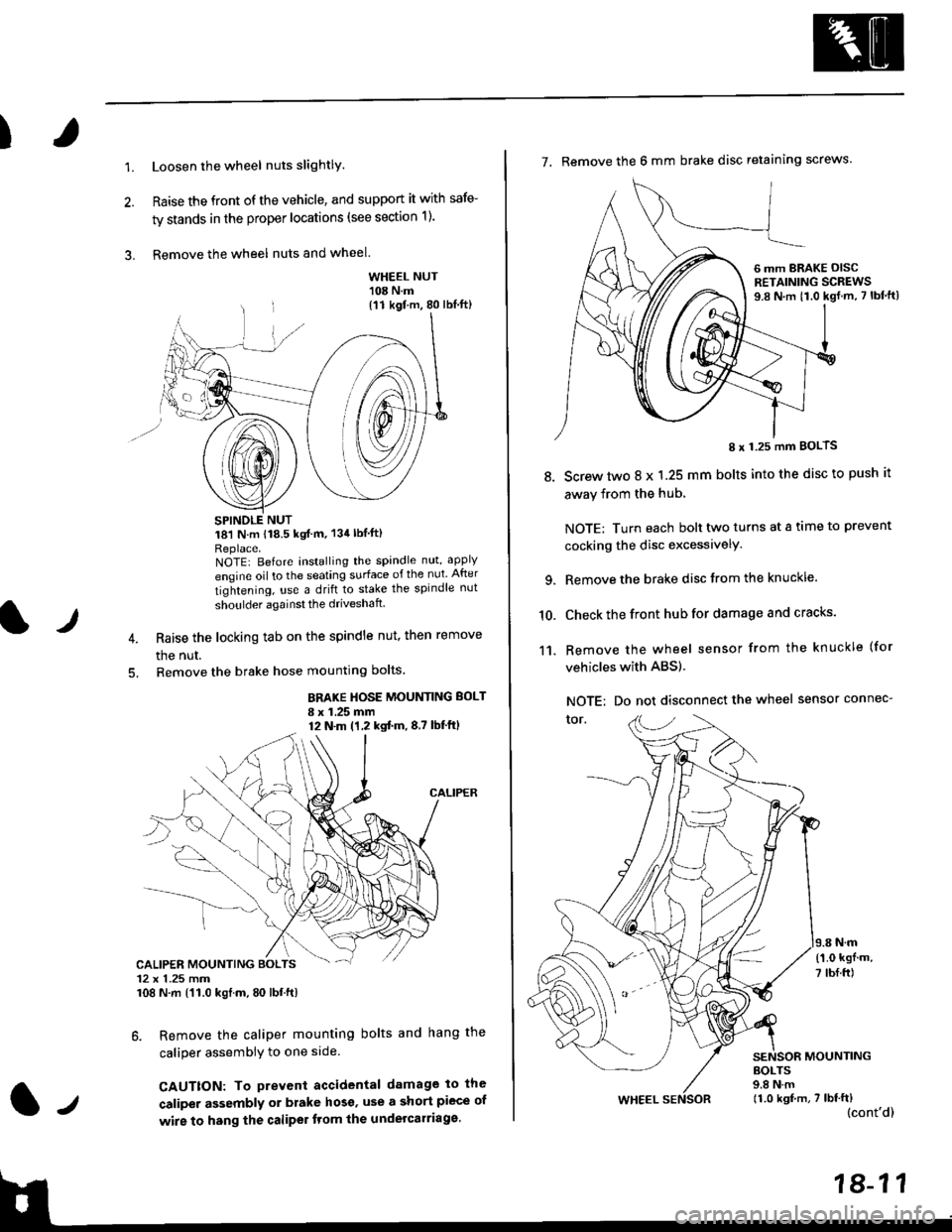
1.Loosen the wheel nuts slightlY.
Raise the front of the vehicle, and support it with safe-
ty stands in the proper locations (see section 1).
Remove the wheel nuts and wheel.3.
l)
WHEEL NUT'108 N.m
18'l N.m 118.5 kgf m, 134lblfti
Replace.NOTEI Before installing the spandle nut, apply
engine oil to the seating surface of the nut After
tightening, use a drift to stake the spindle nut
shoulder againsl the driveshaft
Raise the locking tab on the spindle nut, then remove
the nut.
Remove the brake hose mounting bolts.
BRAKE HOSE MOUNTING BOLT
I x 1.25 mm12 N.m (1,2 kgtm,8,7 lbf'ftl
6. Remove the caliper mounting bolts and hang the
caliper assembiy to one side
CAUTTON: To prevent accidental damage to the
caliper assembly or brake hoso' use a short piece of
wire to hang the caliPer tlom lhe undelcarriage.
{11 kgf m, 80 lbl.ft)
CALIPER MOUNTING BOLTS12 x 1.25 mm108 N.m {'11.0 kgtm, 80 lbt.ft)
7. Remove the 6 mm brake disc retaining screws.
8.
I x 1.25 mm BOLTS
Screw two 8 x 1.25 mm bolts into the disc to push it
away from the hub,
NOTE: Turn each bolt two turns at a tame to prevent
cocking the disc excessivelY.
Remove the brake disc from the knuckle.
Check the front hub for damage and cracks.
Remove the wheel sensor from the knuckle (for
vehicles with ABS).
NOTE: Do not disconnect the wheel sensor connec-
tor.
N.m
6 mm BRAKE OISCRETAINING SCREWS9.8 N.m t1.0 kgf.m, 7 lbf'ft)
{'1.0 kgf m,
7 tbf.ft)
10.
11.
MOUNTING
WHEEL
BOLTS9.8 N.m11.0 kgf,m, 7 lbf'ft)(cont'd)
Page 1139 of 2189
I
NOTE: Wash the knuckle and hub thoroughly in
high flash point solvent before reassembly.
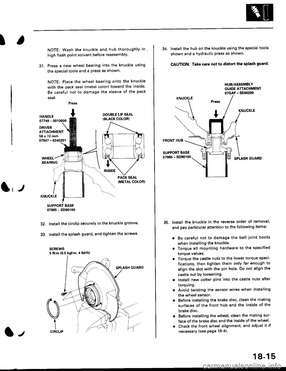
31. Press a new wheel bearing into the knuckle using
the specialtools and a press as shown
NOTE: Place the wheel bearing onto the knuckle
with the pack seal (metal color) toward the inside
Be careful not to damage the sleeve of the pack
seal.
Press
HANOI.E07749 - 001
DRIVERATTACHMENT58x72mm07947 - 6340201
DOUBLE LIP SEAL
{BLACK COLOR)
KNUCKLE
SUPPORT BASE07965 - SD90100
Installthe circlip securely in the knuckle groove'
Installthe splash guard, and tighten the screws.
scREws5 N.m (0.5 kgd m, 4lbt'ft)
32.
33.
l-,
18-15
34. lnstall the hub on the knuckle using the specialtools
shown and a hydraulic press as shown.
CAUTION: Take care not to distort tho splash gusrd'
HUB/ASSEMBLYGUIDE ATTACHMENT07GAF- SEflt2d)
KNUCKLE
FRONT HUB
SUPPORT BASE
07966 - StXx)100SPLASH GUARD
tnstall the knuckle in the reverse order of removal'
and pay particular attention to the following items:
. Be careful not to damage the ball joint boots
when installing the knuckle.
. Torque all mounting hardware to the specified
torque valugs.
. Torque the castls nuts to the low€r torque specl-
fications, then tighten them only far enough to
align the slot with the pin hole. Do not align the
castle nut by loosening.
. lnstall new cotter pins into the castle nuts after
torquing.
. Avoid twistin0 the sensor wires when installing
the wheel ssnsor.
. Before installing the brake disc, clean the mating
surfaces of the front hub and the inside of the
brake disc.
. Before installing the wheel, clean the mating sur-
face ofthe brake disc and the inside of the wheel
. Check the front wheel alignment, and adjust it if
necessary (see page 18-4).
Page 1140 of 2189
Front Suspension
L
Lower Ball Joint Replacement
Remove the knuckle (see page 18-11).
Remove the boot by prying the set ring off.
Check the boot for deterioration and damage.
replace if necessary.
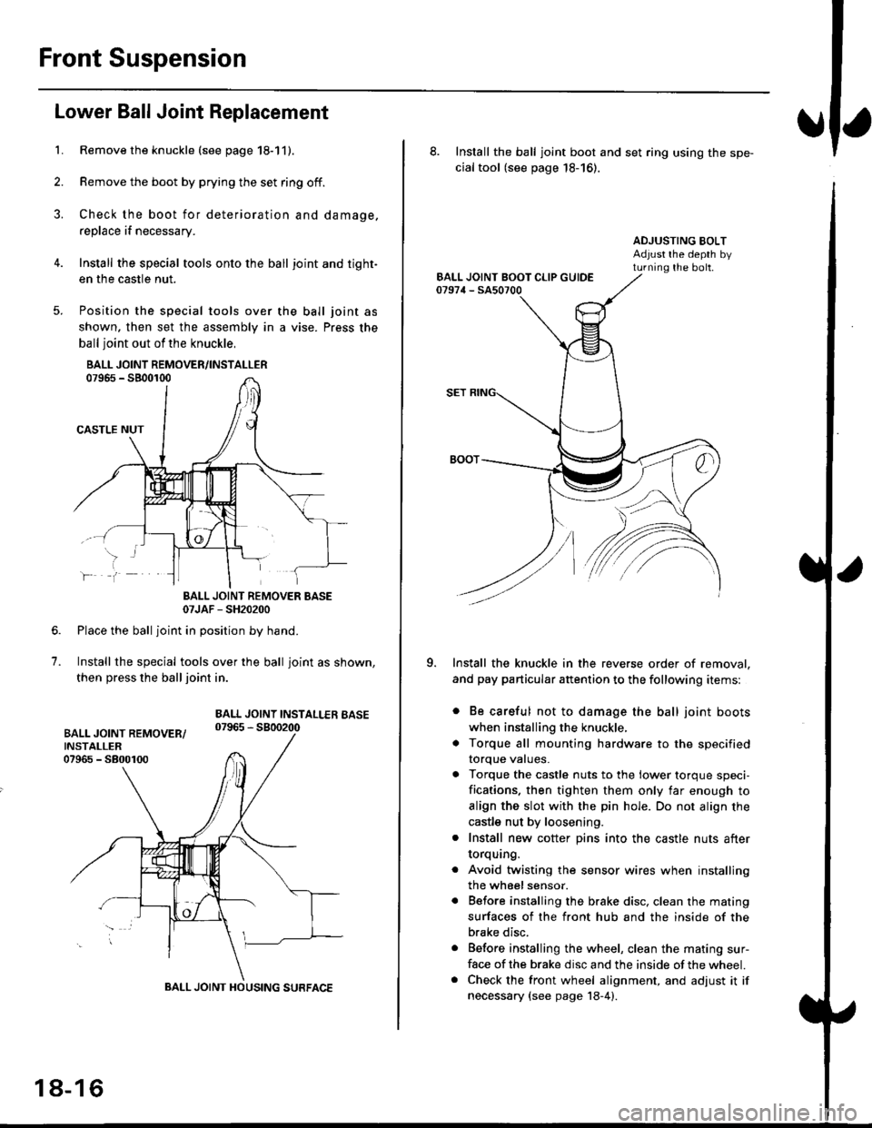
Install the special tools onto the ball joint and tight-
en the casfle nut.
Position the special tools over
shown. then set the assembly in
ball joint out of the knuckle,
BALL JOINT REMOVER/INSTALLER07965 - SB00r00
CASTLE NUT
the ball joint as
a vise. Press the
lf
7.
BALL JOINT REMOVER BASE07JAF - SH20200
Place the ball joint in position by hand.
Install the special tools over the ball joint as shown,
then press the ball joint in.
BALL JOINT INSTALLEB BASE07965 - 5800200
BALL JOINT HOUSING SURFACE
18-16
8. Install the ball joint boot and set ring using the spe-
cial tool (see page 18-16).
ADJUSTING BOLTAdjust rhe depth byturning the bolt.
Install the knuckle in the reverse order of removal,
and pay particular attention to the following items:
. Be careful not to damage the ball joint boots
when installing the knuckle,
. Torque all mounting hardware to the specified
torque values.
. Torque the castle nuts to the lower torque speci-
fications. then tighten them only far enough to
align the slot with the pin hole. Do not align the
castle nut by loosening.
. Install new cotter pins into the castle nuts after
torquang.
. Avoid twisting the sensor wires when installing
the wheel sensor.
. Before installing the brake disc. clean the mating
surfaces of the front hub and the inside of the
brake disc.
. Before installing the wheel, clean the mating sur-
face of the brake disc and the inside of the wheel.. Check the front wheel alignment, and adjust it if
necessary {see page 18-4).
Page 1196 of 2189
L-
t
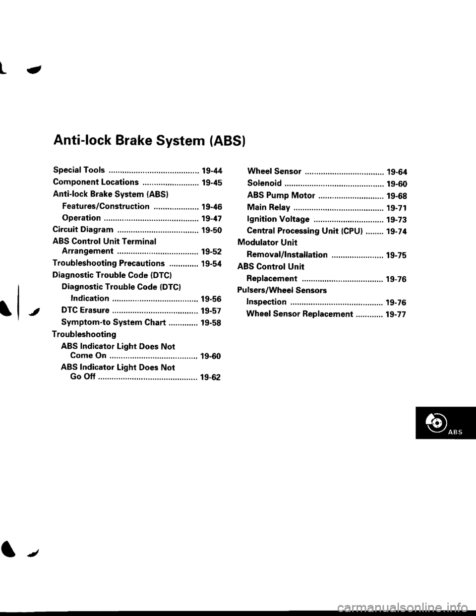
Anti-lock Brake System (ABSI
Special Tools ............. 19-44
Component Locations ......................... 19-45
Anti-lock Brake System (ABS)
Features/Construction ..................., 19-46
Operation ............... 19-47
Circuit Diagram ......... 19-50
ABS Control Unit Terminal
Arrangement ......... 19-52
Troubleshooting Precautions ............. 19-54
Diagnostic Trouble Code (DTCI
Diagnostic Trouble Gode (DTCI
Indication ........... 19-56
DTC Erasure ........... 19-57
Symptom-to System Chart ............. 19-58
Troubleshooting
ABS Indicator Light Does Not
Come On ............ 19-60
ABS Indicator Light Does Not
Go Off ............................................ 19-62
Wheel Sensor ........ 19-64
Solenoid ................. 19-60
ABS Pump Motor ............................. 19-68
Main Relay ............. 19-71
lgnition Voltage .... 19-73
Central Processing Unit {CPU} ........ 19-74
Modulator Unit
Removal/lnstallation ....................... 19-75
ABS Control Unit
Replacement ......... 19-76
Pulsers/Wheel Sensors
Inspection .............. 19-76
Wheel Sensor Replacement ............ 19-77
t/
Page 1198 of 2189
Component Locations
ta
SERVICE CHECK CONNECTOR {2PIBIGHT.REAR WHEELSENSOR CONNECTORMOOULATOR UNITABS CONTROL UNIT
RIGHT-REAR WHEEL SENSOR
LEFT.R€AR WHEELSENSOR CONNECTOR
J
UNDER.DASH FUSE/RELAY 8OX
LEFT.FRONT WHEEL SENSOR
ABS +B (20 A) FUSE
UNDER.HOOD FUSE/RELAY BOX
lcl lilo Al FUSE
ABS INDICATOR LIGHT
UNOEF.DASI{ FUSE/RELAY BOX
HORN/STOP I15 A) FUSE
UNDER.HOOO ABS FUSE/RELAY BOX
PUMP MOTOR {'O A} FUSE
PUMP MOTOR BELAY
E
o
METEB I7.5 AI FUSE
0
0
0
00000 n
00000 u
BR DEF RLY 17,5 A) FUSE
t
MTR CHECK (7.5 AI FUSE
19-45
Page 1200 of 2189
t-Operation
t
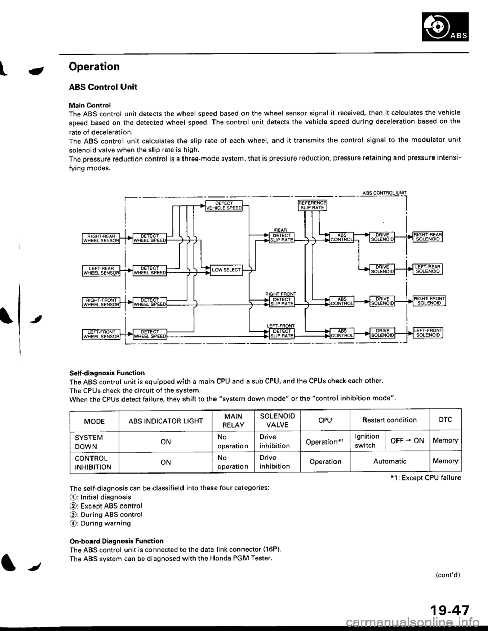
ABS Control Unit
Main Control
The ABS control unit detects the wheel speed based on the wheel sensor signal it received, then it calculates the vehicle
speed based on the detected wheel speed. The control unit detects the vehicle speed during deceleration based on the
rate of deceleration.
The ABS control unit calculates the slip rate of each wheel. and it transmits the control signal to the modulator unit
solenoid valve when the slip rate is high.
The pressure reduction control is a three-mode system, that is pressure reduction, pressure retaining and pressure intensi-
fying modes.
Self -diagnosis Funqtion
The ABS control unit is equipped with a main CPU and a sub CPU, and the CPUS check each other'
The CPUs check the circuit of the svstem.
When the CPUS detect failure, they shift to the "system down mode" or the "control inhibition mode"
The self-diagnosis can be classifield into these four categories:
O: Initial diagnosis
@: Except ABS control
@: During ABS control
@: During warning
On-board Diagnosis Funstion
The ABS control unit is connected to the data link connector {16P).
The ABS system can be diagnosed with the Honda PGM Tester.
(cont'd)
MODEABS INDICATOR LIGHTMAIN
RELAY
SOLENOID
VALVECPURestart conditionDTC
SYSTE IV
DOWNONNo
operation
Drive
inhibitionOperation*rlgnition
switchOFF + ONMemory
CONTROL
INHIBITIONONNo
operalron
Drive
inhibitionOperationAutomaticMemory
*1: Except CPU failure
/
19-47
Page 1202 of 2189
L
Wheel Soeed and Modulator Contlo
t
OUTLETVALVE ON
OFF
INLETVALVE ON
OFF
t\,40ToR
ON
OFF
when the wheel speed drops sharply below the vehicle speed, the inlet valve closes to retain the caliper fluid pressure
When the wheel speed drops further, the outlet valve opens momentarily to reduce the caliper fluid pressure. The pump
motor starts at this time.
As the wheel speed is restored, the inlet valve opens momentarily to increase the caliper fluid pressure.
Wheel SensoJ
The wheel sensors are the magnetic contactless type
As the gear pulser teeth rotate past the wheel sensor's magnetic coil, AC current is generated The AC frequency changes
in accordance with the wheel speed. The ABS control unit detects the wheel sensor signal frequency and thereby detects
the wheel speed.
There are four wheel sensors, one for each wheel
The gear pulser has 50 teeth.
EEL SPEED
at LOW SPEEDgl
=o
GEAR PULSEBWHEEL SENSOBat HIGH SPEED
/
19-49
Page 1204 of 2189
tABS CONIROL UN]TECM / PCMISCS'
V
,,, +-{l-, ?,,] B6li! [,b.,,,,,-F-
SENSOR
+B
YWHTNED
8U(
J-
G,Ol, Ga02
l
\EWIK
LEFT.
RIGHT,
LEFT
;___.|-1
**1. ,I
coierou
SERVICE CHECKCONNECTOR (2P}
lrl2f
OATA LINKCONNECTOR O 6P)
WHEEL SENSOR2P CONNECTOB
FRONT
/.[Ttl\
REAR
tc-T-lI zlr[B'1213
ABS CONTROL UNIT 26P CONNECTOR1O numb€r)
12346/8Il0./ tt12r3
14 t516 1719 ,/2123
-o&"^1'
cot, croz
Terminalside ofmale terminals
ABS CONTROL UNIT 22P CONNECTOR1! numb€r)
/Wire side of female terminals
19-51