Page 791 of 2189

Road Test
NOTE: Warm up the engine to normal operating tem peratu re (the rad iator fan comes on )'
1. Apply parking brake and block the wheels. Start the engine, then shift to E position while depressing the brake
Dedal, Depress the accelerator pedal and release it suddenly. The engine should not stall'
2. Repeat same test in E Position.
3. Test-drive the vehicle on a flat road in the E position. Check that the shift points occur at approximate speeds shown
in the table. Also check for abnormal noise and clutch slippage.
NOTE: Throttle position sensor voltage represents the throttle opening
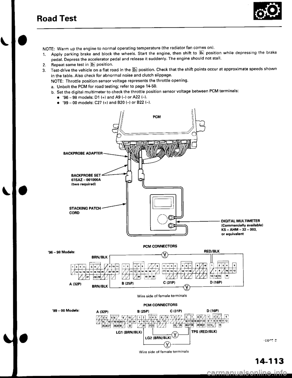
a. Unbolt the PCM for road testing; refer to page 14-50.
b. Setthedigital multimeter to check the th rottle position sensor voltage between PCM terminals;
. '96 - 98 models: D1 {+) and A9 (-) or 422 (-}.
. '99 - 00 models: C27 (+) andB20t-) orB22{-}.
BACKPROBE ADAPTER
BACKPROBE SET07sAz - 001oq)A{two requiredl
DIGIIAL MULTIMETERlCommercially available)KS-AHM-32-003,or equivalenl
'96 - 98 Modelsr
Wire side ol temale terminals
PCM CONNECTORS
B t25Pl c (31P)
LG1 IBRN/BLK)
I (25P1c (31P}
A t32PtD (16P)
Wire side ol female terminals
'9!t - 00 Models:
1+113
Page 800 of 2189
Transmission
Removal
@Maks sure lifts, iacks and safety stands are placedproperly, and hoist bracket ate aftached to the cor_rec{ position on the engine lsee section 1).Apply parking brake and block rear whoels so vehiclewill not roll off stands and fall on you while workingunder it.
CAUTION: Use tender covers to avoid damaging paint-ed surfaces.
1, Disconnect the battery negative (_) terminal fromthe battery, then remove the positive (+) terminal.
2. Remove the intake air duct.
D16Y7 engins:
Remove the intake air duct and resonator.
D16Y8 engine:
Remove the intake air duct and the air cleaner hous-ing assembly,
3. Remove the starter cables and cable holder fromthe starter motor.
MOTOR CABLE
MOTOR CABLE
14-122
4. Remove the transmission ground cable, and discon_nect the lock-up control solenoid connector.
LOCK.UP CONTROLSOLENOID CONNECTOR
5, Disconnect the vehicle speed sensor (VSS) connec_tor and the countershaft speed sensor connector.
VEHICLE SPEED
Page 801 of 2189
6. Remove the transmission housing mounting bolts
and the rear engine mounting bolt.
Disconnect the shift control solenoid, the linear sole-
noid, and the mainshaft speed sensor connectors'7.
SHIFT CONTROLSOLENOID CONNECTORLINEAR SOLENOIDCONNECTOR
MOUNTING BOLTS
BRACKET
8. Remove the drain plug, and drain the automatic
transmission fluid (ATF). Reinstall the drain plug
with a new sealing washer.
DRAIN PLUG18 x 1.5 mm'9 N m t5 o kgf'm' 36 lbf'ft|
9. Remove the splash shield.
Replace.
SPLASH SHIELD
{cont'd)
14-123
Page 807 of 2189

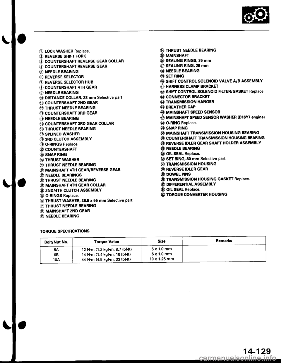
O LocK WASHER Replace,
O REVERSE SHIFT FORK
O COUNTERSHAFT REVERSE GEAR COLLAR
G) COUNTERSHAFT REVERSE GEAR
@ NEEDLE BEARING
@ REVERSE SELECTOR
O REVERSE SELECTOR HUB
@ COUNTERSHAFT 4TH GEAR
O NEEDLE BEARING
@ DISTANCE GOLLAR, 28 mm Selective part
O COUNTERSHAFT 2ND GEAR
@ THRUST NEEDIE BEARING
@ COUNTERSHAFT 3RD GEAR
@ NEEDLE BEARING
@ COUNTEBSHAFT 3RD GEAR COLLAR
@ THRUST NEEDLE BEAFING
O SPLINED WASHER
@ 3RD CLUTCH ASSEMBLY
@ O-RtNGs Replace.
@ COUNTERSHAFT
@ SNAP RING
@ THRUST WASHER
€) THRUST NEEDTE BEARING
@} MATNSHAFT 4TH GEAR/REVERSE GEAR
@i NEEDLE BEARINGS
@ THRUST NEEDLE EEARING
@) MAINSHAFT 4TH GEAR COLLAR
@ 2ND/4TH CLUTCH ASSEMBLY
@ o-RlNGs Replace.
@ THRUST WASHER,36.5 x 55 mm Sel€ctive part
@ THRUST NEEDLE BEARING
@ MAINSHAFT zND GEAR
@ NEEDLE BEARING
@ THRUST NEEDLE BEARING
@ MAINSHAFI
@ S€ALING RINGS, 35 mm
@ SEALING RING,29 mm
@} NEEDIE BEARING
@ SET RING
@ sHrFT CONTROL SOLENOID VALVE A/B ASSEMSLY
@ HARNESS CLAMP BRACKET
@ SHIFT COI,ITROL SOI"ENOID FILTER/GASKET Replace.
@ CONNECTOR BFACKET
@D TNANSMISSION HANGER
@ BREATHER CAP
@ MAINSHAFT SPEED SENSOR
@ MATNSHAFT SPEED SENSOR WASHER {Dl6Y' ongine}
@ O-RING Replace.
@ SNAP RING
@ MAINSHAFT TRANSMISSION HOUSING BEARING
@ OOUNIERSHAFT TRANSMISSION HOUSING BEARING
@ REVERSE IDLER GEAR SHAFT HOLDER ASSEMBLY
@ NEEDI.E BEARING
@ olL SEAL Replace.
@ SET RING, fll mm Selective part
@ rnANsMrssloN HouslNG
@ REVERSE IDI."ER GEAR
@ DowEL PINS
@ TRANSMISSION HOUSING GASKET Replace.
@ DIFFERENfIAL ASSEMBLY
@ OIL SEAL Replace.
@ TOROUE CONVERTER HOUSING
TOROUE SPECIFICANONS
Boh/Nut No.Torquo valueSizeRomarks
6B
10A
12 N.m {1.2 kgf.m,8.7 lbf.ft)
14 N.m (1.4 kgf'm, 10lbf'ft)
44 N.m (4.5 kgf.m, 33 lbf'ft)
6x1.0mm
6x1.0mm
10 x 1.25 mm
14-129
Page 809 of 2189

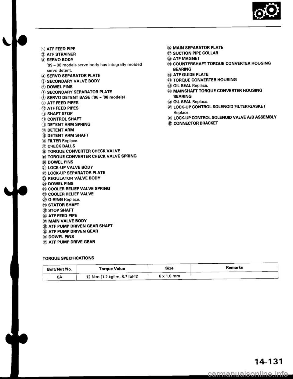
O ATF FEED PIPE
O ATF STRAINER
O SERVO BODY'99 - 00 models servo body has integrally molded
servo detent.
@ SERVO SEPARATOR PLATE
(' SECONDARY VALVE BODY
@ DOWEL P|NS
O SECONDARY SEPARATOR PLATE
@ SERVO DETENT BASE ('�96 -'98 models)
O ATF FEED PIPES
(D ATF FEED PIPES
O SHAFT STOP
@ CONTROL SHAFT
€D DETENT ARM SPRING
@ DETENT ARM
(9 DETENT ARM SHAFT
@ FILTER Replace.
(? CHECK BALLS
@ TOROUE CONVERTER CHECK VALVE
@ TOROUE CONVERTER CHECK VALVE SPRING
@ DOWEL PINS
@ LOCK.UP VALVE BODY
@ LOCK-UP SEPARATOR PLATE
@ REGULATOR VALVE BODY
@} DOWEL PINS
@ COOLER RELIEF VALVE SPRING
@ COOLER RELIEF VALVE
@ O-RING Replace.
@ STATOR SHAFT
@ STOP SHAFT
@ ATF FEED PIPE
@ MAIN VALVE BODY
@ ATF PUMP DRIVEN GEAR SHAFT
@ ATF PUMP DRIVEN GEAR
@ DOWEL PINS
65) ATF PUMP DRIVE GEAR
@ MAIN SEPARATOR PLATE
@ SUCTION PIPE COLLAR
@ ATF MAGNET
@ COUNTERSHAFT TOROUE CONVERTER HOUSING
BEARING
@ ATF GUIDE PLATE
@ ToRoUE CONVERTER HOUSING
@ OIL SEAL Replace.
@ MAINSHAFT TOROUE CONVERTER HOUSING
BEARING
@) olL SEAL Replace.
@ LOCK-UP CONTROL SOLENOID FILTER/GASKET
Reolace.
@ LOCK-UP CONIROL SOLENOID VALVE A/B ASSEMELY
@ CONNECTOR BRACKET
TOROUE SPECIFICANONS
Bolt/Nut No.Torque ValugSiz€Remarkg
12 N.m (1.2 kgf.m,8.7 lbnft)6x1,0mm
14-131
Page 863 of 2189

16. Install a new set ring on the end of each driveshaft'
17. Installthe right and left driveshafts (see ssction 16)
CAUTION: Whil6 installing the driveshafE in the
diffarential, be surs not lo allow du3t and othor for-
eign particl€s to enler into the transmission.
NOTE:
. Clean the areas where the driveshafts contact the
transmission (differential) thoroughly with sol-
vent or carburetor cleaner, and dry with com-
pressed air.
. Turn the right and left steering knuckle fully out-
ward, and slide each driveshaft into the differen-
tial until you feel its set ring clip engage the side
gear.
18. Install the damper fork, then install the rightand left
ball joints to the each lower arm with the castle nuts
and new cotter Plns.
DAMPER PINCH BOLT
10 x 1 .25 mma3 N.m l4.ia kgf.m,
32 tbl.ftl
4l
COTTERReplace.SELF.LOCKING NUT
12 x 1.25 mm
6il N.m t6.5 kgf'm, il7 lbf ftl
Replace.
19. Install the splash shield.
{5.0 - 6.0 kgf m, 36 - iB lbf'ft|
CASTLE NUT12 x 1,25 mm49 - 59 N.m
20. Connect the mainshaft speed sensor, the linear sole-
noid and the shift control solenoid connectors.
SHIFT CONTROL SOLENOIO LINEAR SOITNO|o
CONNECTOR CONNECTOR
6 r 1.0 mrn12 N.m (1.219f.m,
E.7 lbf.frl
CONNECTOR
21. Connect the countershaft speed sensor and the vehi-
cle speed sensor (VSS) connectors.
VEHICI..E SPEED
SENSOR CONNECTOR
COUNTERSHAFTSPEED SENSORCONNECTOR
(cont'dl
14-185
Page 864 of 2189

Transmission
Installation {cont'd)
Connect the lock-up control solenoid connector. andinstall the transmission ground cable.
6 x '1.0 mm12 N.m {1.2 kgf.m, 8.7 lbl.ft}
LOCK.UP CONTROLSOLENOID CONNECTOR
Connect the staner cables on the staner motor. andinstall the cable holder.
NOTE; When installing the starter cable terminal.make sure that the crimped side of the ring terminalis facing out (see section 23).
6x1.0mm12 N.m 11.2 kg{.m.8.7 tbtftl
{0.9 kg'f.m, 7 lbf.ftl
TRANSMISSIONGROUND CABLE
b
14-186
STARTER CAELE
24. Installthe intake air duct.
D16Y7 engine:
Install the intake air duct and the resonaror.
D16Y8 engine:
lnstall the intake air duct and the air cleaner hous_ang assembly.
25. Refill the transmission with ATF (see page 14_1.18).
26. Connect the positive (+) cable first. then the nega-tive (-) cable to the battery.
27. Check the ignition timing (see section 23).
28. Start the engine. Set the parking brake, and shift thetransmission through all gears. three times. Checkthe shift cable adjustment (see page 14_190).
29, Check the front wheel alignment (see section 1g).
30. Let the engine reach operating temperature (thecooling fan comes on) with the transmission in Nor @ position, then turn it off and check the fluidlevel (see page 14- 7).
31. Road test as described on pages 14-113 thru ,14_116.
Page 872 of 2189

Special Tools
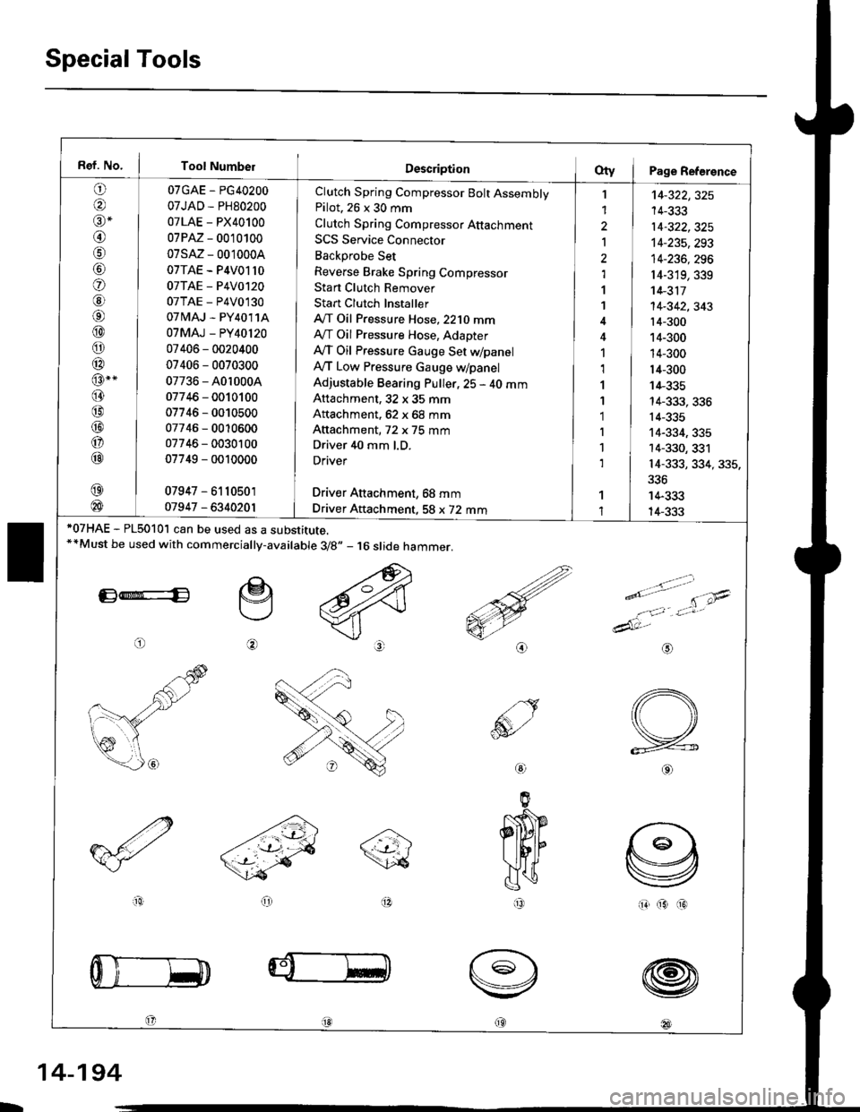
Ref. No. I Tool Number
o
@alr *
@
o
@6l
@
o
@
@-"
@
@
@
o
@
07GAE - PG40200
07JAD - PH80200
07LAE - PX40100
07PM - 0010100
07sM- 0010004
07TAE - P4V01l0
07TAE - P4V0120
07TAE - P4V0130
07 tvlAJ - PY4011A
07MAJ - PY40l20
07406 - 0020400
07406 - 0070300
07736 - A0r 0004
07746 - 0010100
07746 - 0010500
07746 - 0010600
07746 - 0030100
07749 - 0010000
07947 - 6110501
01947 - 6340201
Clutch Spring Compressor Bolt AssemblyPilot. 26 x 30 mm
Clutch Spring Compressor Attachment
SCS Service Connector
Backprobe Set
Reverse Brake Spring Compressor
Stan Clutch Remover
Stan Clutch Installer
A/T Oil Pressure Hose,2210 mmAy'T Oil Pressure Hose, Adapter
Ay'T Oil Pressure cauge Set WpanelAy'T Low Pressure Gauge w/panel
Adjustable Bearing Puller, 25 - 40 mmAttachment, 32 x 35 mm
Attachment, 62 x 68 mm
Attachment, 72 x 75 mm
Driver 40 mm l.D.
Driver
Driver Aftachment, 68 mm
Driver Attachment, 58 x 72 mm
I
1
2
Ia,l
1
1
1,1
1
1'1
I
1
1
't4-322,325
14-333
14-322,325't4-235,293
14-236, 296
r4-319,339't 4-311
14-342,343't4-300
14-300
14-300
14-300
14-335
14-333, 336
14-335
14-334, 335
14-330, 331
14-333, 334, 335,
336
14-333
14-333*07HAE - PL5010l can be used as a substitute.**Must be used with commercially-available 3/8.,- 16 slide hammer.
E*E
o
e
@
>.'.- -t-'- t'\;4
e'o
1:,'Jt*
dAt:-
io(313
@
@
@
@18l
aio
@
IR
L
14-194