Page 653 of 2189

Reassembly
CAUTION:
. Press the 3rd/4th and the 5th synchro hubs on the
mainshaft without lubrication.
o When installing the 3rd/,lth and the sth synchro
hubs, support the mainshaft on steel blocks, and
installthe synchro hubs using a prsss.
. Install the 3rd/4th and the sth synchro hubs with a
maximum plessur€ of 19.6 kN (2,000 kg, 14,466 lbl.
NOTE: Refer to page 13-67 for reassembly sequence.
1, Support 2nd gear on steel blocks, then install the
3rd/4th synchro hub using the special tools and a
press, as snown.
NOTE:
. After installing. check the operation of the
3rd/4th synchro sleeve and hub.
. Assemble the 3rd/4th synchro hub and sleeve
together betore installing them on the mainshaft.
Closed end
3RD/4THSYNCHRO HU3DBIVER, 10 mm l.O.07746 - 00301U)
/ lrrlcHlileNr. ss .- t.o.07746 - 0030,100
l.
3RD/{THSYNCHROSLEEVE
2ND GEAR
2. Install the sth synchro hub using the special tools
and a press as snown.
DRIVER, {0 mm l.O.07746 - 0030100
ATTACHMENT,35 mm LD.
sTH SYNCHRO HUB
07716 - 0030,100
3. Install the angular ball bearing using the special
tools and a press as shown.
PRESS
+
DRIVER, 40 mm LD.0?7a6 - It030100
Page 654 of 2189
Gountershaft Assembly
Index
DAMPER
ST GEARInspection, page 13-75
EALL EEARING
and operation.
NEEDLE BEARINGlnspect for wearano operaton.
5TH GEAR
4TH GEAR
3RD GEAR
NOTE:
3
The 4th and sth gears are installed with a press.
Prior to reassembling, clean all the parts in solvent, dry them and apply lubricant to any contact surfaces. The 4thand 5th gears. however, should be installed with a press before lubricating them.
REVERSE GEAR
LOCKNUT Replace108"0-108N.m
i11.0 - 0- l1.0kgtm,180-0-80lbttr
WASHER
DISTANCECOLLAR
COUNTERSHAFTInspection, page 13-77
NEEDLE BEARING
and operatron,
Inspection, page 13-75
NEEDLE BEARING
ano operatron,
SPACER
FRICTION DAMPER
DOUBLE CONE
Inspection, page 13 81
SYNCHRO SPRING
13-74
Page 658 of 2189

Gountershaft Assembly
Reassembly
CAUTION:
. Pross 4th and sth gears on the countershaft without
lubrication.
. When installing ilth and sth geafs, support the shaft
on steel blocks, and install the gears using a press.
. Install ilth and sth gear with a maximum pressure of
25.5 kN (2,600 ksf, 18,806lbf).
NOTE; Refer to page 13-74 for reassembly sequence.
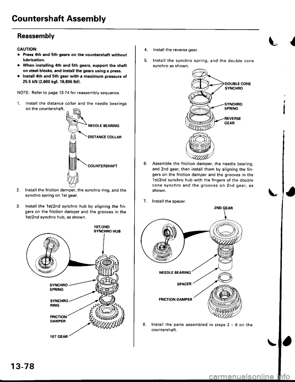
'1. Install the distance collar and the needle bearinos
on the countershaft.
COUNTERSHAFT
Install the friction damper, the synchro ring, and the
synchro spring on 1st gear.
Install the 1sv2nd synchro hub by aligning the fin-
gers on the friction damper and the grooves in the
1sv2nd synchro hub, as shown.
lST/2NO
13-78
lSI GEAR
insteps2-6onthe
{
4.lnstall the reverse gear.
Install the synchro spring. and the double cone
synchro as shown.
Assemble the friction damper, the needle bearing,
and 2nd gear, then install them by aligning the fin-gers on the friction damper and the grooves in the
1sv2nd synchro hub with the fingers of the double
cone synchro and the grooves on 2nd gear, as
snown.
Installthe spacer.
FRICTION DAMPER
Install the parts assembled
countershaft.
;
2ND GEAR
Page 662 of 2189
Differential
Index
FINAL DRIVEN GEARInspect tor wear and damage.
80 mm SHIMSelection, page'13,84
101 N.m {10.3 kgtm,74.5 lbf.ft)Left-hand threadsBALL BEAFINGInspect foa wear and ooeration.
13-82
Backlash Inspection
1. Place the differential assembly on V-blocks and installboth axles.
Measure the backlash of both pinion gears. lf thebacklash is not within the standard, replace the dif,ferential carrier.
Standard (New): 0.05 - 0.15 mm (0.002 - 0.006 inl
DIAL INDICATOR
Page 664 of 2189
Differential
Thrust Shim Adjustment
1. Install the differential assembly, making sure it bot
toms in the clutch housing, using the special tool as
shown.
ORIVER, 40 mm LO.o7746-0030100
lnstall the 80 mm shim.
NOTE: lnstall the 80 mm shim that was removed.
mm SHIM
13-84
(
4.
Install the transmission housing (see page 13-94).
NOTE: Do not apply liquid gasket to the mating sur-
face of the clutch housing.
Tighten the transmission housing attaching bolts(see page 13-94).
I x 1.25 mm
27 N'm (2.8 kgf.m, 20 lbf.ftl
Use the special tool to bottom the differential assem.
bly in the clutch housing.
Measure clearance between the 80 mm shim and
bearing outer race in the transmission housing.
Page 692 of 2189

Description
Electronic Control System (cont'd)
Shift Control
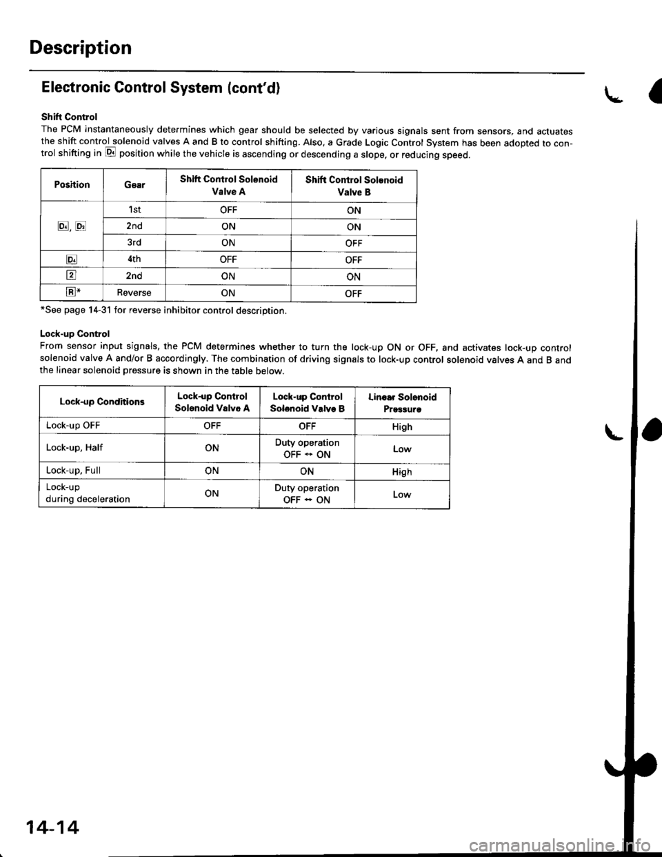
The PCM instantaneously determines which gear should be selected by various signals sent from sensors, and actuatesthe shift control solenoid valves A and B to control shifting. Also. a Grade Logic Control System has been adopted to con-trol shifting in E position while the vehicle is ascending or descending a slope, or reducing speed.
PoshionGearShift Control Solenoid
Vslve A
Shift Control Solenoid
Valve B
8,tr
1stOFFON
2ndONON
3rdONOFF
E4thOFFOFF
tr2ndONON
E-ReverseONOFF
*See page 14-31 for reverse inhibitor control description.
Lock-up Control
From sensor input signals, the PCM determines whether to turn the lock-up ON or OFF, and activates lock-up controlsolenoid valve A and/or B accordingly. The combination of driving signals to lock-up control solenoid valves A and B andthe linear solenoid pressure is shown in the table below.
Lock-up ConditionsLock-up Control
Solenoid Valvo A
Lock-up Control
Solenoid Valve B
Linoar Solonoid
Prggguro
Lock-up OFFOFFOFFHigh
Lock-up, HalfONDuty operation
OFF * ONLow
Lock-up, FullONONHigh
LOCK-Up
during decelerationONDuty operation
OFF - ON
a
14-14
Page 726 of 2189

Troubleshootin g Procedures
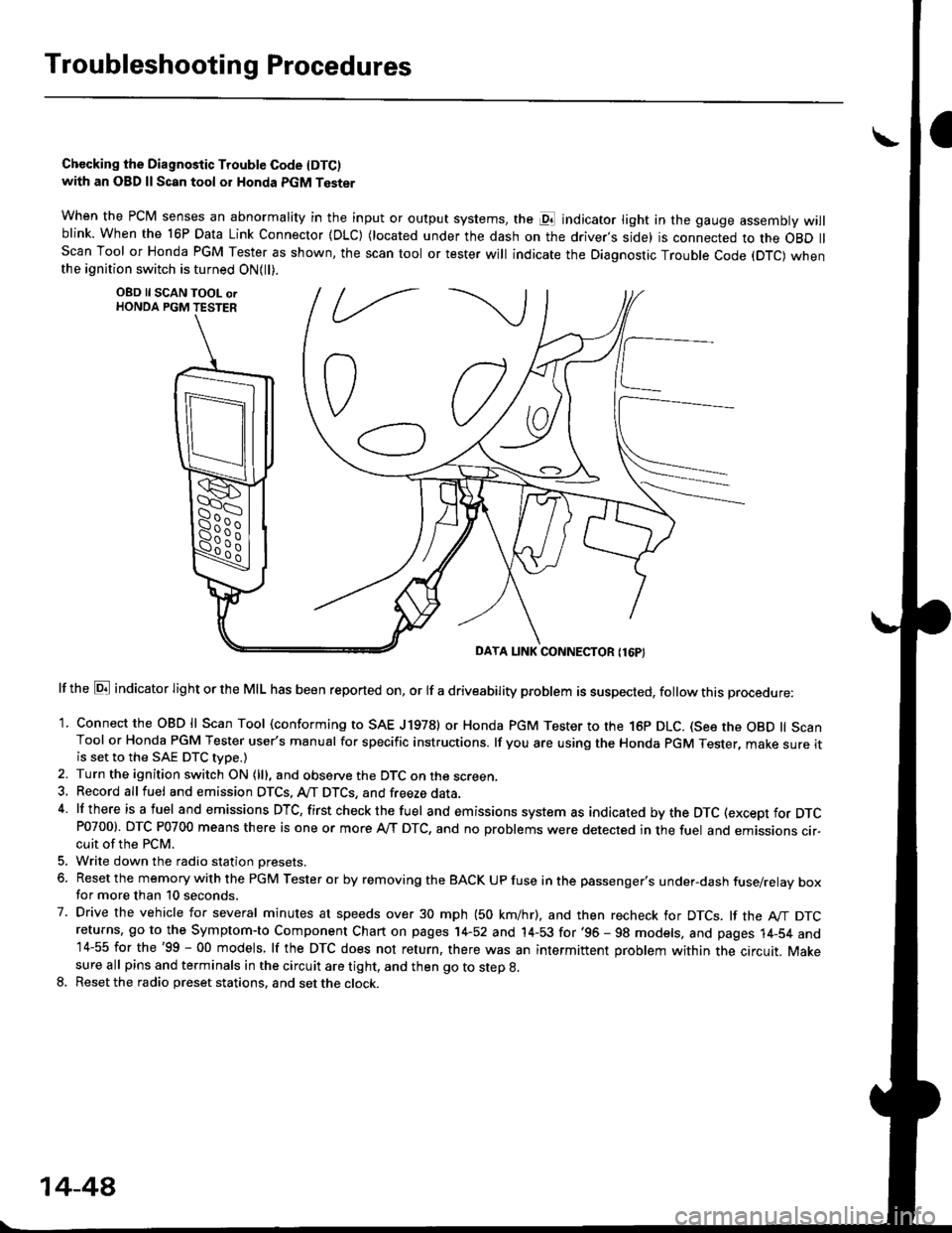
Chccking the Diagnostic Trouble Code IDTC)with an OBD ll Scan tool or Honda PGM Tester
when the PCM senses an abnormality in the input or output systems, the pl indicator light in the gauge assembly willblink. When the 16P Data Link Connector (DLC) (located under the dash on the driver,s side) is connected to the OBD llScan Tool or Honda PGM Tester as shown, the scan tool or tester will indicate the Diagnostic Trouble Code (DTC) whenthe ignition switch is turned ON{ll).
lf the El indicator light or the MIL has been reported on, or lf a driveability problem is suspected, follow this procedure:
1. Connect the OBD ll Scan Tool (conforming to SAE J19781 or Honda PGM Tester to rhe 16p DLC. (See the OBD ll ScanTool or Honda PGM Tester user's manual for specific instructions. lf you are using the Honda PGM Tester, make sure itis set to the SAE DTC type.)
2. Turn the ignition switch ON (lll, and observe the DTC on the screen,3, Record all fuel and emission DTCS, A/T DTCS, and freeze data.4 lf there is a fuel and emissions DTC, first checkthe fuel and emissions system as indicated bythe DTC (except for DTCP0700). DTC P0700 means there is one or more A,/T DTC, and no problems were detected in the fuel and emissions cir-cuit of the PCM.
5. Write down the radio station oresets.
6. Reset the memory with the PGM Tester or by removing the BACK UP fuse in the passenger's under-dash fuse/relay boxfor more than 10 seconds.
7. Drive the vehicle for several minutes at speeds over 30 mph (50 km/hr), and then recheck for DTCS. lf the A"/T DTCreturns, go to the Symptom-to Component Chart on pages 14-52 and 14-53 for'96 - 98 models, and pages 14-54 and14-55 for the'99 - 00 models, lf the DTC does not return, there was an intermittent problem within the circuit. Makesure all pins and terminals in the circuit are tight, and then go to step g.
8. Reset the radio preset stations, and set the clock.
OBD ll SCAN TOOL orHONDA PGM TESTER
DAYA LINK CONNECTOR {16P}
14-44
Page 727 of 2189

Chocking th€ Diagnostic Trouble Code (DTCI
with the Servico Check Conneqtor and Sp€cialTool
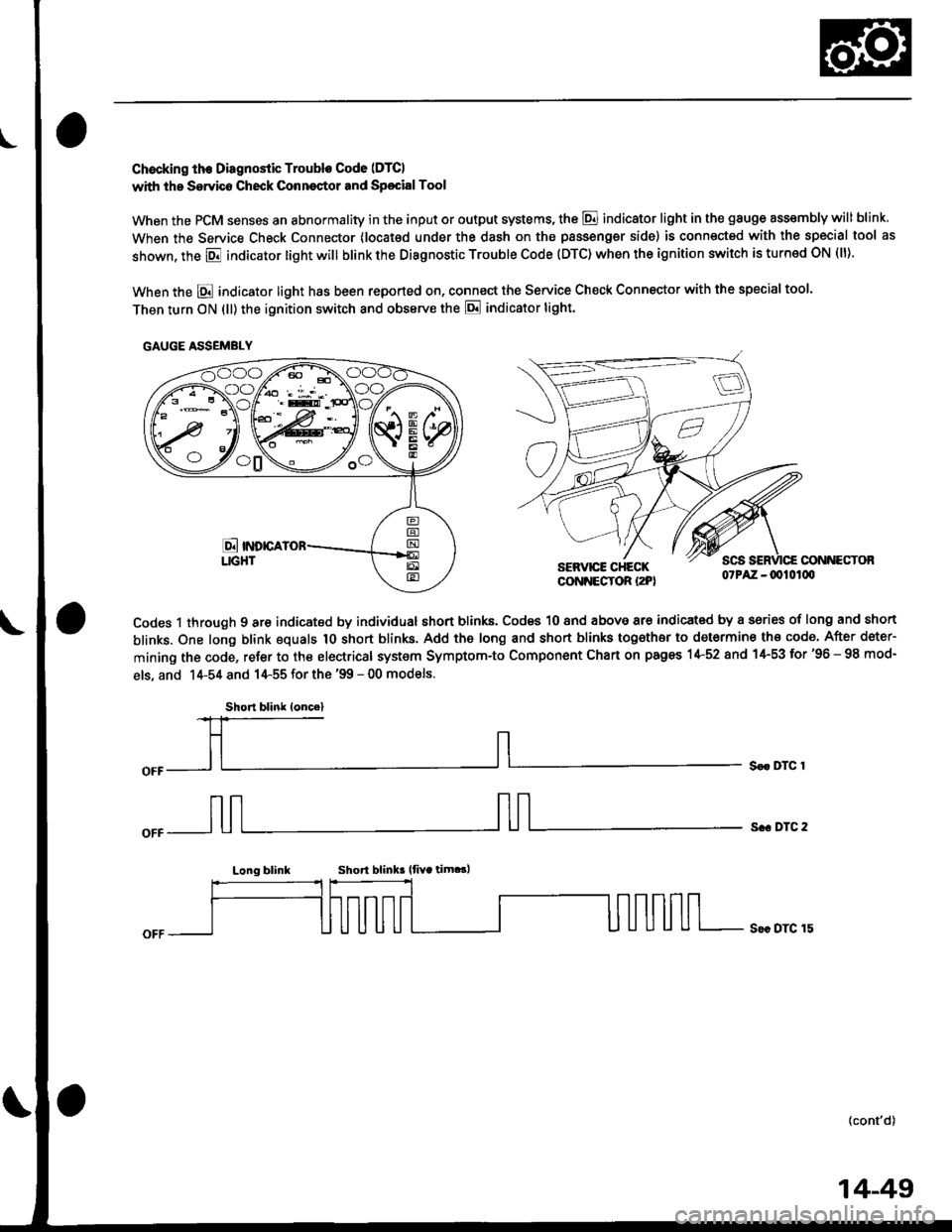
When the PCM senses an abnormality in the input or output systems, the @ indicator light in the gauge assembly will blink
When the Service Check Connector (locat€d under the dash on the passengsr side) is connected with the special tool as
shown, the E indicator light will blink the Diagnostic Trouble Code (DTC) when the ignition switch is turned ON (ll).
When the E indicator light has been reported on, connect the Service Check Connector with the special too'.
Then turn ON (ll) the ignition switch and obssrve the E indicator tight.
CONNECTOBSERVICE CHECKCONNECTOR I2PI07PAZ -0010100
Codes 1 through 9 are indicated by individual short blinks, Codes 10 and above are indicat€d by a sories of long and short
blinks. One long blink equals 1O short blinks. Add the long and short blinks together to determine th€ code. After deter-
mining the code, refer to the electrical system Symptom-to Component Chart on pages 1+52 and 1+53 for'96 - 98 mod-
els, and 14-54 and 14-55 for the '99 - 00 models.
S€r DTC 1
s.. DTC 2
Long blinkShort blink lfiYa tim.!,
S€c DTC 15
(cont'd)
GAUGE ASSEMBLY
Short blink loncel
14-49