Page 934 of 2189

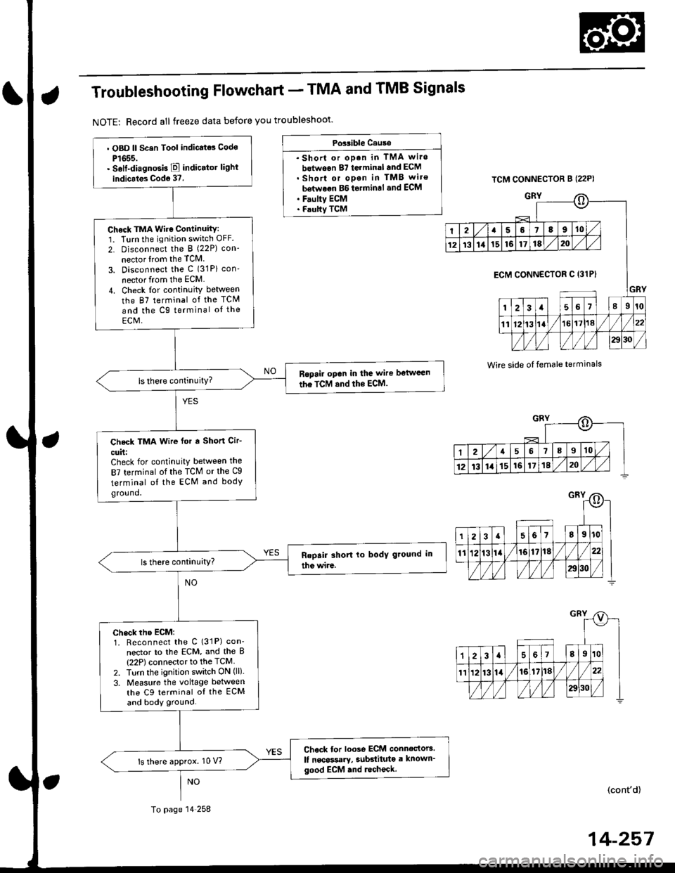
Troubleshooting Flowchart - TMA and TMB Signals
NOTE: Record all freeze data before you troubleshoot'
Possible Cause
. Shorl or op.n in TMA wi.o
botwo6n 87 terminal and ECM. Short or open in TMB wiro
bdtwoon BG to.min.l .nd ECM. F.ulty ECM. Faulty TCM
TCM CONNECTOR B (22P)
GRY
Wire side oI temale terminals
o
I2a58910
1213111516171820
GRY
ECM CONNECTOR C 13lPI
123a56l89r0
1112t3la1618//
29130 /
::)
I2a568910
12t3141516171820
. OBD ll Scsn Tool indicate3 Codo
P1655.. Self-diagnosb E indicator light
indicales Cod6 37.
Check TMA Wire Continuity:1. Turn the ignition switch OFF.
2- Disconnect the I (22P) con-
nector lrom the TCM
3. Disconnect the c (31P) con'
nector from the ECM
4. Check for continuity between
the 87 terminal of the TCM
and the Cg terminal oI the
ECM,
Ropail open in the wire betwcen
the TCM and the ECM.
Check TMA Wir€ for a Short Cir-
cuit:Check for continuity between the
87 terminal of the TCM or the Cg
terminal ol the ECM and bodyground.
check rhe EcM:1. Reconnect the C (31P) con'
nector to lhe ECM, and the B(22P) connector to the TCM
2. Turn the ignition switch ON (ll).
3. Measure the voltage between
the C9 terminal oI the ECM
and body ground.
Chock tor loose ECM connectors.
lf nscossary, subdituta a known'good ECM .nd lecheck.ls there approx. 10 V?
To page 14 258
(cont'd)
14-257
Page 940 of 2189

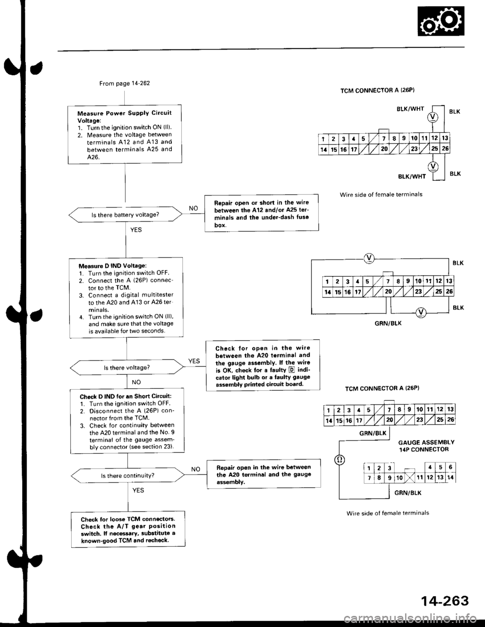
Ftom page 14 262
ls there battery voltage?
Measure Powet SUPPIY Ci.cuit
Voltage:1. Turnthe ignition switch ON (ll)
2. Measure the voltage between
terminals A12 and A13 and
between terminals A25 and
426.
Repair open or short in the wire
between the A'12 andlor Ms ler-
minrls and the under-dash fuse
DOX,
Measure D IND Voltage:1. Turn the ignition switch OFF
2. connect the A (26P) connec
tor to the TcM.
3. Connect a digkal multitester
to the A20 and A'13 or A26 ter
minals.4. Turn the ignition switch ON (ll),
and make sure that the voltage
is available for two seconds.
Check tor opon in the wire
between the A20 l6rminal and
the gaug€ assembly. It the wite
is OK, check tor a faultY ipl indi-
calor light bulb or a faulty gauge
assembly prir ed circuit boatd.
Check D INO for an Shott Circuit:1. Turn the ignition switch OFF
2. Disconnect the A (26P) con-
nector from the TCM.
3. Check for continuity between
the A20 terminal and the No. I
terminal of the gauge assem-bly connector (see section 23).
Bepair open in the wire between
the A20 terminal and the gauge
assembly.
Check tor looso TCM connecto.s.
Check the A/T ge.r Positionswitch. lf nec6ssary, substitute a
known-good TCM and r€check
BLK/WHTI
r
2a710111213
14t5161720232526
BLK/WHT
A
II
TCM CONNECTOR A I26P)
Wire side of female terminals
TCM CONNECTOR A (25P}
BLK
BLK
GRN/BLK
12a58910111213
1l15161720232526
o
GRN/BLK
GAUGE ASSEMBLY14P CONNECTOR
a5
78910111214
GRN/BLK
Wire side of female terminals
Page 966 of 2189
From page 14-289
Msaaure D IND Volt.ge:1. Turn the ignition switch OFF.
2. Connect tho B (25Plconnector
to the PCM.
3. Connect a digital multimeter
to the D14 and 820 or 822 ter-
mtnals.il. Turn the ignition switch ON(lll, and make sure that voltage
is available for two seconds
Check for open in the wire
between tha D14 terminal rnd
the gauge a33emblY. lf wiro ia
OK, chock for . frulty indicator
light bulb or a Iaulty gaug.
a3r6mbly printod circuit board.
Check D IND for a Short Circuit:
Check lor continuitY between the
D14 terminal and body ground.
Rgpair 3hort in the wire b.tween
the D14 tcrminal and tho gauge
a*somblY.
Check for loose terminsl fh in the
PCM connectors Check tho A/T
goar posilion switch. It neces'
saiy, iubstitute a known_good
PCM rnd rochock.
PCM CONNECTORS
D {16P1
(BRN/BI.X)D4 IND (GRN/BLK}
Wire side of female terminals
123rs 1/7I215
910nn fT /fl6l112
o lzlzz ,rl/zs 1311- -T---=4'+:l
LG2IBRN/BLKI\=/ |
r lz35
6i /l/t01112
l0
D' IND
o
IGRN/BLKI
4-289
Page 1333 of 2189
Door and Side Moldings
Replacement
CAUTION: When prying with a flat-tip scr6wdrivgr, wrap it with protective tape to prevent damags'
NOTE;
. To remove the front side molding, remove the inner fender (see page 20-106)'
. To remove the door moiding, remove the door panel (see pages 20-4, 10, 16) and plastic cover.
. To removethe rearside molding, remove the side trim panel (see pages 20-60,611'
. Take care not to bend the door moldings.
. Before reassembling, clean the door bonding surface with a sponge dampened in alcohol'
. After cleaning, keep oil, grease and water from getting on the surface'
. lf necessary, replace any damaged clips.
4D:
FRONT DOORAdhesive areas.
2Dl3Dl
B>,3c>,2
REAR SIDEMOLOING
a: Plastic nut loc€tion. 1
@)
(cont'dl
20-103
MOLDING
>: Clip locations
A >: 4D, 112')13D,7
Page 1337 of 2189
Opener Cable/Opener and Latch/Wiper and Washer
Component Location Index
2Dt3DItD'
y"Tl,"nll,ib?*'r.* o*t"
Replacement, Page 20_1 13
Adiustment, Page 20'1 17
WINDSHIELDWASHER NOZZLESAdjustment, Page 20_1 17
HOOD LATCH
{see page 20-110)
REAR WINDOW WIPER
ARM and MOTORReplacement, Page 20-1 15
Adjustment, page 20 117
LOCK CYLINDER(see page 20 113)
LOCK CYLINDER
TRUNK LIO LATCH
{see page 20 112)
FUEL LID OPENERCABLE(see page 20-108i
LID OPENERCABLE(see page 20 108)
LID/FUELLID OPENER(see page 20 111)
RELEASE HANDLE(see page 20-110)
3D:
REAR WINDOWWASHER NOZZLEAdiustment, page 20-1 17
REAR WINDOWWASHER TUBE(see page 20-116)
HATCH OPENERCABLE(see page 20 110)
WASHER RESERVOIRReplacement, Page 20-1 15
HATCH/FUEL LID OPENER(see page 20 1'11)
FUEL LID OPENERCABLE(see page 20 110)
(see page 20 111)
20-107
Page 1339 of 2189
TRUNK LID LATCH(see page 20'112)
?e-=....-
4D:
To trunk lidlatch.
latch.
TRUNK LID/FUELLID OPENER(see page 20 111)
TRUNK LID
OPENER CABLE
aA '--!
\- - -l
N"La
FUEL LIDOPEN€R CAELE
TRUNK LID/FUELLID OPENER(see page 20-111)FUELLATCH
(cont'd)
20-109
(see page 20'112)
Page 1340 of 2189

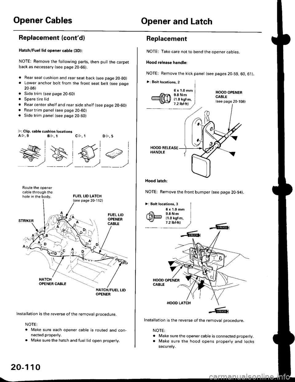
Opener CablesOpener and Latch
Replacement (cont'dl
Hatch/Fuel lid opener cable l3Dl:
NOTE: Remove the following parts, then pull the carpetback as necessary (see page 20-66).
. Rear seat cushion and rear seat back (see page 20-80). Lower anchor bolt from the front seat belt (see page
20 86)
. Side trim {see page 20-60). Spare tire lid
. Rear center shelf and rear side shelf {see page 20-60). Rear trim panel (see page 20-60). Side trim panel (see page 20,60)
>: Clip, cable cushion locationsa>.9B>, 1c>, 1D >,5
W#)
FUEL LID LATCH
#,
Route the openercable through thehole in the body.
HATCH/FUEL LIOOPENER
Installation is the reverse of the removal procedure.
NOTE:
. Make sure each opener cable is routed and con-nected properly.
. Make sure the hatch and fuel lid open properly.
page 20-112)
20-110
6x1.0mm j9.8Nm{1.0 kgf.m, i
Replacement
NOTE: Take care not to bend the opener cables.
Hood release handle:
NOTE: Remove the kick panel (see pages 20-59, 60.61).
>: Bolt locations, 2 ]I
HOOO OPENERCABLE(see page 20-108)
Hood latch:
NOTE: Remove the front bumper (see page 20-94).
>: Eolt locations, 3 I6 x '1.0 mm9.8 N.m11.0 kgf.m,
Installation is the reverse of the removal procedure.
NOTE:
. Make sure the opener cable is connected properly.. Make sure the hood opens properly and locks
securely.
Page 1342 of 2189

Opener and Latch
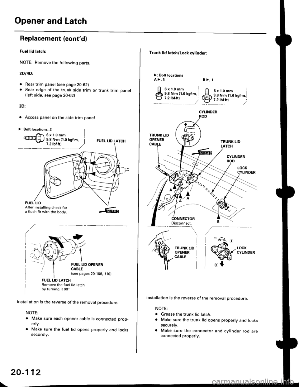
Replacement (cont'd)
Fuel lid latch:
NOTE: Remove the following pa(s.
2D l4Dl
. Rear trim panel (see page 20-62J. Rear edge of the trunk side trim or trunk trim panel(left side, see page 20-62)
3D:
. Access panel on the side trim panel
FUEL I-IO LATCH
II
FUEL LID OPENERCABLE(see pages 20,108, 1'10)
FUEL LID LATCHRemove the fuel lid latchby turning it 90o
Installation is the reverse of the removal procedure.
NOTE;
o Make sure each opener cable is connectedelty
. Make sure the fuel lid opens properly andsecurely.
prop-
locks
>: Eolt locations, 2 |r'- 6x10mm9.8 N.m (1.0 kgf.m, I
FUEL LIDAfter installing check fora flush fit with the body.
\
20-112
Trunk lid latch/Lock cylinder:
>: Bolt locationsA >,3
6x1.omm i9.8 N.m (1.0 kgf.m,
:::^ _=)
TRUNK LIDOPENER
CONNECTORDisconnect.-\
TRUNK LIDOPENERCABLE
8>, 1
ff e rt.omm IZS 9.8 N.ln (1.0 kgt m,.ty 7.2-tbr.ftt ,/
CYLINOER
TRUNK LIDLATCH
CYLINDERROD
Installation is the reverse of the removal procedure.
NOTE:
. Grease the trunk lid latch.. Make sure the trunk lid opens properly and lockssecurely.
a Make sure the connector and cylinder rod areconnected property.