1996 HONDA CIVIC page 112
[x] Cancel search: page 112Page 416 of 2189

Check the ECM input vottage {lP-/
VS- lino):1. Turn the ignition switch OFF.
2 Turn the ignition switch ON (ll)
3. Measure voltage between
ECM connector terminals C24
Ch.ck the ECM:
1. Turn the ignition switch OFF
2. Disconndct ECM connector C
{31P){rom the ECM.
3. Check lor continuity between
body ground and ECM con
nector terminal C24
ls there more than 0.5 V?
- Repair open in the wire
betw€en ECM {C2{l and Pri-
ma.y HO2S {S€nsor 1 l.- Substitute a known-good ECM
and recheck. It symptom/indi
cation goes away. replace the
odginal ECM.
Check to. r short in the wi.e {lP-/
VS- lin6l:1. Disconnect the 8P connector
from the Primary HO2S lsen-
sor 1).2. Check tor continuity between
body ground and ECM connec-
tor terminal C24
Ropair short in the wire bstween
the Primary HO2S lsensor 1) and
ECM (C24).
Check the ECM output voltage
{VS+ linel:N4easure voltage between ECM
connectorterminals C25 and D11.
Check for a short in the wire (VS+
line):1. Turn the ignition switch OFF.
2. Disconnect ECM connector C
{31P) Irom the ECM.
3. Check {or continuity between
body ground and ECM con
nector terminal C25.
ls there mote than 0.5 V?
ECM CONNECTORS
lFrom page'11-146)c (31PlD {15P)
tP-/vs- tREolfemale termrnals
sG2(GRN/BLKI
(cont'd)
11-147
I23a68910
111213la15t6'171622
232a25272a2930
O rP-/vs-:Z taeot
,l23a55I910
1112131a151617t822
232125212AE30
0) {REDr
23a518910
l11213ta'15't6171822
2321E272A2930
[]) vs*I rwsrt
(To page 11- 148)(To page 11 148)
Page 418 of 2189

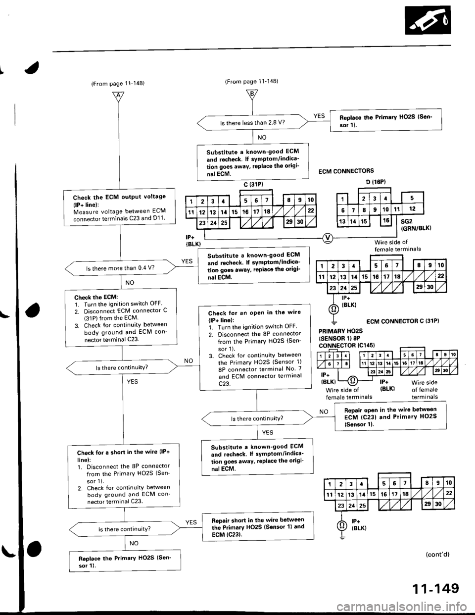
(From page 11 148)(From page 11'148)
Roplac€ th€ Primary HOzS (Sen'
sor 11.ls there lessthan 2.8 V?
Substitute a known-good ECM
and recheck. lf symptom/indica'
tion goes awav, replace th€ odgi'
nalECM.
Check the ECM oulput voltage
(lP+ linel:Measure voltage between ECM
connector terminals C23 and D11
Substitute a known-good ECM
and recheck f symptom/indica-
tion goes awaY, replace the origi_
nal ECM.
ls there more than 0.4 V?
Check the ECM:1. Turn the ignition switch OFF.
2. Disconnect ECM connector C(31Plfrom the ECM.
3. Check for continuity between
body ground and ECM con-
nector terminal C23
Check fot an oPen in tha wire
llP+ linel:1. Turn the ignition switch OFF.
2. Disconnect the 8P connoctor
from the Primary HO2S (Sen-
sor'l).3. Check for continuity between
the PrimarY HO2S (Sensor 1)
8P connector terminal No. 7
and ECM connector termrnal
c23.
Repair open in the wire belween
ECM {C231 and Primary HO2S
{Sensor 11.
Substitute a known_good ECM
and r6check. lf symPlom/indica'
tion goos away, replace the odgi-
nalECM.
Check for a short in the wire llP+
line):1. Disconnect the 8P connector
from the Primary HO2S {Sen'
sor 1),2. Check for continuity between
body ground and ECM con-
nector terminal C23.
Repair short in lhe wire belween
the Primary HO2S (Sensor 'l) dnd
ECM {C23).
Replace the Primary HO2S (Sen'
sor 1).
sG2(GRN/BLKI
Wire side offemale termanals
PRIMARY HO2S(SENSOR 1l8PcoNNECTOR lC1a5l
lP+(BLK)
Wire side of
female termrnalsof femaleterminals
NO
(cont'd)
123a68910
111213141516171822
2125a30
I lP+
6) tBrK)
ECM CONNECTOR C {31P}
23a67II10
1112131l15161118,422
232a25A30
A lP+Ij/ IBLK)
11-149
Page 485 of 2189

ldle Control System
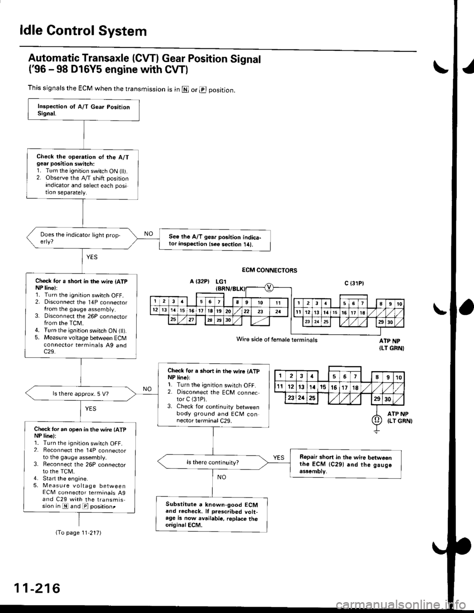
Automatic Transaxle (CVTI Gear Position Signal
('96 -98 D16Y5 engine with CW)
ATP NP{LT GRNI
INP
GBN)
This signals the ECM when the transmission is in @ or @ position.
Check the operation oI the A/Tgear position switch:1. Turn the ignition switch ON flt).2. Observe the A/T shift positionindicator and select each position separately.
See lhe A/T gear position indica-tor insp€ction {see sec{ion l/tl.
Check tor a short in the wir6 (ATpNP line):1. Turn the ignition switch OFF.2. Disconnect the 14P connectorIrom the gauge assembly.3. Disconnect the 26P connectorfrom the TCM.4. Turn the ignition switch ON fll).5. Measure voltage between ECMconnector terminals A9 andc29.
Check for a short in the wire lATpNP linell1. Turn the ignition switch OFF.2. Disconnect the ECM connector C (31P).
3. Check for continuity betweenbody ground and ECM connector terminal C29.
ls there approx. 5 V?
Check for an open in the wire lATpNP lina):1. Turn the ignition switch OFF_2. Beconnect the 14P connectorto the gauge assembly.3. Reconnect the 26P connectorto the TCM.4. Sta rt the engine.5. Measure voltage betweenECM connector terminals A9and C29 with the transmission in E and E posationt
Repair short in the wire betweenthe ECM {C291 and the gaugeassemblv,
Substitute a known-good ECMand recheck. lf prescribed volt-age is now avrilable, replace theo.iginalECM.
Wire side ot female terminals
2457I910
t112131a15151718
2321252930
ATP(LT io
(To page 11'217)
11-216
Page 763 of 2189

From page 14-84
Measule ATP NP Voltage:
1. Shift to all positions other thanpl or E.2. Measure the voltage between
the D13 and 820 or 822 termi-
nals.
Check for ahott in lhe wire
between ths D13 torminal and
tho A/T go.r PGition iwitci, and
in rho E .nd E polition signal
wires Mwgon tho A/T gsar Posi'tion indicrtor and th. A/T gGar
po3ition 3witch. ll wiJ.! .ro OK,
check lor loose torminal fit in the
PCM connoctor3. lf nocet3.rY,
substitute . known-good PCM
and r6check.
ls there baftery voltage?
Measure ATP D4 voh.g€:
1. Shiftto all positions otherthan
E2. Measure the voltage between
the Dg and 820 or 822 termi-nals.
Ch.ck lor 3hort in ths wilo
betweon tho lxl termin.l and tho
A/T ge.r pGhion switch. It wites
are OK. chock fo. looao t€rminal
fit in the PCM conn.ctoB. lf noc_
.*sary, sulFtitute a known-goodPCM .nd rechock.
ls there approx. 5 V?
Moa3ure ATP D3 Vohsge:
1. Shift to all positions other than
tr.2. Measure the voltage betweenthe D8 and 820 or 822 termi-
nals.
Check tor 3hort in the wits
betweon the D8 torminal and the
A/T goer position switch or A/Tgcar position indicltor. It wires
are OK, check for loo3€ torminalfit in tho FCM conn€ctoG. lf nec_
a3$ry, 3ubatitute e known'goodPCM and r.check.
ls there battery voltage?
To page l4'86
PCM CONNECTORS
o t16PlB {25P)
LGl (BRN/BLK)
g t25P)
LGl (BRN/8IJ()
LGl IBRN/BLK)
GRN)
D t16P)
IYEL)
231115 l68 112tV-s-
10n\/t7/ 167I910 t12
I
o zlzz /l/1,/ 113TIL---{O--l\=/LG2{BRN/BLKI
,/t\_
\a t9
ATP NP (LT
Wirc side o{ female termlnals
31158ll25
910111/t6l/17ls lt la112
20) W Wl/l '3111/ll
+LG2 (BBN/BLKI
-<_
ATP D4
LG2 (BRN/BLK}
14-85
Page 766 of 2189
![HONDA CIVIC 1996 6.G Workshop Manual Electrical Troubleshooting (gg - 00 Models)
Troubleshooting Flowchart - A/T Gear position Switch Open {cont,d)
PCM CONNECTORS
B l2sPlD {16P)
124156I
91011)./t5l/11189112
zo ztzzl l//l hsr),41
f ]_c;l HONDA CIVIC 1996 6.G Workshop Manual Electrical Troubleshooting (gg - 00 Models)
Troubleshooting Flowchart - A/T Gear position Switch Open {cont,d)
PCM CONNECTORS
B l2sPlD {16P)
124156I
91011)./t5l/11189112
zo ztzzl l//l hsr),41
f ]_c;l](/manual-img/13/6068/w960_6068-765.png)
Electrical Troubleshooting ('gg - 00 Models)
Troubleshooting Flowchart - A/T Gear position Switch Open {cont,d)
PCM CONNECTORS
B l2sPlD {16P)
124156I
91011)./t5l/11189112
zo ztzzl l//l hsr),41
f ]_c;l
j r-cz tgaNlelxr -ATP D4
Wire side of lemale terminals
(YEL}LGl {BRN/BI.KI
I.G1 IERN/BLKI
B (25P1
LGl IBRN/BLKI
D {16P}
From page 14-87
Moalure ATP 04 Vohago:1. Shift to pll position.2. Measure the voltage betweenthe Dg and 820 or 822 terminals.
Repair opon in the wire betweonthe lrg terminal and the A/T goatposhion switch.
Measure ATP D3 Vohage:1. Shift to l& position.2. Measure the voltage betweenthe D8 and 820 or 822 termi-nats.
Reprir opcn in the wirc b?twoenthe D8 terminrl and tho A/T goarDosition twitch.
Mersurc ATP 2 Voltage:1. Shift to E position.2. Measure the voltage betweenthe Dl4 and 820 or 822 termi-nals,
Reprir opon in the wire betweontho Dl4 te.minal rnd the A/Tgo.r position switch.
Ch6ck tor loose terminal tit in thePCM connectors. ll necossery,subslitute . known-good pCM
and recheck.
LG2IBRN/BLKI
I25l l6l/8
91011)/Itsln78912
ATP 2 IBLUI
t..
14-88
Page 790 of 2189

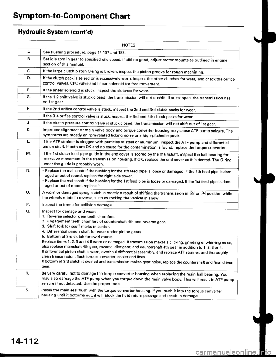
Symptom-to-Component Chart
Hydraulic System (cont'dl
G.
n,
set idle rpm in gear to specified idle speed. lf still no good, adjust motor mounts as outlined in enginesection of this manual.
lf the clutch pack is seized or is excessively worn. inspect the other clutches for wear, and check the orificecontrol valves, CPC valve and linear solenoid for free movement.
lf the linear solenoid is stuck, inspect the clutches for wear.
lmproper alignment or main valve body and torque converter housing may cause ATF pump seizure. Thesymptoms are mostly an rpm-related ticking noise or a high-pitched squeak.
lf the l st clutch feed pipe guide in the end cover is scored by the mainshaft, inspect the ball bearing forexcessive movement in the transmission housing. lf oK, replace the end cover as it is dented. The o-rinounder the guide is probably worn.
Replace the mainshaft if the bushing for the 4th feed pipe is loose or damaged. lf the 4th feed pipe is danFaged or out of round, replace the right side cover.
Replace the mainshaft if the bushing for the 1st feed pipe is loose or damaged. lf the 1st feed pipe is darn-aged or out of round, replace it.
A worn or damaged sprag clutch is mostly a result of shifting the transmission inthe wheels rotate in reverse, such as rocking the vehicle in snow.
or E position while
Inspect for damage and wear:
1. Reverse selector gear teeth chamfers.
2. Engagement teeth chamfers of countershaft 4th and reverse gear.
3. Shift fork for scuff marks in center.
4. Differential pinion shaft for wear u nder pin ion gears.
5. Bottom of 3rd clutch for swirl marks.
Replace items 1,2,3 and 4 if worn or damaged. lf transmission makes a clicking, grinding orwhirring noise,also replace mainshaft 4th gear, reverse idler gear. and countershaft 4th gear in addition to 1, 2, 3 or 4.lf differential pinion shaft is worn, overhaul differential assembly, and replace ATF strainer, and thoroughlyclean transmission, flush torque converter, cooler and lines.lf bottom of 3rd clutch is swirled and transmission makes gear noise, replace the countershaft and final drivengear.
Be very careful not to damage the torque converter housing when replacing the main ball bearing, you
may also damage the ATF pump when you torque down the main valve body. This will result in ATF pumpseizure if not detected. Use the oroper roors.
Install the main seal flush with the torque converter housing. lf you push it into the torque converterhousing until it bottoms out, it will block the fluid return passage and result in damage.
See flushing procedure, page 14-187 and 188.
lf the large clutch piston O-ring is broken, inspect the piston groove for rough machining.
lf the l-2 shift valve is stuck closed, the transmission will not upshift. lf stuck open, the transmission hasno 1st gear.
lf the znd orifice control valve is stuck. inspect the 2nd and 3rd clutch oacks for wear.
lf the 3-4 orifice control valve is stuck, inspect the 3rd and 4th clutch oacks for wear.
lf the clutch pressure control valve is stuck closed, the transmission will not shift out of 1st gear.
lf the ATF strainer is clogged with particles of steel or aluminum, inspect the ATF pump and differentialpinion shaft. lf both are OK and no cause for the contamination is found, replace the torque converter.
Inspect the frame for collision damage.
14-112
Page 868 of 2189

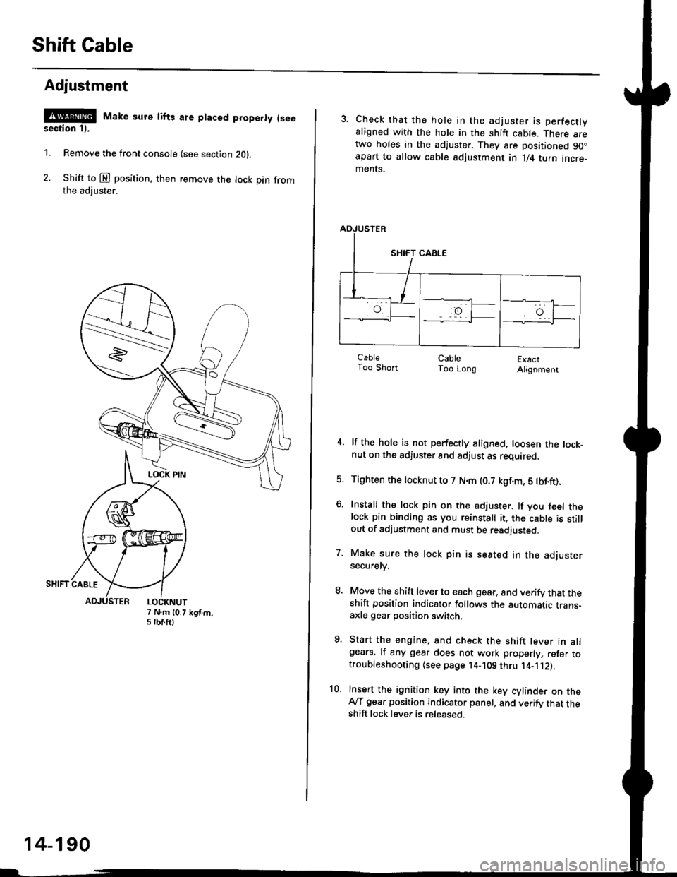
Shift Cable
Adjustment
@ Make sure lifts are ptaced properly (see
section 1).
1. Remove the front console (see section Z0l.
2. Shift to @ position. then remove the lock pin fromthe adiuster.
7 N.m (0.75 tbtftlkgtm.
14-190
3. Check that the hole in the adjuster is perfectlyaligned with the hole in the shift cable. There aretwo holes in the adjuster. They are positioned 90.apart to allow cable adjustment in 1/4 turn incre-ments.
ExactAlignment
4. lf the hole is not perfectly aligned, loosen the lock-nut on the adjuster and adjust as required.
5. Tighten the tocknut to 7 N.m (0.7 kgf.m, 5 tbf.ft).
6. Install the lock pin on the adjuster. lf you feel thelock pin binding as you reinstall it, the cable is stillout of adjustment and must be readjusted.
7. Make sure the lock pin is seated in the adjustersecuretv.
8. Move the shift lever to each gear, and verify that theshift position indicator follows the automatic trans-axle gear position switch.
9. Start the engine, and check the shift lever in allgears. lf any gear does not work properly, refer totroubleshooting (see page 14-109 thru 1'4-'112).
10. Insert the ignition key into the key cylinder on theAy'T gear position indicator panel, and verify that theshift lock lever is released.
CableToo ShortCableToo Long
Page 915 of 2189

Symptom-to-Component Chart
Electrical System -'96 - 98 Models
*: The DTC in parentheses is the code @ indicator light indicates when the Data Link Connector is connected to the HondaPGM Tester.
DTC*O Indicator
LightMILDetection ltemPage
P1790
(3)BlinksONThrottle position sensor14-242
P179'l
(4)BlinksONVehicle speed sensor14-243
P1705
(5)BlinksONAy'T gear position switch (short to groundl't 4-244
P1706
(6)OFFONA/T gear position switch {open)14-246
P0725
(11)BlinksONlgnition coil14-248
P1793
112lBlinksONManifold absolute pressure sensor14-249
P 1870(30)BlinksONShift control linear solenoid14-250
P'1873
(311BlinksONPH-PL control linear solenoid14-25'l
P1879(32)BlinksONStart clutch control linear sotenoid14-252
P1882BlinksONInhibitor solenoid14-253
P1885
(34)BlinksONDrive pulley speed sensor1l-Zb4
P1886(35)BlinksONDriven pulley speed sensor14-255
P1888
(36)BlinksONSecondary gear shaft speed sensor14-256
T to55
(37)BlinksONECM or TCM14-257
P1890
l42lBlinksONShift control system14-259
P1891
(43)BlinksONStart clutch control svstem14-260
14-23a