Page 165 of 2189

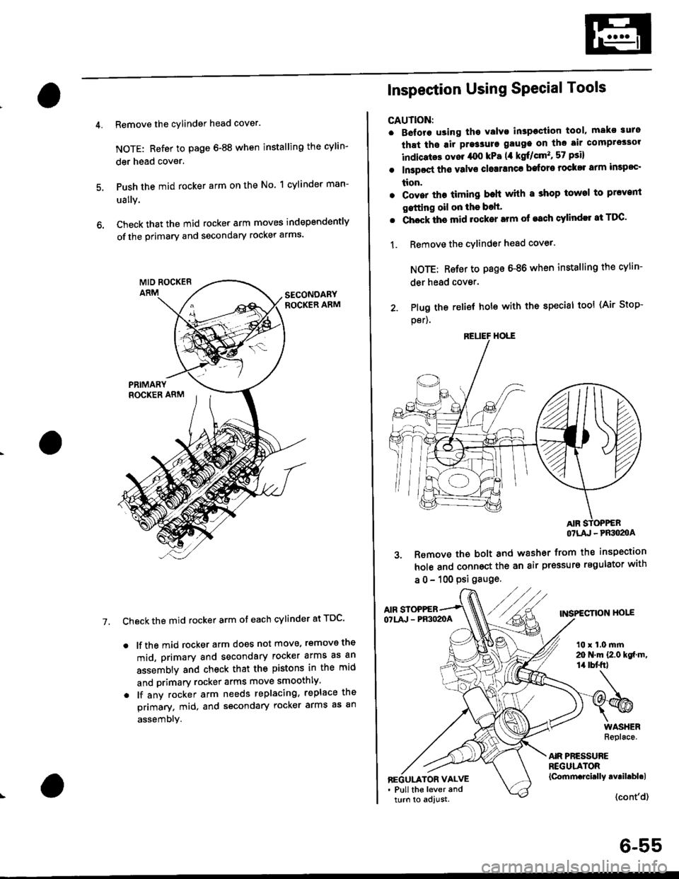
Remove the cylinder head cover.
NOTE: Refer to page 6-88 when installing the cylin-
der head cover.
Push the mid rocker arm on the No. 1 cylinder man-
ually.
Check that the mid rocker arm moves independently
of the primary and secondary rocker arms.
Check the mid rocker arm ot each cylinder at TDC'
. lf the mid rocker arm does not move, removs the
mid, primary and secondary rocker arms as an
assembly and check that the pistons in the mid
and primary rocker arms move smoothly.
. lf any rocker arm needs replacing, replace the
primary. mid, and secondary rocker arms as an
assembly.
7.
2. Plug the
per).
Inspection Using SPecial Tools
CAUTION:
. B€fore using tho Yalvo inspeciion tool, mako suro
that ths air pre3sure gauge on the air comprossor
indicatos ovor /rco kPa (,1 kgf/cm'�, 57 psi)
. In3poct ths valve closranca bafore rock$ arm impoc'
tion.
. Cover the timing beh whh I shop towel to prcvenl
gstting oil on the bolt'
. Chock ths mid rocker arm of each cylindll at TDC'
1. Remove the cYlinder head cover.
NOTE: Rsfer to page 6-86 when installing the cylin-
der head cover.
relief hole with the special tool (Air Stop-
OTLA' - PRSO2OA
3. Remove the bolt and washer from the inspection
hole and connoct the an air pressure regulator with
a 0 - 100 psi gauge.
AIF STOPPEBTNSPECTION HOIEOTLA' - PR3O2OA
t0 x 1.0 mrn20 N.m {2.0 kgf m,14 tbt'fr)
AIR PRESSUREREGULATOR{Cornm.rcirlly avril.bl.lBEGULATOR VALVE. Pull the lever andturn to adjust.{cont'd}
6-55
Page 179 of 2189
WATER BYPASS
HOSE
14. Remove the upper radiator hose, heater hose and
water bvpass hose.
HEATER
Remove the engine wire harness connectors and wlre
harness clamps from the cylinder head and the intake
manifold.
Four fuel injector connector
Engine coolant temperature (ECT) sensor connec-
tor
ECT gauge sending unit connector
ECT switch connector
ldle air control (lAC) valve connector
Manifold absolute pressure (MAP) sensor connec-
tor
Throttle position sensor connector
Primary Heated oxygen sensor (Primary HO2S)
connecror
VTEC solenoid valve connector
15.
a
a
a
a
a
\
16.
17.
Remove the spark plug caps and distributor form
the cylinder head.
Remove the upper bracket.
NOTE:
. Use a jack to support the engine before removing
the upp€r bracket is removed.
. Place a cushion between the oil panandthejack.
12 x 1.25 fin74 N.m 17.5 kgtm,
UPPER BRACKET
18. Remove the cylinder head cover.
{cont'd)
6-69
Page 183 of 2189
Rocker Arms and Lost Motion Assemblies
Inspection
NOTE: When reassembling the primary rocker arm, care-
fully apply air pressure to the oil passage of the rocker
arm.
PRIMARY ROCKER ARM
MID ROCKER ARM
Inspect each rocker arm piston. Push it manually
- lf it does not move smoothly. replace the rocker
arm assemDly.
1.
SECONDARY
Check prston movement
NOTE:
. Apply oilto the pistons when reassembling.
. Bundle the rocker arms with a rubber band to
keep them together as a set.
PISTONS
PRIMARY
\
6-73
2. Remove the lost motion assembly from the cylinder
head and inspect it. Test it by pushing the plunger
with your finger,
- lf the lost motion assembly does not move
smoothly, replace it.
LOST MOTION ASSEMBLY
Push
I
Page 191 of 2189

7. Apply a thin coat of clean engine oil to the outside
of the new valve guide. Install the guide from the
camshaft side of the head; use the special tool to
drive the guide in to the specified installed height. lf
you have all l6 guides to do, you may have to reheat
the head,
VALVE GUIDE DRIVER,5.5 mm077i12 - (x)l01(x)
tr A\
Valve Guide Installed Hoight:
lntake: 12.55 - 13.05 mm {0.,194 - 0.514 in)
Exhaust: 12.55 - 13.05 mm 10.494 - 0.51'l in)
VALVE GUIDE
\
Reaming
NOTE: For new valve guides onlY.
1. Coat both reamer and valve guide with cufting oil.
2. Rotate the reamer clockwise the full length of the
valve guide bore.
Continue to rotate the reamer clockwise while
removing it from the bore
Thoroughly wash the guide in detergent and water
to remove any cutting residue.
Check clearance with a valve lsee page 6-73)
. Verify that the valve slides in the intake and
exhaust valve guides without exertlng pressure.
REAMER HANDLE
Turn r6amer in
clockwise direction
a
VALVE GUIOE REAMER. 5.5 mm
OTHAH - PJTO1IIB
6-81
Page 227 of 2189
Engine Lubrication
SpecialTools .......... "'.""".8'2
lllustrated Index ........... .'..' 8-3
Engine Oil
Inspection .....'......"....."'. 8-6
Replacement........'......".'.'..."...."......" 8-7
OilFilter
Rep1acement...............".'...'..'.....'.'...". 8-8
Oil Pressure
Testing '.....' 8-9
OilJet (B16A2 engine)
Inspection ...'.'......"...."'..8-10
OilPump
overhaul.'... .....'...'..'."""' 8-11
Removal/lnspection/lnstallation ..'.... 8-1 3
Page 229 of 2189
lllustrated Index
NOTE:
. Use new O-rings when reassembling
. Apply oil to O-rings before installation
. Use liquid gasket, Part No 08718 - 0001 or 08718 -
0003.
CAUTION: Do not overiighten the drain bolt.
6x1.0mm12 N.m (1.2 kqtm,8.7 lbl.ftl. Clean the oil
Ing.
B1642 engine:
pan gasket mating surlaces before install-
WASHERRePlace'
DRAIN BOLT44 N.m (4.5 kgl'm,33 lbt'ft)
Do not overtrghten.
6x1.0mm11 N.m (1.1 kgtm,
OIL PANReler to page 7'27
when installing.
OIL PANGASKETReplace-
6x1.0mm11 N'm (1.1 kgl.m,8 lbf.ft)
OIL BREATHERCHAMEER8
otLSCREEN
GASKETReplace.
€!
fl
[50
BAFFLE PLATE
OIL JET BOLT16 N'm 11.6 kgf.m, 12lbt'ttl
OIL JETInspection, page 8-10
8x1+5mm24 N.d\l2.il kgf.ft,t7 tbtft)
OIL FILTERReplace.
ENGINE OIL PRESSURE SWITCH
Pipe Taper) 28 Threads/inch Clean
Use proper liquid sealant.
6x1.0mm11 N.m 11.1 kgt m,8 tbt.frl
Overhaul. page 8'11Removal/lnspection, Page 8-13
Apply liquid gasket to (cont,d)mating surface of engine block
Replacemenl, page 8-8
Replace.
8-3
Page 231 of 2189
NOTE:
. Use new O-rings when reassembling.
. Apply oil to O-rings before installation.
. Use liquid gasket, Part No 08718 - 0001 or 08718 -
0003.
. Clean the oil pan gasket mating surfaces before install-
Ing.
D16Y5, D16Y8 engines:
O.RINGReplace.
OIL PUMPOverhaul, Page 8 12
Inspection, Page 8 13 OOWEL PINApply liquid gasket
to the mating surface
of the block.
CAUTION: Do not overtightsn the drain bolt.
ENGINE OIL PRESSURE SWITCH18 N,m l'1.8 kgf.m, 13 lbf.ftl
1/8 in. ESPT (British
Standard Pipe Taper)28 Threads/inch. useproper liquid sealant.
O-RING
OIL BREATHERCHAMBER
6x1.0mm11 N.m {1.1 kgf.m,I tbt'ftl
6 x'1.0 mm11 N.m ('1.1 |8 tbf.ft)
GASKETReplace.
FILTERReplacement, page 8_8
BAFFL€ PLATE
6x1.0mm11N.m 11.1 kgl.m,8 tbf.ftl
6x1.0mm11 N.m 11.1 kg{'m,
8 rbf.ftl
OIL PANGASKETFeplace.
OIL PANReler to page 7 26when installing.
\3
6x1.0mm12 N.m {1.2 kg{.m,8.7 lbf ftl
BOLT39 N.m (4.0 kgf.m.29lbtftlDo not overtighten.
\
8-5
Page 235 of 2189

Oil Pressure
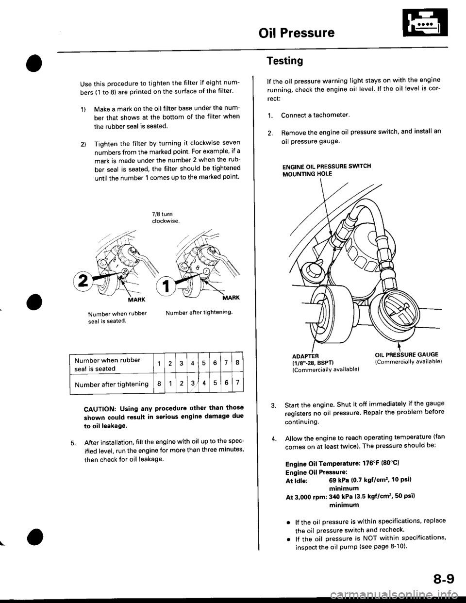
Use this procedure to tighten the filter if eight num-
bers (1 to 8) are printed on the surface of the filter.
1) Make a mark on the oil filter base under the num-
ber that shows at the bottom of the filter when
the rubber seal is seated.
2l Tighten the filter by turning it clockwise seven
numbers from the marked point. For example, if a
mark is made under the number 2 when the rub
ber seal is seated, the filter should be tightened
until the number 1 comes up to the marked point'
7/8 turn
Number when rubDer
seal is seated
Number after tightening.
CAUTION: Using any procedure other than those
shown could rosult in serious engins damage due
to oil leakage
5. After installation. fill the engine with oil up to the spec-
ified level, run the engine for more than three minutes,
then check for oil leakage
MARK
Number when rubber
seal is seated578
Number after tightening8151
Testing
lf the oil pressure warning Iight stays on with the engine
running, check the engine oil level. It the oil level is cor-
rect:
1. Connect a tachometer'
2. Remove the engine oil pressure switch, and install an
oal pressure gauge.
ENGINE OtL PRESSURE SWITCH
MOUNTING HOLE
ADAPTER(1/8\28. BSPTI
{CommerciallY availablei
Start the engine. Shut it off immediately if the gauge
registers no oil pr€ssure. Repair the problem before
continuing.
Allow the engine to reach operating temperature (tan
comes on at least tlivice). The pressure should be;
Engine Oil Temperature: 176"F (80"C1
Engine Oil Pressulo:
At ldle: 69 kPa (0.7 kgf/Gm'�. 10 Psi)
minimum
At 3.000 rpm: 3/Ut kPa (3.5 kgt/cm'�, 50 psi)
minimum
. lf the oil Dressure is within specifications, replace
the oil pressure switch and recheck.
. lf the oil pressure is NOT within specifications,
inspect the oil pump (see page 8-10).
OIL PRESSURE GAUGE(Commerciallv available)
8-9