Page 116 of 2189

(From page 6'4)
Test the VTEC Solenoid Valve:1. Turn the ignition switch OFF.2. Disconnect the wEC solenoidvalve 1P connector.3. Attach the battery positave
terminal to the VTEC solenoidvalve terminal.4. Start the engine and checkthe oil pressure at enginespeed of 5,000 rpm.
Inspect lhe VTEC solonoid valve
lsee p6ge m).ls the pressure above 390 kPa(4.0 kgtcm'�,57 psi)?
Test the VTEC Pressure Switch:With the battery positive terminalconnected to the VTEC solenoidvalve, measure voltage betweenthe ECM/PCM connector terminal'96 - 98: Cl5,'99 - 00: C10 andbody ground.
ls there battery voltage above5,000 rpm?
T6st the VTEC Solenoid Valvewire:1. Turn the ignition switch OFF.2. Check for continuity betweenthe VTEC solenoid valve 1Pconnector terminal and theECM/PCM connector terminal'96 - 98: A8, '99 00r B'12.
Repair open in the wire betweenthe ECM/PCM ('96 - 98: A8, '99 -
0o: 8l2l and VTEC solenoid v.lv6connoc{or.
Test the VTEC Solenoid Valve
Check for continuity between theVTEC solenoid valve 1P connectorterminal €nd body ground.
ReDair 3hort in the wire betweenthe ECM/FCM ('96 - 98: A.8, '99 -
0O: Bl2l and VTEC aolenoid valveconnectot,
ls there continuity?
Substitute a known-good ECM/PCM and recheck. lf symptom/indication goes away, replacethe original ECM/PCM.
VTEC SOLENOID VALVE1P CONNECTOR
Terminalside ofmale terminal
ECM/PCM CONNECTOR C {31P}
'99 - 00:'96 - 98:
CONNECTOR
'99 - 00:
VTEC SOLENOIDVALVE
ECM/PCM CONNECTORB {25Pt1P CONNECTOR'96 - 98:
VTEC SOLENOIDVALVE
ECM/PCM CONNECTOR
A {32P1
VTS{GRN/YEL)
wire side o{ femaleterminals
wire side oI temaleterminals
VTM
Page 117 of 2189
VTEC Solenoid Valve
Inspection
1.
6x1.0mm12 N.m 11.2 kgf.m,8.7 lbtft)
Disconnect the 1P connector from the VTEC sole-noid valve.
Measure resistance between the terminal and bodyground.
Resistance: l4 - 30 O
lf the resistance is within specifications, remove theVTEC solenoid valve assembly from the cylinder
head, and check the VTEC solenoid valve filter for
cloggrng.
. lf there is clogging, replace the engine oil filterand the engine oil.
VTEC SOLENOID VAI-VE ASSEMBLY
6-6
(
4. lf the filter is not clogged, push the VTEC solenoidvalve with your finger and check its movement.
. lf the VTEC solenoid valve is normal. check the
engane oil pressure.
6x1.0mm12 N.m {1.2 kgt.m,8.7lbf.ft)
I
.(
I
\
;
..l'
Page 140 of 2189

13. Remove the upper radiator hose' heater hose and
water bYPass hose
WATEREYPASSHOSEUPPERRADIATORHOSE
14.
HEATERHOSE
Remove the engine wire harness connectors and
wire harness clamps from the cylinder head and the
intake manifold.
o Four fuel injector connectors
. Engine coolant temperature (ECT) sensor con-
nector
a
a
a
ECT switch connector
ECT gauge sending unit connector
Throttle position sensor connector
Manitold absolute pressure (MAP) sensor con-
nector
Primary heated oxygen sensor (primary HO2S)
connector
Secondary heated oxygen sensor (secondary
HO2S) connector (D16Y7 engine)
Exhaust gas recirculation (EGR) valve lift sensor
connector (D16Y5 engine)
. VTEC solenoid valve connector (Dl6Y5, D16Y8
engrnes)
. VTEC pressure switch connector (D16Y5. D16Y8
engrnes,
. ldle air control (lAC) valve connector
15.Remove the spark plug caps and distributor from
the cylinder head.
Remove the uPPer bracket.
NOTE:
. Use a jack to support the engine before the
upper bracket is removed.
. Make sure to place a cushion between the oil
pan and the jack.
12 x 1.25 mm
74 N.m {7.5 kgf m.
sil lbl.ftl
UPPERBRACKET
'17. Remove the cylinder head cover'
CYLINDERHEAD COVER
(cont'd)
6-29
Page 145 of 2189
Rocker Arms and Lost Motion Assemblies
Inspection (D16Y5, Dt6Y8 enginesl
NOTEr When reassembling the primary rocker arm,carefully apply air pressure to the oil passage of therocker arm.
1. Inspect the rocker arm piston. push it manually.- lf it does not move smoothly, replace the rockerarm assembty.
Dl6Y5 engine:
ROCKER ARM
TIMING PISTON
TIMING SPRING
SYNCHRONTZINGPISTON
SECONDARYROCKER ARM
MID ROCKER ARM
PRIMARY ROCKER
SYNCHRONIZINGPISTON A
NOTE:
. Apply oil to the pistons when reassembling.o Bundle the rocker arms with a rubber band to preventthem from separating.
6-34
(\
DI6YS engine:
NOTE: Set the timing plate and return spring as shownoerow.
RETURN
CAMSHAFT HOLDER
Dl6Yg engine:
2. Remove the lost motion assembly from the holderand inspect it. Test it by pushing the plunger withyour finger.- lf the lost motion assembly plunger does notmove smoothly, replace it.
LOST MOTION ASSEMBLY
\a
Pu3h
I
Page 154 of 2189

Valves
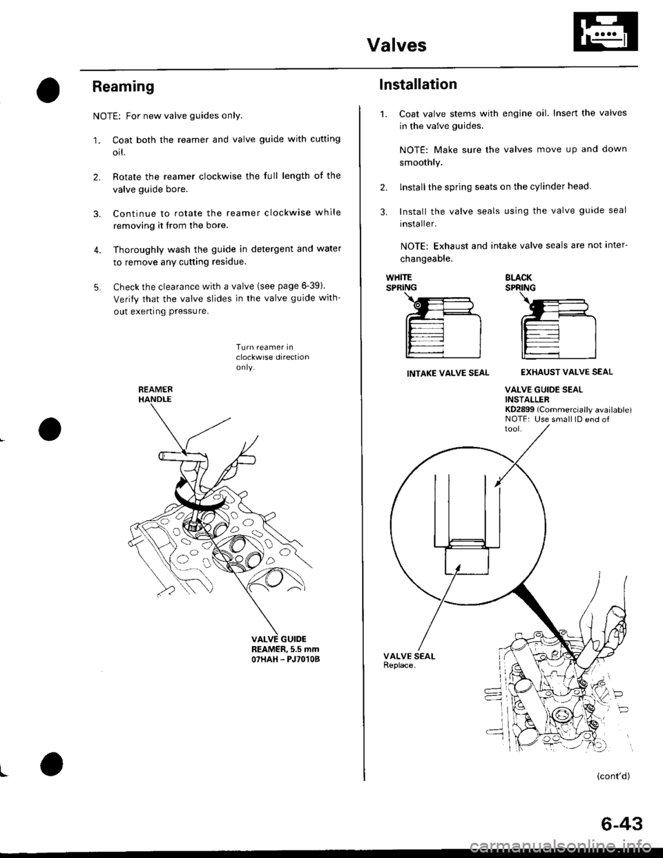
Reaming
NOTE: For new valve guides only.
1. Coat both the reamer and valve guide with cufting
orl.
2. Rotate the reamer clockwise the full length of the
valve guide bore.
3. Continue to rotate the reamer clockwise while
removing it from the bore.
4. Thoroughly wash the guide in detergent and water
to remove any cutting residue.
5. Check the clearance with a valve (see page 6-391.
Verify that the valve slides in the valve guide with-
out exerting Pressure.
Turn reamer inclockwise direclionon ly.
REAMER, 5.5 mmO7HAH. PJ'O'IOB
I
REAMER
oa)o,
o
o
1.
lnstallation
Coat valve stems with engine oil. Insert the valves
in the valve guides.
NOTE: Make sure lhe valves move up and clown
smoothly.
lnstallthe spring seats on the cylinder head.
Install the valve seals using the valve guide seal
installer.
NOTE: Exhaust and intake valve seals are not inter-
changeable.
2.
3.
WHITESPRINGBLACKSPRING
INTAKE VALVE SEALEXHAUST VALVE SEAL
VALVE GUIDE SEALINSTALLERKD2899 (Commercially available)NOTE: Use small lD end of
P
(cont'd)
6-43
Page 162 of 2189

VTEC Control System
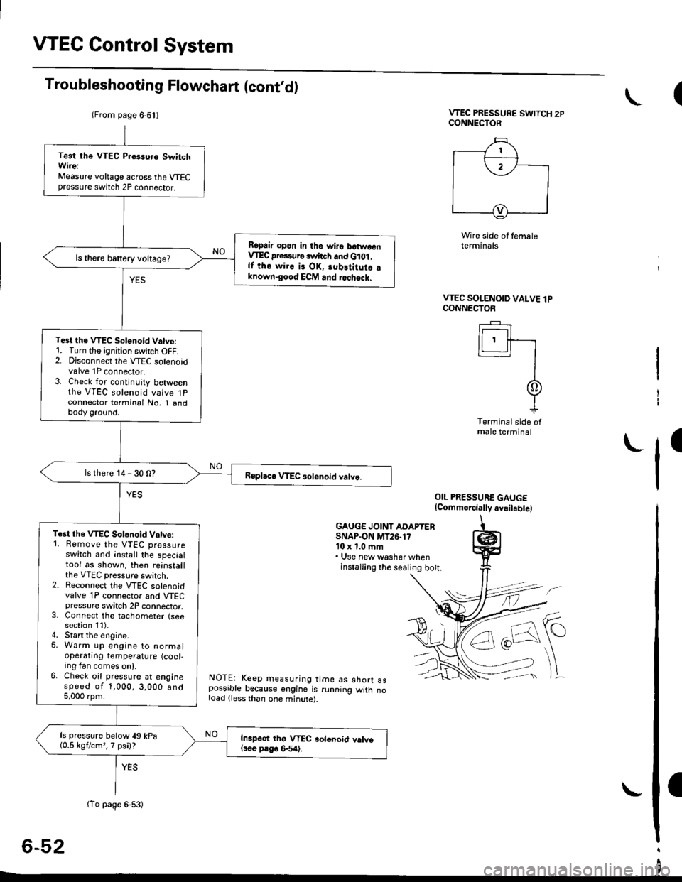
Troubleshooting Flowchart (cont,d)
VTEC PRESSURE SWITCH 2PCONNECTOR
Wire side of temaleterminals
OIL PRESSURE GAUGE(Comm.rcially avail.bte)
GAUGE JOINT ADAPTERSNAP.ON MT26.1710 x 1.0 ftm. Use new washer wheninstalling the sealing bott.
NOTE: Keep measuring time as shorr aspossible because engine is running witn noload lless than one minute).
6-52
(
VTEC SOLENOID VALVE lPCONNECTOF
Ir------r I
lLl.ll-r
II
It
Terminal side ofmale terminal
I
(From page 6-5l l
(To page 6-53)
Test tha VTEC P.es3uro SwitchWi.e:Measure voltage across the VTECpressure switch 2P connector.
Ropair opon in the wiro batwoenVIEC pr...urc switch and G lot .lf the wiro is OK, 3ubltitutr aknown-good ECM and rochack.
ls there battery voltage?
Test the VTEC Solenoid V.tve:1. Turn the ignition switch OFF.2. Disconnect the VTEC solenoidvalve 1P connector.3. Check for continuity betweenthe VTEC solenoid valve 1Pconnector terminal No, I andbody ground.
ls there 14 - 30 O?
Te3t the VTEC Sotonoid Vatve:'1. Remove the VTEC pressureswitch and install the specialtool as shown. then reinstallthe VTEC pressure switch.2. Reconnect the VTEC solenoidvalve 1P connector and VTECpressure switch 2P connector,3. Connect the tachometer (seesection 1l).4. Start the engine.5. Warm up engine to normaloperatrng temperature (cool-ing fan comes on).6. Check oil pressure at enginespeed of 1,000,3,000 and5,000 rpm.
ls pressure below 49 kPa(0.5 kgflcm,,7 psi)?Inipoct thg VTEC aolenoid valvel3ee P8go 6-54).
I
Page 163 of 2189

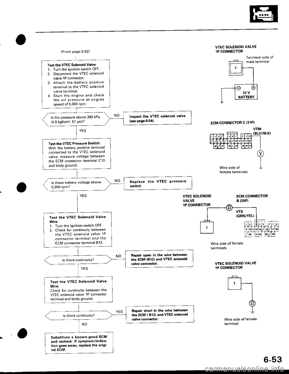
(From page 6-52)
Test the VTEC Solenoid Valve:
1. Turn the ignition switch OFF
2. Disconnect the VTEC solenoid
valve 1P connector,
3. Attach the batterY Posrtrveterminal to the VTEC solenoid
valve terminal.4. Start the engine and check
the oil Pressure at engine
speed ol5,000 rPm
lrcoect the VTEC solenoid valve(see page S54)ls the pressure above 390 kPa(4.0 kgt/cm?, 57 Psi)?
Test the VTEC Pressure Switch:
With the battery Positive terminal
connected to the VTEC solenoid
valve, measure voltage between
the ECM connector terminal C10
and body ground.
ls there battery voltage above
5,000 rpm?
Test the VTEC Solenoid Valve
Wire:1. Turn the ignition switch OFF
2. Check for continuitv between
the VTEC solenoid valve 1P
con nector terminal and the
ECM connector terminal 812
Repair open in the wire between
the ECM lB12| and VTEC aolenoid
Test lhe VTEC Solenoid Valve
Wire:Check for continuity between the
VTEC solenoid valve'lP connector
terminal and body ground.
Repair short in the wiro b€'tween
the ECM ( 812) and VTEC aolenoid
Substitute a known'good ECM
and recheck. lI sYmptom/indica'tion goes away. repleca the origi-
nal ECM.
VTEC SOLENOID VALVE
1P CONNECTOR
Terminal side ofmale terminal
VIEC SOLENOIDVALVE1P CONNECIOR
ECM CONNECTORB l2sP)
ECM CONNECTOR C (31PI
WM
Wire side ot female
termrnals
VTEC SOLENOID VALVE
1P CONNECTOR
I'ft
I
I
Wire side of female
termanal
6-53
Page 164 of 2189
VTEC Solenoid ValveVTEC Rocker Arms
a
I
(
Inspection
1. Remove the VTEC solenoid valve assembly fromthe cylinder head. and check the VTEC solenoidvalve filter for clogging.
. lf there is clogging, replace the engine oilfilter andengine oil.
6x1.0mm12 N.m (1.2 kgf.m, B,7 tbf.ftl
lf the filter is not clogged. push the VTEC solenoidvalve with your finger and check its movemenr.
. lf the VTEC solenoid valve is normal, check theengine oil pressure.
6x1.0mm12 N.m (1.2 kgtm,8.7 lbt.ft)
6-54
L-
SOLENOID
Manual Inspection
1. Set the No. 1 piston at TDC.
2. Remove the ignition wire cover and the wires.
3. Remove the ignition clamps while pulling up on theIock.
6xl.0mm9.8 N.m (1.0 kgl.m, 7.2 tbtftl
IGNITIONWIRE COVER
IGNITIONWIRE
\
LOCK