1996 HONDA CIVIC engine wire
[x] Cancel search: engine wirePage 179 of 2189
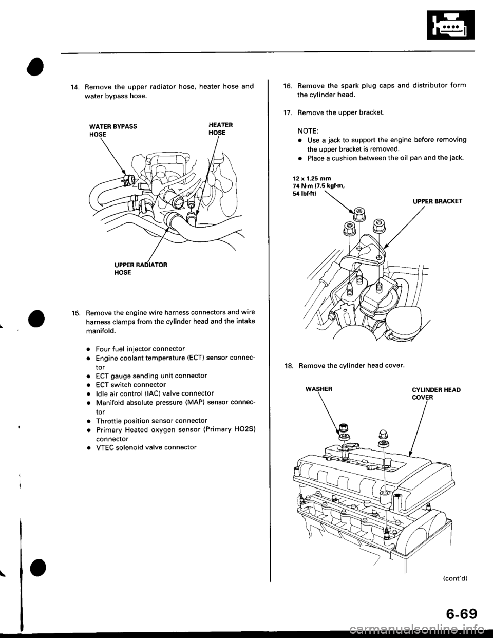
WATER BYPASS
HOSE
14. Remove the upper radiator hose, heater hose and
water bvpass hose.
HEATER
Remove the engine wire harness connectors and wlre
harness clamps from the cylinder head and the intake
manifold.
Four fuel injector connector
Engine coolant temperature (ECT) sensor connec-
tor
ECT gauge sending unit connector
ECT switch connector
ldle air control (lAC) valve connector
Manifold absolute pressure (MAP) sensor connec-
tor
Throttle position sensor connector
Primary Heated oxygen sensor (Primary HO2S)
connecror
VTEC solenoid valve connector
15.
a
a
a
a
a
\
16.
17.
Remove the spark plug caps and distributor form
the cylinder head.
Remove the upper bracket.
NOTE:
. Use a jack to support the engine before removing
the upp€r bracket is removed.
. Place a cushion between the oil panandthejack.
12 x 1.25 fin74 N.m 17.5 kgtm,
UPPER BRACKET
18. Remove the cylinder head cover.
{cont'd)
6-69
Page 207 of 2189

Main Bearing
Selection
CAUTION: lf the codes are indecipherable because of anaccumulation of dirt and dust, do not scrub them with a
wire brush or scraper. Clean them only with solvent ol
deiergent.
Crankshaft Bore Code Location
81642 engine:
Letters have been stamped on the end of the block as acode for the size of each of the 5 main journal bores.
Use them, and the numbers or bars stamped on the
crank {codes for main journal size), to choose the correct
beaflngs.
Main JournalCode Locations {Nombers or Barc)
Eearing ldentificationColor code rson lhe edge ofthe bear ng.Larger crank bore
acD
-----------""' Smallerbeanngtlhrcker)
9""1B':""
Alack
Black
Alue
7-10
\
D16Y5, D16Y7, D16Y8 engines:
Letters have been stamped on the end of the block as acode for the size of each of the 5 main journal bores.
Use them, and the numbers stamped on the crankshaft(codes for main journal size), to choose the correct bear-
Ings.
Main Journal Code Location (Numbers)
\
Color codeon theedge ofthe bearing-
Ldrger crank bore
Smaller bea ng {th'cker)
lr-l
t#lt+,tlf l 4 tlf '- 't
Smaller Smallermaan bearingjournal {thicker)
RedPinkGreen
PinkGreenBrown
GreenBrownBlack
GreenBrownBlackElue
I
Bearing ldentification
BcD
Page 217 of 2189
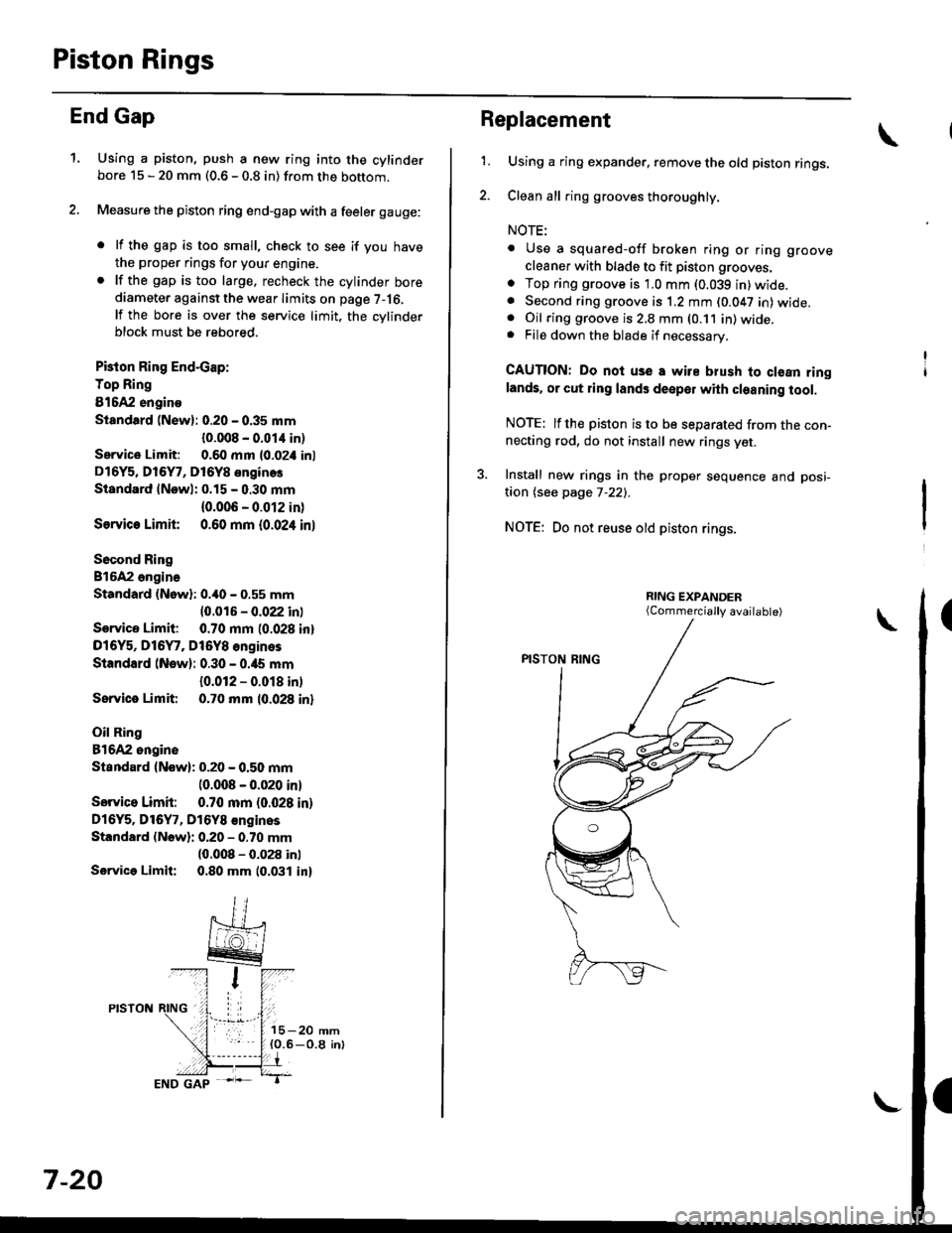
Piston Rings
End Gap
1.Using a piston, push a new ring into the cylinderbore 15 - 20 mm (0.6 - 0.8 in) from the bottom.
Measure the piston ring end-gap with a feeler gauge:
. lf the gap is too small, check to see if you have
the proper rings for your engine.. lf the gap is too large. recheck the cylinder borediameter against the wear limits on page 7-16,
lf the bore is over the service limit, the cvlinderblock must be rebored.
Pkton Ring End-cap:
Top Ring
81642 engino
Siandtrd (New): 0.20 - 0.35 mm
{0.008 - 0.01,1 in)
Service Limit: 0.60 mm l0-02i1 inl
D16Y5. Dl6Y7, D16Y8 enginos
Standard lNewl: 0.15 - 0.30 mm
{0.006 - 0.012 in)
Ssrvic€ Limit 0.60 mm {0.024 inl
Socond Ring
816A2 ongina
Standard (Nowl: 0.40 - 0.55 mm
10.016 - 0.022 inl
Service Limit: 0.70 mm (0.028 inl
D16Y5, D16Y7, Dt6Y8 engines
Standard (New): 0.30 - 0.ia5 mm
{0.012 - 0.018 in)
Sorvice Limit 0.70 mm 10.028 inl
Oil Ring
81642 ongine
Standard {Now): 0.20 - 0.50 mm(0.008 - 0.020 inl
Sorvico Limit: 0.70 mm (0.028 in)
Dl6Y5. Dl6Y7, D16Y8 €nginos
Standard (Nowli 0.20 - 0.70 mm(0.008 - 0.028 inl
Servica Limit: 0.80 mm 10.031 in)
7-20
Replacement
1.Using a ring expander. remove the old piston rings.
Clean all ring grooves thoroughly.
NOTE:
. Use a squared-off broken ring or ring groove
cleaner with blade to fit piston grooves.
o Top ring groove is 1.0 mm (0.039 in)wide.. Second ring groove is 1.2 mm (0.047 in) wide.. Oil ring groove is 2,8 mm (0.11 in) wide.. File down the blade if necessary.
CAUTION: Do noi use a wire blush to clean ringlands. or cut ring lands deepol with cleaning tool.
NOTE: lfthe piston is to be separated from the con-necting rod, do not install new rings yet.
3. Install new rings in the proper sequence and posi-
taon (see page 7-22).
NOTE: Do not reuse old piston rings.
(Commercially available)
Page 305 of 2189

System Description
Electrical Connections ('96 - 98 Models,'99 - 00 Dl6Y5 engine with M/Tl
(cont'dl
GA|l/OfiN
Cl3i C,ta6cart c5o2t--l c5t2
o",.uonr. l FSIX' {| | FYEI l
g
.lc5t0GRN/aaX: rdYEr. ILrGiN' -8rK/8ru -
BEo - -J
IGRN-_'-
8ru'--1
Orl0 C50il
LT
IYTENLOC|(CO TROT UMI
FronIAD|AtOh FAx
T' - RElAv EqtswIrEH
BLu/REo,- l f B!u/FEo,-----l ro a/c swrrcH
t_.1
,10: M/T {D16Y5..sin.l.11: Erc.pt M/l lOr5Y5.nginel'12: Ol6Y5, DlSYa.ngin.
'15: 97 Dl5Y7.ngin. {coup.: Klmod.l, $d.n:(l lLXlmod.ll, 9A DIOYT.nsin.
GRN/BIXI.
- LT GRflr-
T 8r"K/8ru
f"*
fr
ct3t c&t6
12: A/l (Dr5Y7, Dl6Y8.nglnelr3: CyI lOl5Y5..sinel'.: A/T.nd Dr6Y7.nsin.15: Erc.pt A/T .nd D16Y7.ngin6'5r A/i {Dl6Ya.ngin€l17: CVT (D16Y5 .noin.) rnd O16Ya .ngine'8r'96 015Y3 .ngin. lcoup.), 9t O16Ya sngin.(coop.r.llnod.l.,..d.n:KLmod.l), 98ol6Y5o.gins,'94 Di6YA .ngin., '99 - 0O D15Y5 lM/Tl 6ngin.
".*,".u---f
REo--__-
YEri -Gur{ -------
Brur- - l
L
- Etur
ArGEAR ?O6frO Swlrcs
1 1-36
Page 320 of 2189

System Connectors [Fuel Pumpl
'95 - 98 models, '99 - 00 Dl6Y5 engine with M/T:
ffi
c565
E
c792*r,.'5c793|.,.s
*1r USA mod€l'2: A/T {O16Y7, D16Y8 ensine}13: CVT {O16Y5 ensin€l*4: A/T ind D16Y7 .ngane*5: ExceFt A/T end D16Y7 engine'6: A/T lDl6Y8 enginel*7: CvT (Dl6Y5 enginoland 016Yg engine'8: ,96 Dl6YB engine {coupe),'97 Dl6Y8 sngine
{coupe: sll models, s€d.nr KL modell,'98 Dl5Y5.ngine,'98 D16Y7 engine,'99 - OO Dl6Y5 (M/Tl enginer9: D16Y5 onginet10: M/T {D15Y5 ensinelr1t: ExceDt M/T (D16Y5 engine)tl2: D16Y5, Dl6Yg engine*13: Dl6Y8 enginer14: D16Y7 engine*15:'97 Dl6Y7 ensine {coupe: KL model, sodan:
KL (LX) modeu,'98 Dt6Y7 engine
NOTE: . Different wires with the same color have been given a number suffix to distinguish them (for example' YEUBLK1
and YEVBLK'� are not the samel.
. O: Related to Fuel and Emissions System'
. - Connector with male terminals (dou ble outline): View f rom term inal side
- Connector with female terminals (single outline): View from wire side
c7931...15
ffi
1 1-51
Page 353 of 2189
Troubleshooting
Troubleshooting Procedures (cont,dl
CAUTION:
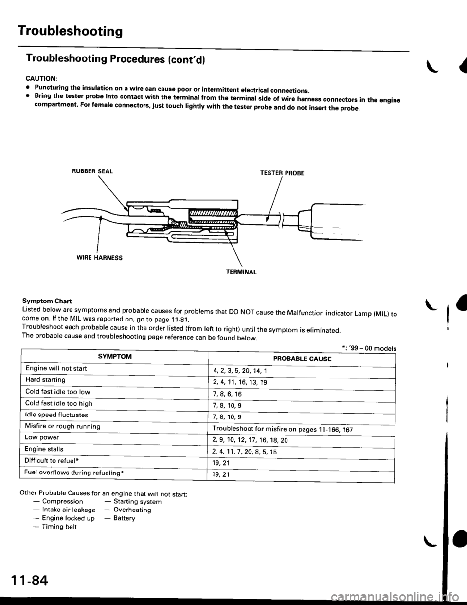
. Punqturing ihe insulation on a wirs can cause poor or intermiftent electricar connections.I Bring the test€r probe into contacl with the terminatlrom the terminal side of wire harnesg conncctors in the gngin€compartment. For temale connectors, iust touch lightly with the tester probe and do not inse.t the probe.
\I
RUBBER SEAL
Other Probable Causes for an engine that will not start:- Compression- Starting system- lntake air leakage - Overheating- Engine locked up - Battery- Timing belt
TESTER PROBE
Symptom Chart
Listed below are symptoms and probable causes for problems that Do NoT cause the Malfunction indicator Lamp (MlL) tocome on. lfthe MIL was reported on, go to page 11_81.Troubleshoot each probabre cause in the order risted (from reft to right) untir the symptom is eriminated.The probable cause and troubleshooting page reference can be found berow.
L
*: '99 - 00 models
TERMINAL
SYMPTOMPROBABLE CAUSE
4,2,3, 5,20, 14, 1
2, 4, 11, 16, 13, 't9
?, s^6. 16
1,8,10.9
Engine will not sta rt
Hard starting
Cold fast idle too low
Cold fast idle too high
ldle speed fluctuates7,8, 10.9
Troubleshoot for misfire on pages l1-166, 167Misfire or rough running
LOW power
E"g|* "t"lb
2,9, 10, 12, 11, 16, 't8,20
2,4,11,7,20,8,5,15
't9, 21
1r, ,1
Difficult to refuel*
Fuel overflows during refueling*
11-84
Page 357 of 2189
Troubleshooting
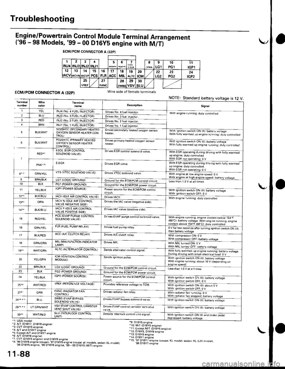
E n gine/P_o,weft ra in Control Module Term inal Arra n gement('96 - 98 Models, '99 - 00 Dl6yS engine with M/T)
-
ECM/PCM CONNECTOR A I32PI
1INJ62INJ3INJ21
INJl567I
LG110PGll1
IGPl12
ACV
131115
PCS
16
FLR17acc18MIL19ALTC20
tcM22PG221IGP2272A25
VSV30
SLU
ECM/PCM CONNECTOR A (32P)
'2: A./T (D16Y7, 016Y8 engine)13: CvT (D16Y5 enoin€)',4: A/T and D16y7 engine*5: Except A/T and D16Y7 €nsine'6r A/T (D16Y8 ensine)'7 Cw 1D16Y5 eng,nel and D16y8 ensrne'"'3:Bi..I?'Jt;".'e'.!ti.?i?l'""."T8"_";btfr
"fl
1-88
Wire side of female terminals
NOTE:Standard battery voltage12ts
'10i i,4/T (D16V5 engine)r11 Ex.ept M/l (D16V5 enqinelr12: 016Y5, D16YB enqine
r15:'97 016Y7 engine lcoupe: KL modet, sedan: KL (LXl modet),'98 D16Y7 engine
1
1
Sign.l
YELlNJ4 (No.4 FUEL INJECIOB)D ves No 4 ruel injector.Wilh engine runninq: ddly coniroted2BLUlNJ3 lNo. 3 FUEL TNJECTOBJDrives No. 3 lue Inteclor.38EDINJ2 (NO, 2 FUEI INJECTON)Drives No. 2 iuel njector.88NlNJl (No. 1 FUEL INJECTOB)Dives No. 1 ruelinjector.
5SO2SIITC (SECONDAFY HEATEDOXYGEN SENSOF HEATEF CONTFOL)
Orives secondary heated oxyqen sensorWith ignilion switch ON (lll: batery vo lageWith f!llywarmed up engine runninq:dLtv controled
6BLXAVHTPO2SHTC (PRIMAFY HEATEOOXYGEN SENSOR HEATERCONTROL)
Drives prihary healed oxygen sensorWith ignition switch ON ltt):baneryvottasewlhrdllywdrmedupcngne,Lnnrrq dury,orl.otred
FED{ESOL (EGF CONTRO!SOIENOIO VALVE)Drives EGF conlrolsoleno d vatve.Wilh EGR operating during drving wiih fu|y warmedup engrne: duty controttedWilh EGF nol opefating:O VE.EGRWith EGF operating du.ing driv og wilh iuty warmedup en9ine: dutycont.olted.With EGR not ooeralino; o V8*r/GFN/YELWS (VTEC SOLENOTD VALVE)Drives VTEC solenoid va veWilh eng ne at ow engine speed:O VWirh engine at h gh enqine speedr banery vohaae9BflN/BLKLG1 (LOGIC GROUND)Gro!nd lorthe €CM/PCM conlrotc rcuit.Lesslhan 1.0 V at a ttimest0ALKPG1 IPOWEF GFOUND)Ground ior rhe ECM/PCM power.tcuf.11YEVBLKIGPT iPOWEF SOUFCE)Power source forthe Ec[,l/PcM conlroWilh ignition swirch ON (tt): battery voltageWith gntron switch OFF: 0 VBLVBLUIACV (IDLE AIN CONTROL VALVE)Wilh engine r!nn ng: dlty contro ed13,.o8NIACV N lIDLE AI8 CONTFOLVALVE NEGATIVE SIOE)Drivesthe IAC valve {negalive side).
BLVBLUIACV P (IDLE AI8 CQNTROLVALVE POSITIVE SIDE)Orives IAC vaive (posilive side).
FEO/YELPCS (EVAP PURGE CONTFOTSOIENOIOVALVE)Drives EVAP pu.ge controtsolenoid vatve.Wilh engioe running, engin€ cootani betow 154,F'68'Cr bancry vohaSe w'ln ens nc runn,.o. eng,rc
GRN/YELFL8 (FUEL PU[4P FELAY)Orives fuelpump relay.0 V {or two secor os ahe' tJ n ng 'onir or \wnch ON ,,,,,
I7BLI(REOACC (A,/C CLUTCH RELAY)Drives A/C clutch relay.Wirh compressor ONr0 VWilh compressof OFF:banery votrage18GFN/ONNMIL (I\,lALFUNCTION INDICATOFWith MIL lLrned ON: 0 VWith illl turned OFF: banery volaqe19',AITC {AITERNAIOR CONIROL)se.ds ahernator controt signat.Wirh fully warmed.up engine ru.ntng: battery votlas€During drivins wnh smatl eteclricat toad: O V
20YEVGRNICM (IGNI'TION CONTROLMOOU!E)with ignltlon swilch ON (tl):b6n€ry vohageWilh ensine runnins: aboul t0 V (depending on
22BRN/BLKLG2 (LOGIC GAOUND)Ground for the ECM,/PCM conrrot ci'cu LLess than 1.0 V at a tt mes23BLKPG2 iPOWEA GROUND)Gro!nd lor the ECM/PCM power circuir.24YEUBLKlGP2 (POW€R SOUSCE)Power sou.ce lor the ECM/PCl, conrrolWnh ignilion swilch ON {it):battery vohageWilh ignilion switch OFF:0 V25*6WHT/FEDVSEF IREFEfl ENCE VOLTAGE)Provrdes reference voIaOe to TCM.With ignition switch ON (tt):abour 5 VWth gnition swltch OFF: O V21'1GFNFANC {RAOIATOR FANCONTFOL)Drives radialof fan ielay.With radialor fan f!nn nqr O VWilh radiato.tan stopped: batteryBL!2WBS (EVAP BYPASSSOLENOIO VALVE]Orives EVAP bypass sotenotd va !e.With ignirion swrrch ON (tt):barery vo rase
LT GRNA/VHTVSV (EVAP CONTFOTCANISTEFVENT SHUT VAIVE)Drives EVAP conlfot canisrer venl shulwnh ignirion sw'tch ON lr|l barery volaqe
WHT/NEDSLU (INTEFLOCK CONTFOLUNIT)Detects intenock conlrotLn t signalWhh ignition switch ON (tt)and brake pedadepf essed: battery vollage
Page 358 of 2189
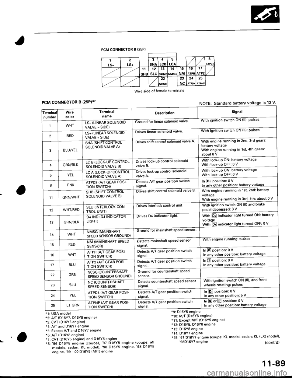
PCM CONNECTOR B {25P)
Wire side of {emale terminals
CONNECTOR B (25P)',
*1i USA model*2: A/T (D16Y7, Dl6Yg engine)*3: CVT (D16Y5 engine)*4: M and Dl6Y7 engane*5: Except A.rT and 016Y7 engine*6: A,/T (D16Y8 engine)*7r CVT (D16Y5 engine) and D16Y8 engine*8: '96 D16Y8 engine (coupe),'97 D16Y8
models, sedan: KL model),'98 Dt6Y5
engine,'99 00 Dl6Y5 1M/Ti engine
*9: D16Y5 engine*10: M/T (D16Y5 engine)*11: Except M/T {D16YS engine}*12i D16Y5, D16Y8 engine* 13: D16Y8 engine*14: D16Y7 engine*15: '97 Dl6YTengine (coupe: KL model, sedan: KL (LX) model)''98D16Y7 engine (cont,d)engine (coupe: allengine,'98 D16Y8
FCMNOTE: Standard battery voltage is 12 v'
erminalTnumoer
Wirecotol
TerminalnameDescriptionSignal
1LS_ (LINEAR SOLENOID
VALVE - SIDE)
Ground for linear solenoid valveWii-ignnion switctr oN {ll}: pulses
2REDLS+ (LINEAR SOLENOIDVALVE + SIDE)
-Drii6l linear solenoid valveWith ignilion switch uN (lll: pulses
3BLU/YEL
SHA {SHIFT CONTROLSOLENOID VALVE A)
-Drives shift control solenoid valve AWith engine running in 2nd,3rd gears:
battery voltageWith engine running in 1st,4th gears:
about 0 V
4GRN/BLKLC B (LOCK'UP CONTROL
SOLENOID VALVE B}Drives lock up control solenoid
valve B.
With lock-up ONI battery voltage
With lock-up OFF:0 v
5YELLC A (LOCK.UP CONTROLSOLENOID VALVE A)Drives lock up controlsolenoidWith lock-uP ON: baftery voltage
With lock-up OFFi 0 V
8PNKATPD3 (NT GEAR POSI.
TION SWITCHi
Detects Py'T gear Position switch
signal.
In [D31 position: 0 V
ln ;y other position: battery voltage
1lGRN^lr'HT
SHB (SHIFT CONTROLSOLENOID VALVE B)DnGs shift conttol solenoid valve BWith engine running in 1st,2nd: battery
vo|taqeWith;ngine running in 3rd,4th: about 0 V
12WHT/REDSLU (INTERLOCK CON
TBOL UNIT)
-DlivEilite'lock control,rnit.With ignition switch ON (ll) and brake
pedal depressed: 0 V
13GRN/BLK
D4 IND (D4 INDICATORLIGHT)
Drives D4 indicator light.With Pll indicator lrght turneo urr: oarterv
voltaoeWith ld indicator light turned OFF: 0 v
14WHTNMSG {MAINSHAFTSPEED SENSOR GROUND)
GZiiI'for mainshaft speed sensol
With engine running: Pulses
In E position: 0VIn any other position: battery voltage
REDNM {MAINSHAFT SPEED
SENSOR)
Detects mainshaft speed sensor
srgnal.
ATPR {M GEAR POSI
TION SWITCH)
Detects M gear Position switch
signal
't1BLUATP2 {A/T GEAR POSITION SWITCH)
Detects A/T gear Position switch
signal.
In E position: 0VIn any other position: battery voltage
22GRNNCSG (COUNTERSHAFT
SPEED SENSOR GROUND)Ground for countershaft speed
sensor.
23BLUNC (COUNTERSHAFT
SPEED SENSOR)
Detects countershaft speed sensor
signal.
Vvith ignition switch ON (ll), and front
wheels rotating: Pulses
24YELATPD4 {M GEAF POSI-
TION SWITCH)
Detects M gear Position switch
signal.
ln E position:0 VIn any other position: 5 V
25LT GRNATPNP (A"/T GEAR POSITION SWITCH)
Detects A/T gear Position switch
srgnal,
In E orE position:0 V
In any other position: battery voltage
!a
11-89