Page 727 of 2189

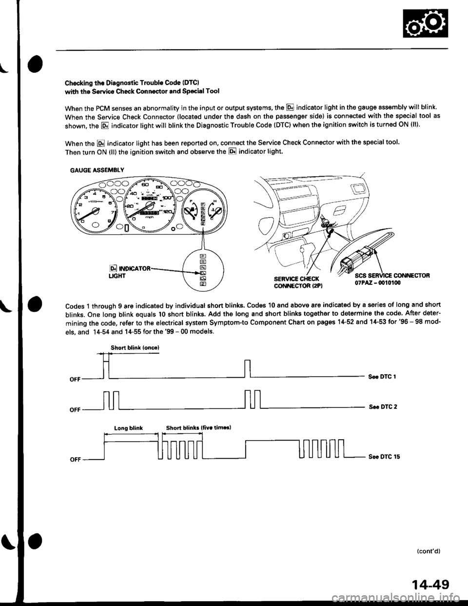
Chocking th€ Diagnostic Trouble Code (DTCI
with the Servico Check Conneqtor and Sp€cialTool
When the PCM senses an abnormality in the input or output systems, the @ indicator light in the gauge assembly will blink
When the Service Check Connector (locat€d under the dash on the passengsr side) is connected with the special tool as
shown, the E indicator light will blink the Diagnostic Trouble Code (DTC) when the ignition switch is turned ON (ll).
When the E indicator light has been reported on, connect the Service Check Connector with the special too'.
Then turn ON (ll) the ignition switch and obssrve the E indicator tight.
CONNECTOBSERVICE CHECKCONNECTOR I2PI07PAZ -0010100
Codes 1 through 9 are indicated by individual short blinks, Codes 10 and above are indicat€d by a sories of long and short
blinks. One long blink equals 1O short blinks. Add the long and short blinks together to determine th€ code. After deter-
mining the code, refer to the electrical system Symptom-to Component Chart on pages 1+52 and 1+53 for'96 - 98 mod-
els, and 14-54 and 14-55 for the '99 - 00 models.
S€r DTC 1
s.. DTC 2
Long blinkShort blink lfiYa tim.!,
S€c DTC 15
(cont'd)
GAUGE ASSEMBLY
Short blink loncel
14-49
Page 730 of 2189

Symptom-to-Component Ghart
Electrical System -'gG - 98 Models
*1: The DTC in the parentheses is the code E indicator light indicates when the Data Link connector is connected to theHonda PGM Tester.*2: Whenever the Honda PGM Tester or Scan Tool detects an automatic transmission control system DTC, p07OO will beset in the PGM-FI control svstem.
DTCIIE Indicaior
LightMILDotection ltemPage
P1753
fl)BlinksONLock-up control solenoid valve A14-56
P1758
\21BlinksONLock-up control solenoid valve B14-58
P1705
(51BlinksONAy'T gear position switch (short to groundl14-60
P1706
(6)OFFONA,/T gear position switch (open)14-62
P0753
l7lBlinksONShift control solenoid valve A14-64
P0758
{8)ElinksONShift control solenoid valve B14-66
POl20
(9)BlinksONCountershaft speed sensor14-68
P0715
{15)
'96 - 97
models:
OFF'98 model:
Blinks
ON
Mainshaft speed sensor
14-70
P1768
{16)BlinksONLinear solenoid't 4-72
P0740
(40)OFFONLock-up control system14-7 4
P0730
(41)OFFONShift control system14-75
P0700*,
(none)Automatic transmission control svstem in the pGM-Fl
control svstem
14-52
Page 732 of 2189

Symptom-to-Component Chart
Electrical System -'99 - 00 Models
*1: The DTc in the parentheses is the code E indicator tight indicates when the Data Link connector is connected to theHonda PGM Tester.*2: Whenever the Honda PGM Tester or scan Tool detects an automatic transmission control system DTc, p07oo will beset in the PGM-FI control svstem
DTC*IE Indicator
LightMILDotostion ltemPage
P1753
fi)BlinksONLock-up control solenoid valve A'14-80
P1758
t2lBlinksONLock-up control solenoid valve B14-82
P1705
{5}BlinksONAy'T gear position switch {short to ground)14-84
P1706
(6)OFFONy'VT gear position switch {open)14-81
P0753
\71BlinksONShift control solenoid valve A14-89
P0758
(8)BlinksONShift control solenoid valve B14-9r
P0720
(9)BlinksONCountershaft speed sensorr4-93
P0715
(15)B linksONMainshaft speed sensor14-95
P1768
(16)BlinksONLinear solenoid't 4-97
PO7 40(40)OFFONLock-up control system14-99
P0730
(41)OFFONShift control svstem14- 100
P0700*,
(none)OFFAutomatic transmission control system in the pGM_Fl
controt svstem
14-54
Page 734 of 2189

Electrical Troubleshooting (,96 - gg Models)
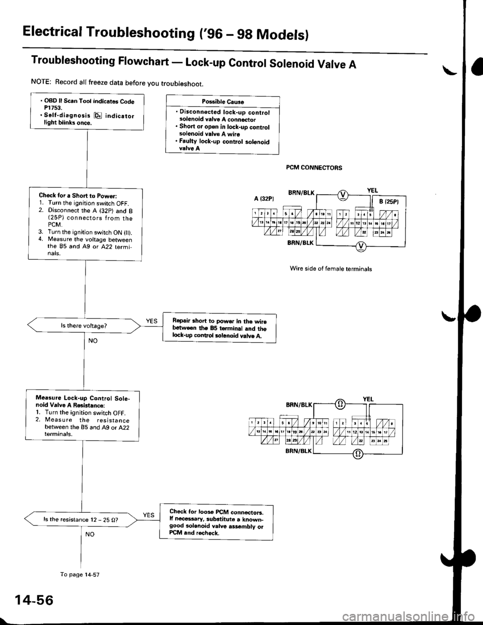
Troubleshooting Flowchart - Lock-up contror sorenoid Varve A
Po$ible Cau3e
. Disconnecled lock-up controlsolenoid valvo A connector. Short or open in lock-uD controlsolenoid valv€ A wire. Fauliy lock-up contlol solonoidvalve A
PCM CONNECTORS
Wire side of female terminals
. OBD ll Scrn Toot indicates CodeP1753.. Self-diagnosis @ indicatorlight blinks once.
Check for a Short to Powo.:1. Turn the ignition switch OFF.2. Disconnect the A (32p) and B(25P) connsgl6ps 1rq- thaPCM.3. Turn the ignition swjtch ON 0t).4, Measure the voltage betweenthe 85 and Ag or A22 terminals.
Repair shoit to power in the wirebetw€en the 85 terminal and thglock-up coDtrol tolenoid valve A.
Mea3ure Lock-up Control Sole-noid Valve A RGislance:'1. Turn the ignition switch OFF.2. Measure the resistancebetween the 85 and A9 or A22terminals.
Check lor looso PCM conn€ctoB.lf nece$.ry, substituto a known-good aolonoid valve ass€.nblv olPCM end rech6ck.
ls the resistance 12 - 25 O?
NOTE: Record allfreeze data before you troubleshoot.
A l32P)
To page'14-57
Page 736 of 2189

Electrical Troubleshooting ('96 - 9g Modelsl
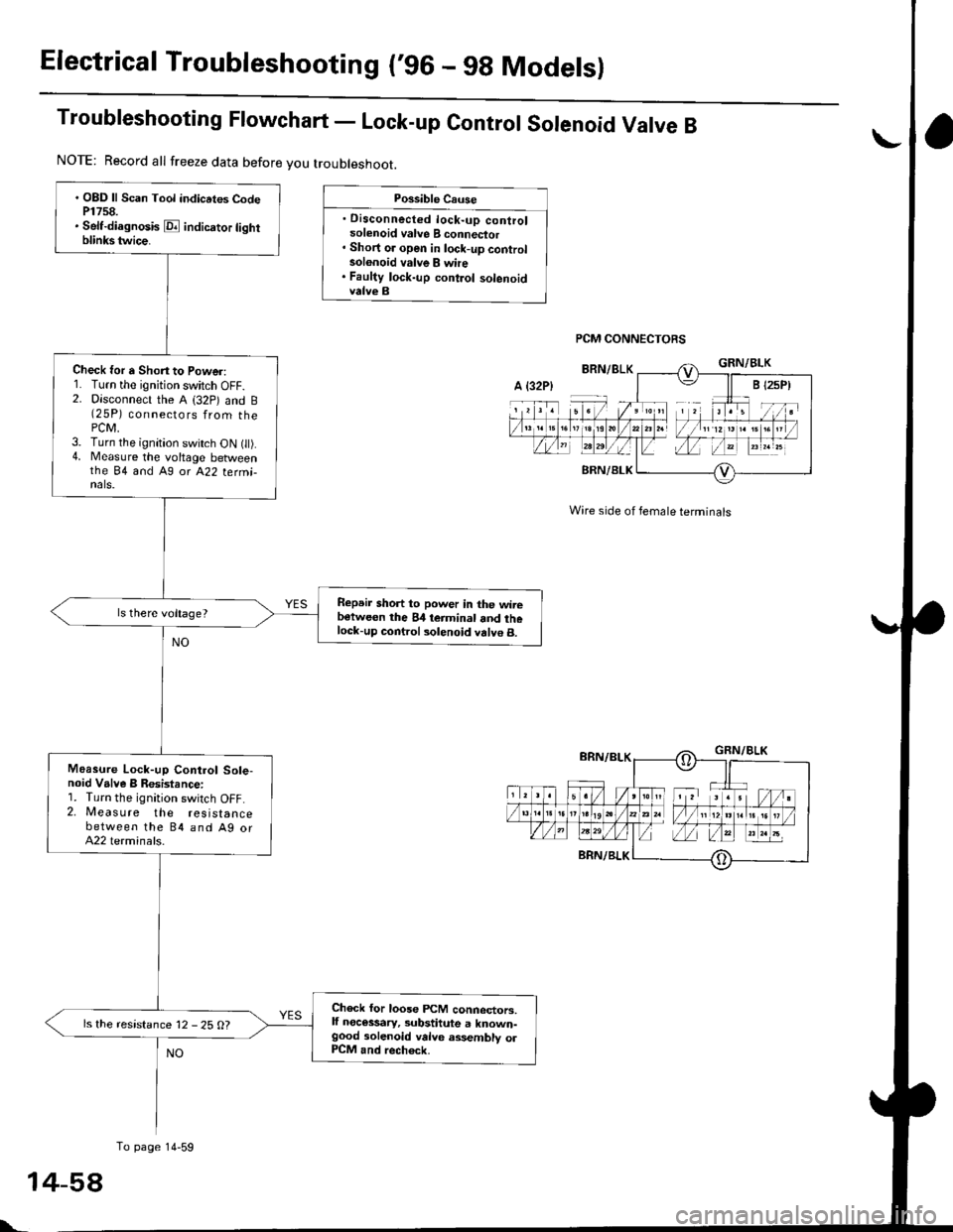
Troubleshooting Ftowchart - Lock-up control sorenoid Varve B
Possible Cause
. Disconnected lock-up controlsolenoid valve B connector' Short or open in lock-up controlsolonoid valve B whe. Faulty lock-up control solenoidvalve B
PCM CONNECTORS
Wire side of female terminals
. OBD ll Scan Tool indicrtes CodeP1758.. Self-diagnosis E indicrtor lightblinkstwice.
Check for a Shon to Power:1. Turn the ignition switch OFF.2. Disconnect the A (32p) and B(25P) connectors from thePCM,3. Turn the ignition switch ON t).4. Measure the voltage betweenthe 84 and A9 or A22 termi-nals.
Repeir short to power in the wirebetween the 84 teiminal and thelock-up control solenoid valve B.
Moasure Lock-up Control Sole-noid Valve B Resistance:1. Turn the ignition switch OFF.2. Measure the resistancebetween the 84 and Ag orA22 terminals.
Check for loose FCM connectors,lf necessary, substitute a known-good solenoid valve assembly olP1CM and rech6ck.
ls the resistance 12 - 25 O?
NOTE: Record all freeze data before you troubleshoot.
A {32P)
To page 14-59
t-
Page 738 of 2189

Electrical Troubleshooting ('96 - 9g Models)
Troubleshooting Flowchart - A/T Gear position Switch (Shortl
NOTE: Record allfreeze data before you troubleshoot.
Poiriblo Caus6
. Short in A/T go.. positionawhch wira. Fauhy A/T goa. position swhch
NOTE: Code P1705 (5)the PCM receives twoinputs at the same time.
is caused whengear position
' OBD ll Scln Toot indic.tes Cod6P1705.. Sofidi.gno3b E indicato] tighrblinksfivatim...
Observo th. A/T Go.r po3ition
Indicator:1. Turn the ignition switch ON l).2. Observe the A"/T gear positionindicator, and shitt to eachposttron,
Do any indicatoG stay onwhen the shift lever is not inthose positions?
Tho sy3tem b OK.t this timo.Check th6 wilc harnari for dam-rga.
M.r.ur. ATP R Vohlge:1. Shift to all positions otherthanE.2. Nileasure the voltage betweenthe 816 and Ag or A22 tormi-nats,
Check for short in tha wirobstwacn the 816 tcrminal and th6A/T go.r porition rwitch or A/Tg..r position indicltor. It wira i3OK, ch.ck for loo!€ FCfit connoc-to13. lf nacetaary, subrtitute aknown€ood Pcllt and roa|rsck.
ls there battery voltage?
Meesur. ATP NP Vohage:1. Shift to allpositions oth€r thanEorE.2. Moasure the voltage betweenthe 825 and A9 or A22 terminats.Check for short in the wireb.tw..n th6 B:I5 torminrt and th.A/T gclr poahion indicator. o. .short in tha wirrs between th.A/T gclr position indicator rndthe A/T gerr poiition switch. lfwir.3 r.o OK, chack tor loosoPCM conn.ctorr. It n.cosarry.sub.tituto a known-good pCM.nd r.chock.M.Gur. ATP D4 Voltago:1. Shift to allpositions otherthanlD.l.2. Measure the voltage betw€enrhe 824 and Ag or A22 termi-nals.
Check tor 3hort in tho wirobc{wocn the 824 terminrl and thoA/T ge.r poiition switch. lI wileia OK, chock tor loo3o plCM con-ncctoaa. It nacossarv, sublthute aknown-good PCM and rech€ck.
ls there approx. 5 V?
PCM CONNECTORS
Wire side of female terminals
YES
To page 14-6':
14-60
Page 740 of 2189

Electrical Troubleshooting ('96 - gg Modelsl
Troubleshooting Flowchart - A/T Gear position Switch (Open)
. OBD ll Scan Tool indicates CodeP1706.. Self-di.gnosk E indicator tightblinks six timos.
Measure ATP 04 Voltege:1. Shiftto E position.2. Measure the voltage betweenthe 824 and A9 or A22 terminals,
ls there voltage?
Possible Causo
. Disconnected A/T gear positionswitch conn€ctor. Open in A/T gear positionswitch wire. Faulty A/T gear position switch
Wire side of female terminals
NOTE: Record all freeze data before you troubleshoot.
Moasure ATP I Voltage:1. Turn the ignition switch ON 1 ).2. Shift to E position.3. Measure the voltage betweenthe B'f6 and Ag ot A22 tetmi-nats.
Ropai. op€n in the wire betwe€nthe Bl6 terminal.nd the A/T gearposition swhch.
Measur€ ATP NP Voltage:1. Shift to E or E position.2. Measure the voltage betweenthe 825 and A9 or A22 termi,nals,
Repeir open in the wir€ betweentho B25 terminal and th6 A/T geerposition indicator or tho A/T 96.rposition 3witch.
Rcpair open in the wire betweentto 82{ to.minal and th6 A/T geatlrosition 3witch.
To page 14 63
PCM CONNECTORS
NO
1
L
+62
Page 742 of 2189

Electrical Troubleshooting ('96 - 98 Modelsl
Troubleshooting Flowchart - Shift Gontrol Solenoid Valve A
Po$ible Cau3e
. Disconnected shift controlsolenoid valve A connector. Short oi open in shift controlsolenoid valve A wire. Faulty shirt control solenoid
PCM CONNECTORS
' OBD ll Scan Tool indicates CodeP0753.. Sett{iagnosis E indicator lightblinks seven tim6.
Check tor a Short to Power:1. Turn the ignition switch OFF.2. Disconnect the A (32P) and B{25 Pi connectors trom thePCM.3. Turn the ignition switch ON {ll).4. Measure the voltage betweenthe 83 and A9 orA22 terminals.
Repair short to powe. in the wir6between the 83 terminal .nd theshift control solonoid valvo A.
Moa3ure Shift Control SolenoidValve A Resistanc€:1. Turn the ignition switch OFF.2, Measure the resistancebetween the 83 and A9 or A22terminals.
Ch€ck for loose PCM connectors.lf n€c6srry, subatitute a known-good solenoid valve a3,sembly orPCM end rocheck.
ls the resistance 12 - 25 0?
NOTE: Record all freeze data before you troubleshoot.
A t32Pl
To page 14-65
Wire side ol female terminals