1996 HONDA CIVIC Throttle body
[x] Cancel search: Throttle bodyPage 465 of 2189
![HONDA CIVIC 1996 6.G Workshop Manual ldle Gontrol System
ldle Air Control (lAG) Valve (99 - 00 Dl6Y8 engine with M/T, Bt6A2 enginel
[Fl50g l ]h" scan tool indicates Diagnostic Trouble Code (DTC) P1508: A problem in the ldle Air Controt HONDA CIVIC 1996 6.G Workshop Manual ldle Gontrol System
ldle Air Control (lAG) Valve (99 - 00 Dl6Y8 engine with M/T, Bt6A2 enginel
[Fl50g l ]h" scan tool indicates Diagnostic Trouble Code (DTC) P1508: A problem in the ldle Air Controt](/manual-img/13/6068/w960_6068-464.png)
ldle Gontrol System
ldle Air Control (lAG) Valve ('99 - 00 Dl6Y8 engine with M/T, Bt6A2 enginel
[Fl50g l ]h" scan tool indicates Diagnostic Trouble Code (DTC) P1508: A problem in the ldle Air Controt AC) vatve- CtrCUtt.
The IAC Valve changes the amount of air bypassing the throttle body in response to a current signal from the ECM inorder to maintain the proper idle speed.
IAC VALVE 2P CONNECTOR IC138'
la rcprI - {YEL/8LKI 2t--d,
Y-=
Wire side ot female terminals
Wire side of lemale terminals
VALVE
The MIL has boon r€oorted on.DTC P1508 is srored.
Probl6m verification:1. Do the ECM/PCM Reset Pro-cedure.2. Start the engine, and warm itup to normal operating lem-perature.
Intermittent tailure, system is OKat this timg. Check to. poor con-noctions or loose wires at C138{lAC valvel and ECM.
ls DTC P1508 indicated?
Ch6ck for an open in the wir€{lGPl lino}:1. Turn the ignition switch OFF.2. Disconnect the IAC valve 2Pconnector.3. Turn the ignition switch ON (ll).
4. Measure voltage between bodyground and the IAC valve 2Pconneclor termina I No.2,
Repair opon in the wire bgtwoenIAC valve and PGM-Fl main relay.
Check tof an open or short in thewire {IACV line}l1. Turn the ignition switch OFFand reconnect the IAC valve
2. Disconnect the ECM connectorB {25P).3. Turn the ignition switch ON (ll).
4. Measure voltage betweenbody ground and ECM conn€ctor terminal 823.
(To page 11-197)
1 1-1 96
Page 467 of 2189
ldle Control System
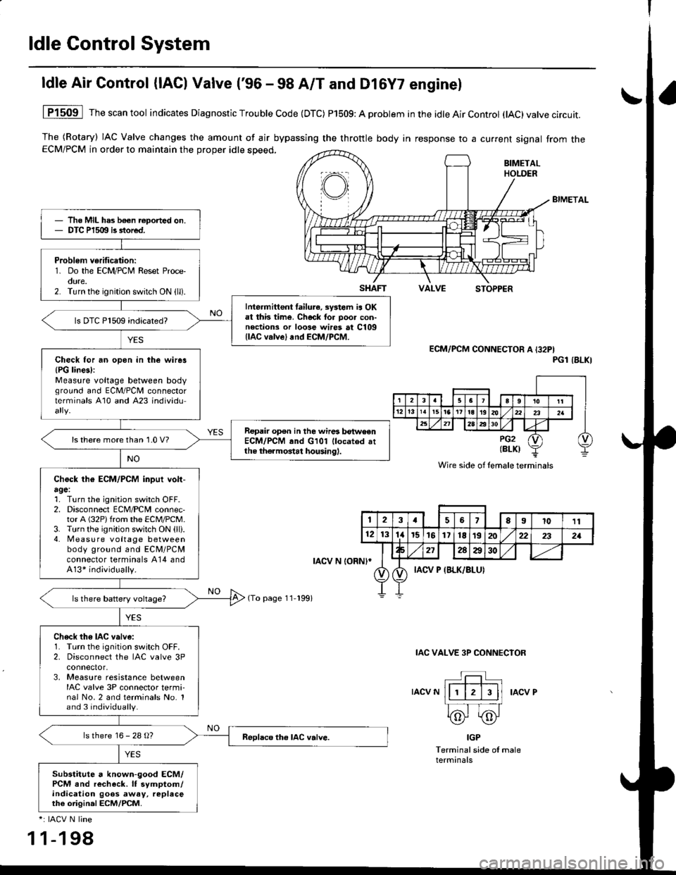
ldle Air Control (lAC) Valve ('96 - 98 A/T and Dl6Y7 enginel
The (Rotary) IAC Valve changes the amount of air bypassing the throttle body in response to a current signal from theECM/PCM in order to maintain the proper idle speed,
BIMETAL
VALVESTOPPER
1P1509 Thescantool indicates Diagnostic Trouble Code (DTC) P1509: A problem in the idle Air Control (tAC)valve circuit.
ECM/PCM CONNECTOR A I32PIPGl IBLKI
IAC VALVE 3P CONNECIOR
IACV NIACV P
IGP
Terminal side of maleterminals
*: IACV N line
1 1-198
The MIL has b€€n roported on.DTC P1509 is stored.
Problem verification:1. Do the ECM/PCM Reset Proce-oure.2. Turn the ignition switch ON (ll).
Intermittent failura, systom ia OKat this time. Check tor poo. con-noctions or loose wires at C109llAC valve) and ECM/PCM.
ls DTC P1509 indicated?
Check for an opon in the wirer{PG lines):Measure voltage between bodvground and ECM/PCII connectorterminals A10 and A23 individu
Repair op€n in the wires betwoenECM/PCM and G101 llocated attho thermostat housing).
ls there more than 1.0 V?
Chock th€ ECM/PCM inpui volt-agel1. Turn the ignition switch OFF.2. Disconnect ECM/PCM connec-tor A (32P)from the ECM/PCM.3. Turn the ignition switch ON (ll).4. Measu re voltage betweenbody ground and ECM/PCMconnector terminals A14 andA13* individually.
Ch6ck th6 IAC valve:1. Turn the ignition switch OFF.2. Disconnect the IAC valve 3Pconnector,3, Measure resistance betweenIAC valve 3P connector termi-nal No.2 and terminals No. 1and 3 individually.
ls there 16 - 28 g?
Substitute a known-good ECM/PCM and recheck. lf symptom/indication goos away, replaceth€ origin.l ECM/PCM.
SHAFT
rAcv N loRNl*
(To page 11-199)
Wire side of lemale terminals
123a56El011
121314r5161718t9202:22321
272AA30
IACV P {BLK/BLUI
Page 469 of 2189
ldle Gontrol System
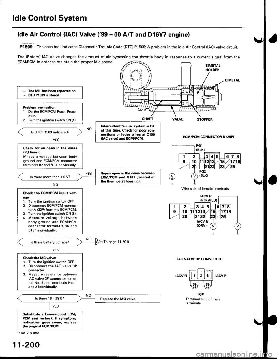
The (Rotary) IAC Valve changes the amount of air bypassing the throttle body in response to a current signal from the
ECM/PCM in order to maintain the proper idle speed.BIMETALHOLDER
BIMETAL
SHAFTVALVESTOPPER
ECM/PCM CONNECTOR B {25P}
(To page 11-201)
IAC VALVE 3P CONNECTOR
IACV NIACV P
ldle Air Control {lACl Valve ('99 - 00 A/T and Dl6Y7 enginel
YES
1P1509 lThescantool indicates Diagnostic Trouble Code (DTC) P1509:A problem inthe idleAirControl (lAC)valve circuit.
IGP
Terminal side of maleterminals
Sub3titute e known-good ECM/PCM .nd recheck. lf 3vmptom/indicalion goos away, replac6thc original ECM/PCM.
*: IACV N line
11-200
Tho MIL has b€en reported on.OTC P1509 is sto.ed.
Problem verilicationr1. Do the ECM/PCM Reset Proce-dure.2. Turn the ignition switch ON (ll).
Intermittont tailure, sy3tem i3 OKat thb time. Check for poor con'noctions or loose wiros at C109(lAC velvel and ECM/PCM.
ls DTC P1509 indicated?
Check for an oDen in the wilosIPG linesl:Measure voltage between bodyground and ECM/PCM connectorterminals 82 and 810 individually.
Ropail open in the wires be'tw€enECM/PCM .nd G101 llocated .tthe the.mostat housingl.ls there more than 1.0 V?
Check tho ECM/PCM input volt-age:1. Turn the ignition switch OFF.2. Disconnect ECM/PCM connec-tor A (32P)trom the ECM/PCM.3. Turn the ignition switch ON (ll).
4, Measure voltage betweenbody ground and ECM/PCMconnector terminals 86 and815* individually.
Chock the IAC v.lve:1. Turn the ignition sw;tch OFF.2. Disconnect the IAC valve 3Pconnoctor.3. Measure resistance betweenIAC valve 3P connector termi'nal No. 2 and terminals No. 1and 3 individually.
ls there 16 - 28 O?
Wire side of female terminals
Page 516 of 2189

IThrottle BodY
Description
The throttle bodY is either a single-barrel side-draft type
(D16Y5, D16Y8, 816A2 engine) or a down-draft type
(D16Y/ engine). The lower portion ot the throttle valve is
heated by engine coolant from the cylinder head' The
idle adjusting screw which regulates the bypass air is
located on the top of the throttle body
THROTTLEPOS|T|ON lTPlSENSOR
IDLE AD.'USTINGSCREW
t
In3pection
1. Check that the throttle cable operates smoothly
without binding or sticking.
lf there are any abnormalities, check for:
. Excessive wear or play in the throttle valve shaft'
. StickY or binding throttle lever at the fully closed
Position.. Clearance between throttle stop screw and throt-
tle lever at the fully closed position'
D16Y5, Dl6Y8 engine:
THROTTLE STOP SCREW
{Do not adjust.)
Dl6Y7 ongine:
816A2 engins:
THROTTLE LINK
STOP SCREW
THROTTTE STOP SCREW(Do not adjust.)
Replace the throftle body if thsre is excessive play in the
throttle valve shaft or iJ the shaft is binding or sticking'
(cont'd)
11-247
{Do not adjust.)
Page 517 of 2189
Intake Air System
J
Throttle Body (cont'dl
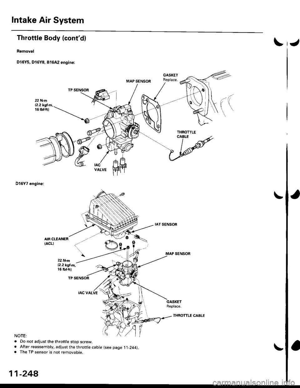
Removal
D16Y5, Dl6Y8, 81642 engine:
D15Y7 engine:
AIR CLEANER
{ACLI
22 N.m12.2 kgl.m,16 rbf.ftl
NOTE:
. Do not adjust the throttle stop screw.. After reassembly, adjust the throttle cable {see page l l-244).. The TP sensor is not removable.
IAT SENSOR
MAP SENSOR
GASKETReplace.
11-248
THROTTLE CABLE
Page 552 of 2189

\
t,96 D16Y8 engine (coup6l,'9? Dl6Y7 engine (coupe: KL model, sedan: KL (LX) model)"g7 Dl6Y8 ongine (coupe: all mod-
els, sedan: KL model,'98-8ll modelsl 39 - 00 Dl5Y5 engine with M/Tl:
The scan tool indicates Diagnostic Trouble code (DTc) P1456: Evaporative Emission (EVAP) control system leak
detected (fuel tank sYsteml
The scan tool indicates Diagnostic Trouble Code (DTC) P1457: Evaporative Emission (EVAP) control system leak
detected (EVAP control canister system).
Fr4t6l
fF14s7
Possible Causs
. Fuel fill cap
. Vacuum Connections
. Fuel Tank
. EVAP Control Canister Vent Shut Valve
. EVAP Control Canister Vent Shut Valve Circuit
. EVAP Purge Control Solenoid Valve
. EVAP Purge Control Solenoid Valve Circuit
. EVAP Bypass Solenoid Valve
. EVAP Bypass Solenoid Valve Circuit
. Fuel Tank Pressure Sensor
. Fuel Tank Pressure Sensor Circuit
. EVAP Control Canister
. Throttle Body
Troublsshooting Flowchart
VACUUMPUMP/GAUGE,0 - 30 in.HgA973X - 041 -
xxxxx
I
EVAPCONTROL
.4, cANrsrER
re ./ VALVE
{S----r*::n
\(cont'd)
- The MIL ha3 been rePofted
on.- DTC P1456 or P1457 is stored.
Check the EVAP control canbtol
vent shut valve:1. Disconnect the vacuum hose
Irom the EVAP three waY
valve and connect a vacuurnpump to the hose.
2. Remove the EVAP control
canister vent shut valve Irofi
the canrster.3. Turn the ignition switch ON (lli
4. Apply vacuum to the hose.
Chock for . shon in the wire(VSv linel:Disconnect the 2P connector {rom
the EVAP control canister vent
Does the valve hold vacuum?
Repair short in the wir€ betwcen
the EVAP control canister vent
shut v.lve and tho ECM/PCM
tA29|.
Does the valve hold vacuum?
Check the EVAP control canister
vent shui valve:1. Turn the ignition switch OFF.
2. Connect ECM/PCM connectorterminal A29 to body ground
with a iumPer wire.
3. Turn the ignition switch ON (ll).
4. Applyvacuum to the hose
Reohce the EVAP control canis-
ter vent shttt valve.
Does the valve hold vacuum?
ECM/PCM CONNECTOR A {32P)
37I9t01t't2t3t5t6ItItt9202a2a
25aA
ILT GRN/W{T) I JUMPER WIRE
Wire side of femll terminals
(To page 11-284i(To page 11 284)
11-283
Page 557 of 2189
Emission Control System
Evaporative Emission {EVAP) Controls (cont'dl
\J
tF1456-l
tP14sz-l
EVAPCONTROLCANISTERVENTSHUTVALVE
O.RINGReplace.
EVAPCONTROLCANISTER
ECM/PCM CONNECTOR A I32PI
(To page 11'289)
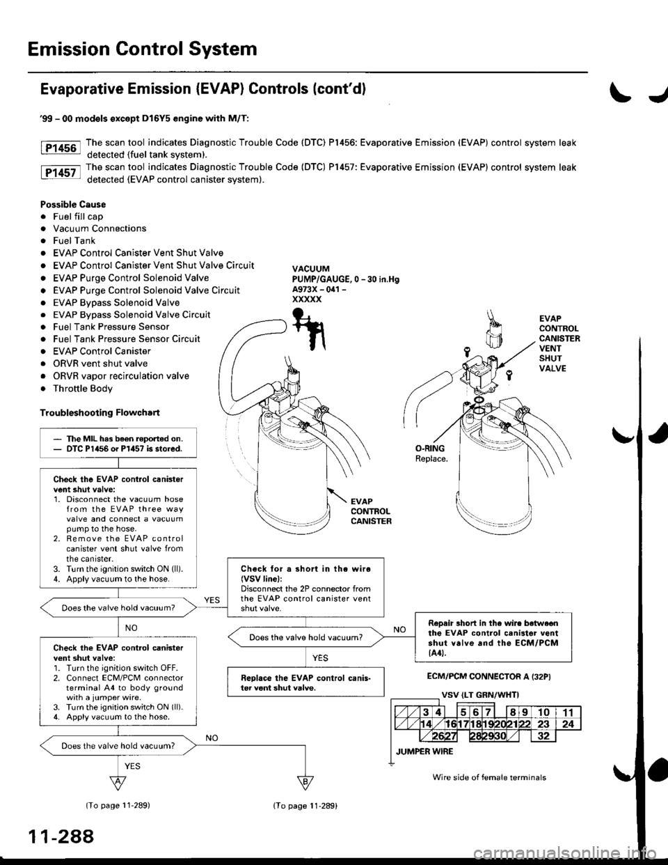
'99 - 00 modols except Dl6Y5 engine with M/T:
The scan tool indicates Diagnostic Trouble Code (DTC) P1456: Evaporative Emission (EVAP) control system leak
detected (fuel tank svstem).
The scan tool indicates Diagnostic Trouble Code (DTC) P1457: Evaporative Emission (EVAP) control system leak
detected (EVAP control canister system).
Possible Cause
. Fuel fill cap
. Vacuum Connections
. FuelTank
. EVAP Control Canister Vent Shut Valve
. EVAP Control Canister Vent Shut Valve Circuit
. EVAP Purge Control Solenoid Valve
o EVAP Purge Control Solenoid Valve Circuit
. EVAP Bypass Solenoid Valve
0 -30 in,Hg
. EVAP Bypass Solenoid Valve Circuit
. Fuel Tank Pressure Sensor
. Fuel Tank Pressure Sensor Circuir
. EVAP Control Canister
. ORVR vent shut valve
. ORVR vapor recirculation valve
. Throttle Body
Troubleshooting Flowchart
VACUUMPUMP/GAUGE,A973X - oal -
xxxxx
T-t
t\
The MIL has been reported on.DTC P1456 o. P1457 is stored.
Check the EVAP cont.ol canistervent shul valve:1. Disconnect the vacuum hosefrom the EVAP three wayvalve and connect a vacuumpump to the hose.2. Remove the EVAP controlcanister vent shut valve fromtne canrster.3. Turn the ignition switch ON (ll).
4. Apply vacuum to the hose.Check for a short in the wiro(VSV linel:Disconnect the 2P connector fromthe EVAP control canister ventDoes the vaive hold vacuum?
RoDair 3hort in the wire botwe€nthe EVAP control canilter ventshut valve and the ECM/PCM{A4t.
Does the valve hold vacuum?Check the EVAP cont.ol canisterv€nl shut valve:1. Turn the ignition switch OFF.2. Connect ECM/PCM connectorterminal A4 to body groundwith a jumper wire.3. Turn the ignition switch ON (ll).
4. Apply vacuum to the hose.
Reolace the EVAP control canis-ter veni shut valve.
Does the valve hold vacuum?
Wire side of female terminals
11-288
lTo page 11-289)
Page 888 of 2189
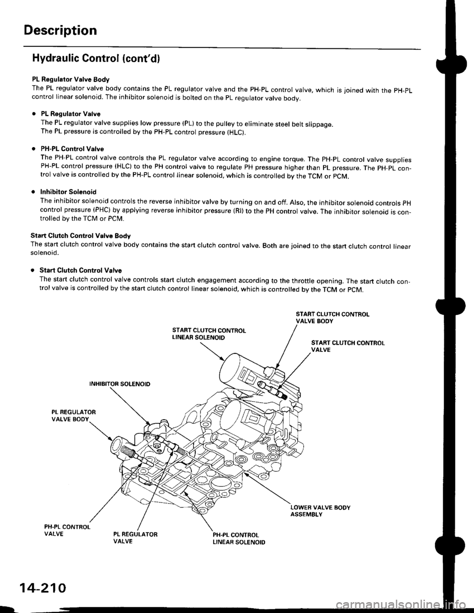
Description
Hydraulic Control {cont'dl
PL Regulator Valve Body
The PL regulator valve body contains the PL regulator valve and the PH-PL control valve. which is joined wirh the pH-pL
control linear solenoid. The inhibitor solenoid is bolted on the pL regulator valve body.
. PL Regulator Valve
The PL regulator valve supplies low p.essure (pL) to the pulley to eliminate steel belt slippage.The PL pressure is controlled by the pH-pL control pressure (HLC).
. PH-PL Control Valve
The PH-PL control valve controls the PL regulator valve according to engine torque. The PH-PL control valve suooliesPH-PL control pressure (HLC) to the PH control valve to regulate PH pressure higher than pL pressure. The pH-pL con-trol valve is controlled by the PH-PL control linear solenoid. which is controlled by the TcM or pcM,
. Inhibitor Solenoid
The inhibitor solenoid controls the reverse inhibitor valve by turning on and off. Also, the inhibitor solenoad controls pH
control pressure (PHC) by applying reverse inhibitor pressure (Rl) to the PH control valve. The inhibitor solenoid is con-trolled by the TCM or Pclvl.
Start Clutch Control Valv€ Body
The start clutch control valve body contains the start clutch control valve. Both are joined to the stan clutch control linearsolenoid.
. Start Clutch Control Valve
The start clutch control valve controls start clutch engagement according to the throttle opening. The start clutch con,trol valve is controlled by the stan clutch control linear solenoid, which is controlled bv the TCM o. pCM.
START CLUTCH CONTROLvAt-vE
LOWER VALVE BODYASSEMBI-Y
PH.PL CONTROLLINEAR SOLENOID
I.
14-210