Page 1964 of 2189

Rear Window Defogger
- How the Circuit Works
'96198 Models
Voltage is applied at all limes through tuse 50 to the
rear window detogger relay (contacts). With the
ignition switch in ON (ll), voltage is applied through
tuse 16 to the rear window defogger switch.
When you turn the switch ON, voltage is applied to
the defogger timer circuit. The timer circuit supplies
voltage to the rear window defogger relay (coil). The
relay energizes and supplies voltage to the rear
window defogger. The defogger grid then heats the
rear window to remove any condensation from the
glass.
The defogger timer circuit will automatically turn off
the rear window defogger after about 25 minutes.
Refer to the Service Manual (Section 23, Electrical)
for specific tests or troubleshooting procedures.
'99100 Models
Voltage is applied at all times through fuse 50 to the
rear window delogger relay (contacts). With lhe
ignition switch in ON (ll), voltage is applied through
fuse 16 to the heater control oanel.
When you turn the rear window defogger switch
ON, a signal is sent to lhe defogger timer circuit
built-into the heater control oanel. The timer circuit
supplies voltage to the rear window defogger relay
(coil). The relay energizes and supplies voltage to
the rear window defogger. The defogger grid then
heats the rear window to remove anv condensation
from the glass.
The defogger timer circuit will automatically turn otf
the rear window defogger after about 25 minutes.
Refer to the Seryice Manual (Section 23, Electrical)
for specific tesls or troubleshooting procedures.
64-2
I
a
a
Page 2120 of 2189

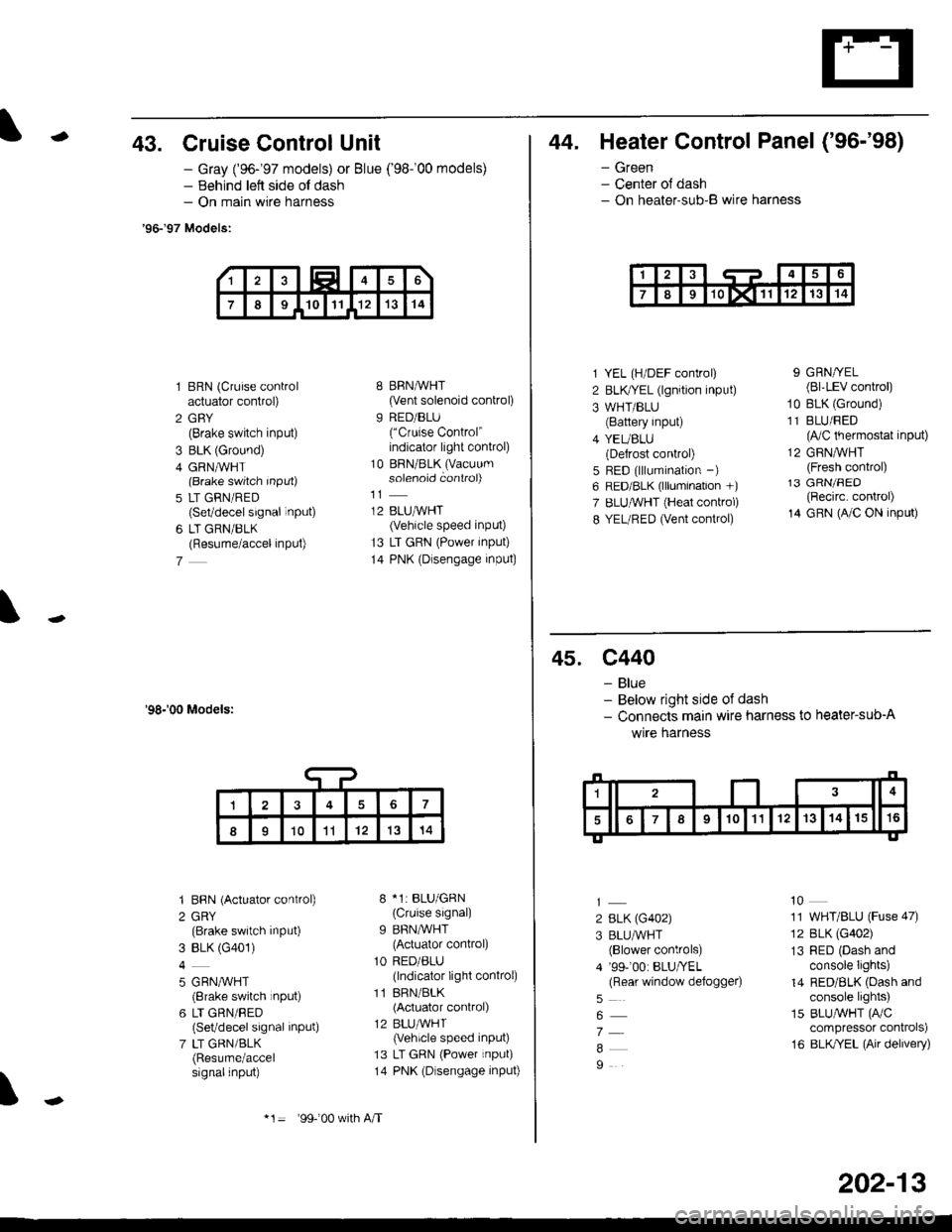
-43. Cruise Control Unit
- Gray ('96-'97 models) or Blue ('98-'00 models)- Behind lett side ol dash- On main wire harness
'96-'97 Models:
1 BRN (Cruise controlactuator control)
2 GBY(Brake switch input)
3 BLK (Ground)
4 GRN,ryVHT(Brake switch Input)
5 LT GRN/RED(Set/decel signal inPUt)
6 LT GRN/BLK(Resume/accel inPut)
7
'98-'00 Models:
'I BBN (Actuator control)
2 GRY(Brake switch input)
3 BLK (G401)
4
5 GRN,^/VHT(8rake switch rnput)
6 LT GRN/RED(Set/decel signal inPut)
7 LT GRN/BLK(Resume/accelsignalinput)
8 BRN,AiVHT(Vent solenoid control)
9 RED/BLU("Cruise Control"indicator light conkol)
10 BRN/BLK (Vacuum
solenoid controi)
12 BLUMHT(Vehicle speed input)
13 LT GRN (Power input)
14 PNK (Dlsengage input)
8 *1: BLU/GRN(Cruise signal)
9 BFN/WHT
{Actuator control)
1O RED/ALU(lndicator light conkol)
11 BRN/BLK(Actuator control)
12 BLU,ryVHT(Vehicle speed input)
13 LT GRN (Power input)
14 PNK (Dlsengage input)
\
17
II1011'121314
*1= 99-'00 w(h A/T
202-13
44. Heater Control Panel ('96-'98)
- Green- Center ol dash- On heater-sub-B wire harness
1 YEL (H/DEF control)
2 BLKTYEL (lgnition input)
3 WHT/BLU(Battery input)
4 YEUBLU(Defrost control)
5 RED (lllumination -)
6 RED/BLK (lllumination +)
7 ELUruVHT (Heat conkol)
8 YEL/RED (Vent control)
9 GRN/YEL(Bl'LEV control)
10 BLK (Ground)
11 BLU/FED(lVC thermostat input)
12 GRNMHT(Fresh control)13 GRN/FED(Recirc. control)
14 GRN (A/C ON input)
45. c440
- Blue- Below right side of dash- Connects main wire harness to heater-sub-A
wrre narness
2 BLK (G402)
3 BLU/WHT(Blower controls)
4 '99-'00: BLU/YEL(Rear window defoggeo
7
9
10
11 WHT/BLU (Fuse 47)
12 BLK (G402)
13 RED (Dash andconsole Iights)
14 RED/BLK (Dash andconsole lights)
15 BLUAVHT (FVC
compressor conkols)
16 BLK/YEL (Air delivery)
Page 2140 of 2189

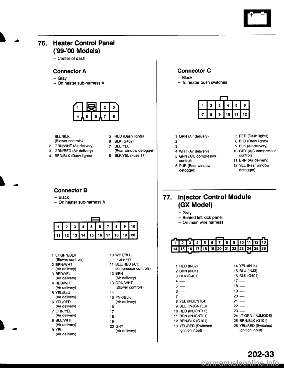
76. Heater Control Panel
('99100 Models)
- Center of dash
Conneclor A
- Gray- On heater sub-harness A
BLUi BLK(Blower controls)
GRNAVHT (Air delivery)
GRN/RED (Air delivery)
RED/BLK (Dash lights)
Connector B
- Black- On heater sub-harness A
7
8
1
4
RED (Dash lights)
BLK (G402)
BLUfYEL(Rear window defogg€0
BLK,TYEL (Fuse 17)
\
)
1 LT GRN/BLK(Blower controls)
2 BRN,A/VHT(Air delivery)
(Air delivery)
4 REDA/VHT(Air delivery)
5 YEUBLU(Air delivery)
6 YEURED(Air delivery)
7 GRN/YEL(Air delivery)
8 BLU,ryVHT(Air delivery)
9 YEL
{Air delivery)
1O WHT/BLU(Fuse 47)
11 BLU/RED WCcompressor controls)
12 BRN(Air delivery)
13 ORNAVHT(Blower controls)
14 -
15 PN(BLK(Air delivery)
16 _
19 _
20 GRY(Air delivery)
Connector C
- Black- To heater push switches
1 ORN (Air delivery)
2
4 WHT (Air delivery)
5 GRN (ry'C compressorcontrol)
6 PUR (Roar windowdelogge4
7 RED (Dash lights)
8 BLU (Dash lights)
I BLK (Air delivery)
10 GRY (Ay'C compressorcontrols)
1'1 BRN (Air delivery)
12 YEL (Rear window
defogge0
77. Injector control Module
(GX Model)
- Gray- Behind left kick panel- On main wire harness
1 RED (rNJ2)
2 BRN (rNJl )3 BLK (G401)
4_
8 YEL (TNJCNTL4)
9 BLU (TNJCNTL3)
1o RED (tNJCNTL2)
11 BRN 0NJCNTL1)12 BRN/BLK (G101)
13 YEURED (Switched
ignition input)
14 YEL (tNJ4)
15 BLU (rNJ3)
16 BLK (G401)
19 -
20-
21
24 LI GRN (INJMODE)
25 BRN/BLK (Gr 01)
26 YEURED (Switched
ignition input)
202-33
Page:
< prev 1-8 9-16 17-24