1996 HONDA CIVIC Measurements
[x] Cancel search: MeasurementsPage 668 of 2189

Mainshaft Thrust Clearance
Adjustment
1. Remove the 72 mm thrust shim and oil guide platefrom the transmission housing.
4.
TFANSMISSIONHOUSING
72 mm THRUST SH|M
TRAt{SMtSStONHOUSINGOIL GUIOE PLATE
lnstall the 3rd/4th synchro hub. spacer collar,5thsynchro hub. spacer, and ball bearing on the main_shaft, then install the above assembly in the trans_mission housing.
lnstall the washe[ on the mainshaft,
Measure distance @ between the end of the trans-mission housing and washer.
NOTE;
. Use a straight edge and vernier caliper.. Measure at three locations and average the read_ing.ENO otlnA sMtsstoNHOUSINGMAINSHAFT
3RD/irTH SYNCHRO HUB
SPACCR COLLAR
5TH SYNCHRO HUB
o
B
13-88
AALL BEARING
V.
5. Measure distance @ between the end of the clutchhousing and bearing inner race.
NOTE;
. Use a straight edge and depth gauge.. Measure at three locations and average the read-ings.
Select the prcpet 72 mm thrust shim from the chartby using the formula below.
NOTE: Us€ only one 72 mm thrust sntm.
Shim Selection Formula:
From the measurements you made in steps 4 and 5:. Add distance O lstep 5) to distance @ (step 4).
. From this number, subtract 0.93 (which is themidpoint of the flex range of the clutch housingbearing spring washer).
. Take this number and compare it to the availableshim sizes in the chart.
{For example)
B;2.39
+ C: 0.22- 0.93
2.61 = 1.68
Try the 1.68 mm (0.0661 in) shim.
INNER RACE ot EALL BEARING
Page 798 of 2189

Pressure Testing
(cont'd)
Line Pressure/1st Clutch Pressurc Measurement
1. Set the parking brake, and btock both rear wheels securely.
2. Start the engine, and run it at 2,OOO rpm.
3. Shift to N or E position, then measure line pressure.
NoTE: Higher pressure may be indicated if measurements are made in shift lever positions other than @ or @ positron.
4. Shift to tq;l position, hold the engine at 2,000 rpm, and measure 1st crutch pressure.
1ST CLUTCH PRESSUREINSPECTION HOLE(Marked with "1")
LOCK.UP CONTROLSOLENOID VALVE A/8ASSEMBLY
VALVE A/B ASSEMBLY
PRESSURESHIFT LEVER
POS|TtONSYMPTOMPROBABLE CAUSEFLUID PRESSURE
StandardService Limit
LineN orENo (or low)
lrne pressureTorque converter,
ATF pump, pres-
sure regutator.
torque converter
check valve
830 - 880 kPa
{8.5 - 9.0 kgf/cm?,
120 - 130 psi)
780 kPa(8.0 kgf/cm'�, 110 psi)
1st ClutchD;lNo or low 1st
pressure
1st Clutch
\
14-120
Page 827 of 2189

Inspection
a Clearance Measurement
NOTE: Lubricate all parts with ATF during assembly.
1, Remove the mainshaft bearing from the transmis-
sion housing (see Page 14-1741.
2. Assemble ths parts below on the mainshaft.
NOTE: Do not assemble the O-rings during inspec-
tlon.
LOCKNUTCONICAL SPRIIIG WASHER
SNAP RING
lST CLUTCH ASSEMBLY
TXRUST WASHER
1ST GEAR COLLAR
TRA SMISSIONHOUSII{G BEARING
THRUST WASHER
4TI{ GEAR COLLAR
2ND/4TH CLUTCHASSEMBLY
THRUST WASHER36.5 x 55 mmSelective part.
THBUST NEEDLEBEARING
2ND GEAR
AEABII{G
IHRUST NEEDLEBEARING
MAINSHAFT
3. Torque the mainshaft locknut to 29 N'm (3.0 kgf'm,
22 tbt,ftl.
NOTE: Mainshaft locknut has left-hand threads.
29 N'm t3.0 kgl'm, 22 lbt'ft)
Hold 2nd gear against the 2nd clutch' then measure
the clearance between 2nd gear and 3rd gear with a
feeler gauge.
NOTE: Take measurements in at least three places,
and use the av€rage as the actual clearance'
STANDARD: 0.05 - 0.13 mm 10.002 - 0.005 in)
THRUST WASHER,36.5 x 55 mm
(cont'd)
1+149
Page 832 of 2189
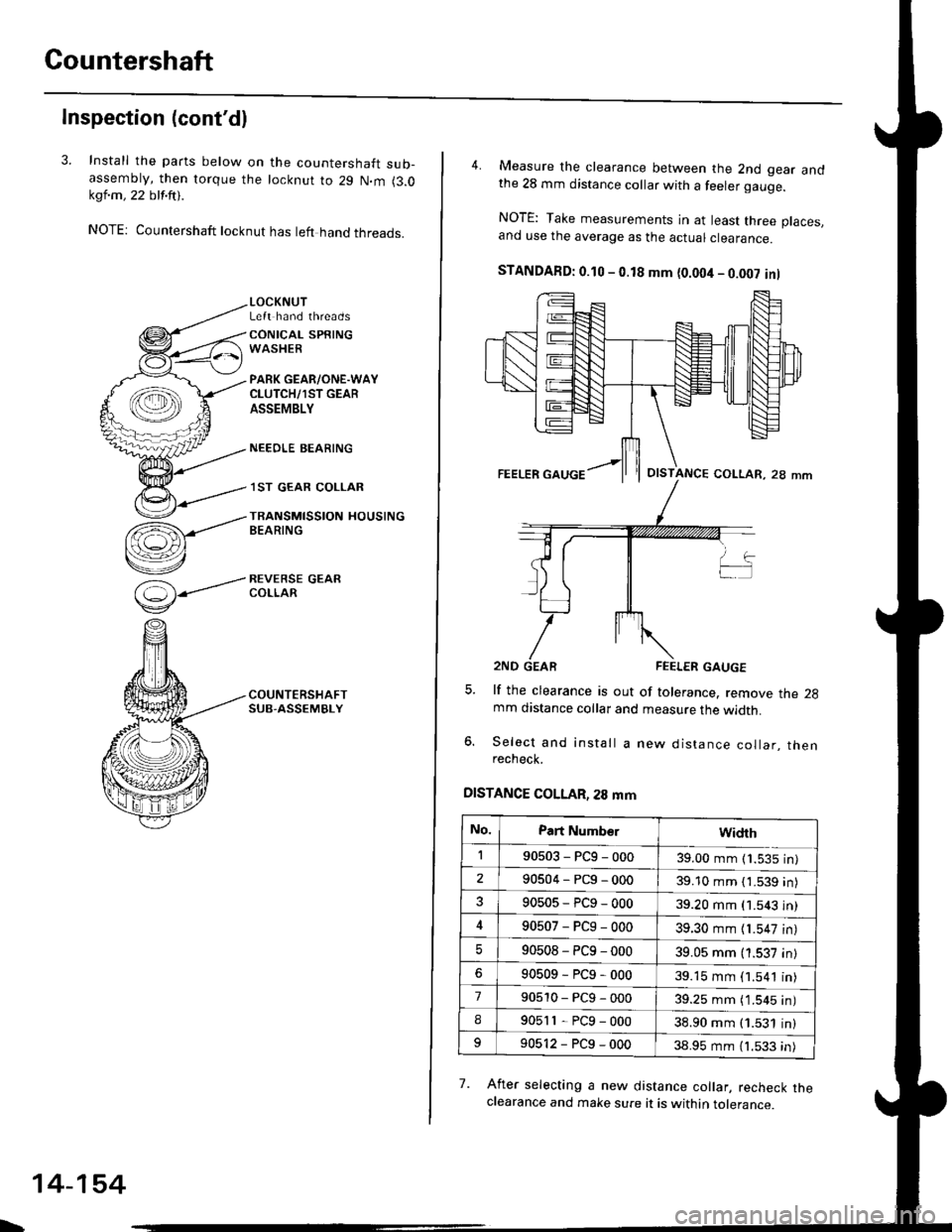
Gountershaft
Inspection (cont'dl
3. Install the parts below on the countershaft sub-assembty, then torque the locknut to 29 N.m (3.0kql.m , 22 blf.ftt .
NOTE: Countershaft locknut has left hand threads.
(=)-----'
v
LOCKNUTLeft hand threads
CONICAL SPRINGWASHER
PARK GEAR/ONE.WAYCLUTCH/1ST GEARASSEMBLY
NEEOLE BEARING
.I ST GEAR COLLAR
TRANSMISSION HOUSINGBEARING
REVERSE GEARCOLLAR
\
14-154
4. Measure the clearance between the 2nd gear andthe 28 mm distance collar with a feeler gauge.
NOTE: Take measurements in at least three places.and use the average as the actuar ctearance.
STANDAFD: 0.10 - 0.18 mm {0.004 - 0.002 inl
lf the clearance is out of tolerance. remove the 2gmm distance collar and measure the width.
Select and install a new distance collar, thenrecheck.
DISTANCE COLLAR, 28 mm
7. Afret selecting a new distance collar, recheck theclearance and make sure it is within tolerance.
OISTANCE COLLAR, 28 mm
No.Part Numb€rwidrh
190503-PCg-00039.00 mm (1.535 in)
290504-PCg-00039.10 mm { 1.539 in)
90505-PCg-00039.20 mm (1.543 in)
90507-PCg-00039.30 mm {1.547 in)
90508-PC9-00039.05 mm (1.537 in)
90509-PCg-00039.15 mm (1.541 in)
790510-PCg-00039.25 mm ( 1.545 in)
I90511-PCg-00038.90 mm (1.531 in)
90512-PCg-00038.95 mm (1.533 in)
Page 843 of 2189
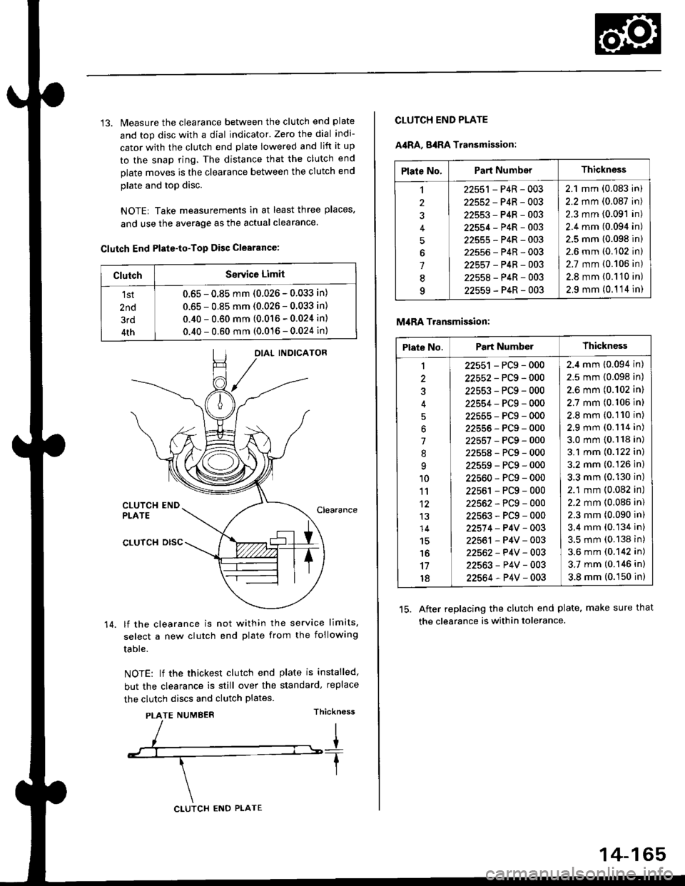
13. Measure the clearance between the clutch end plate
and top disc with a dial indicator' Zero the dial indi-
cator with the clutch end plate lowered and lift it up
to the snap ring. The distance that the clutch end
plate moves is the clearance between the clutch end
plate and top disc.
NOTE| Take measurements in at least three places,
and use the average as the actual clearance.
Clutch End Plste-to-Top Disc Clearance:
OIAL INDICATOR
CLUTCH ENDPLATEClearance
14.
CLUTCH DISC
lf the clearance is not within the service limits,
select a new clutch end plate from the following
table.
NOTE: lf the thickest clutch end plate is installed,
but the clearance is still over the standard, replace
the clutch discs and clutch plates.
PLATE NUMBERThickn6ss
ClutchSerYice Limit
1st
2nd
3rd
4th
0.65 - 0.85 mm (0.026 - 0.033 in)
0.65 - 0.85 mm (0.026 - 0.033 in)
0.40 - 0.60 mm (0.016 - 0.024 in)
0.40 - 0.60 mm (0.016 - 0.024 in)
CLUTCH ENO PLATE
14-165
Plate No.Part NumberThickness
,l
2
J
4
5
6
1
8q
22551 - P4R - 003
22552-P4R-003
22553-P4R-003
22554-P4R-003
22555-P4R-003
22556-P4R-003
22557 -P4B-OO3
22558-P4R-003
22559-P4R-003
2.1 mm (0.083 in)
2.2 mm (0.087 in)
2.3 mm (0.091 in)
2.4 mm (0.094 in)
2.5 mm (0.098 in)
2.6 mm (0.102 in)
2.7 mm {0.106 in)
2.8 mm {0.110 in)
2,9 mm (0.1 '14 in)
CLUTCH END PLATE
A4RA, g4RA Transmission:
M,IRA Transmi$ion:
15. After replacing the clutch end plate. make sure that
the clearance is within tolerance.
Plate No.Part NumberThickness
1
3
'l
.'q
10
11't2
13
14
15'16
17
18
22551 - PCg - 000
22552-PCg-000
22553-PCg-000
22554-PCg-000
22555-PCg-000
22555-PCg-000
22557-PCg-000
22558-PCg-000
22559-PCg-000
22560-PCg-000
22561 - PCg - 000
22562-PCg-000
22563-PCg-000
22574 - P4V - 003
22561 - P4V - 003
22562- P4V - 003
22563-P4V-003
22564-P4V-003
2.4 mm (0.094 in)
2.5 mm (0.098 in)
2.6 mm {0.102 in)
2.7 mm (0.106 in)
2.8 mm (0.110 in)
2.9 mm (0.114 in)
3.0 mm {0.118 in)
3.1 mm (0.122 in)
3.2 mm (0.126 in)
3.3 mm (0.130 in)
2.1 mm (0.082 in)
2.2 mm {0.086 in)
2.3 mm (0.090 in)
3.4 mm (0.134 in)
3.5 mm (0.138 in)
3.6 mm (0.142 in)
3.7 mm (0.146 in)
3.8 mm (0.150 in)
Page 1004 of 2189
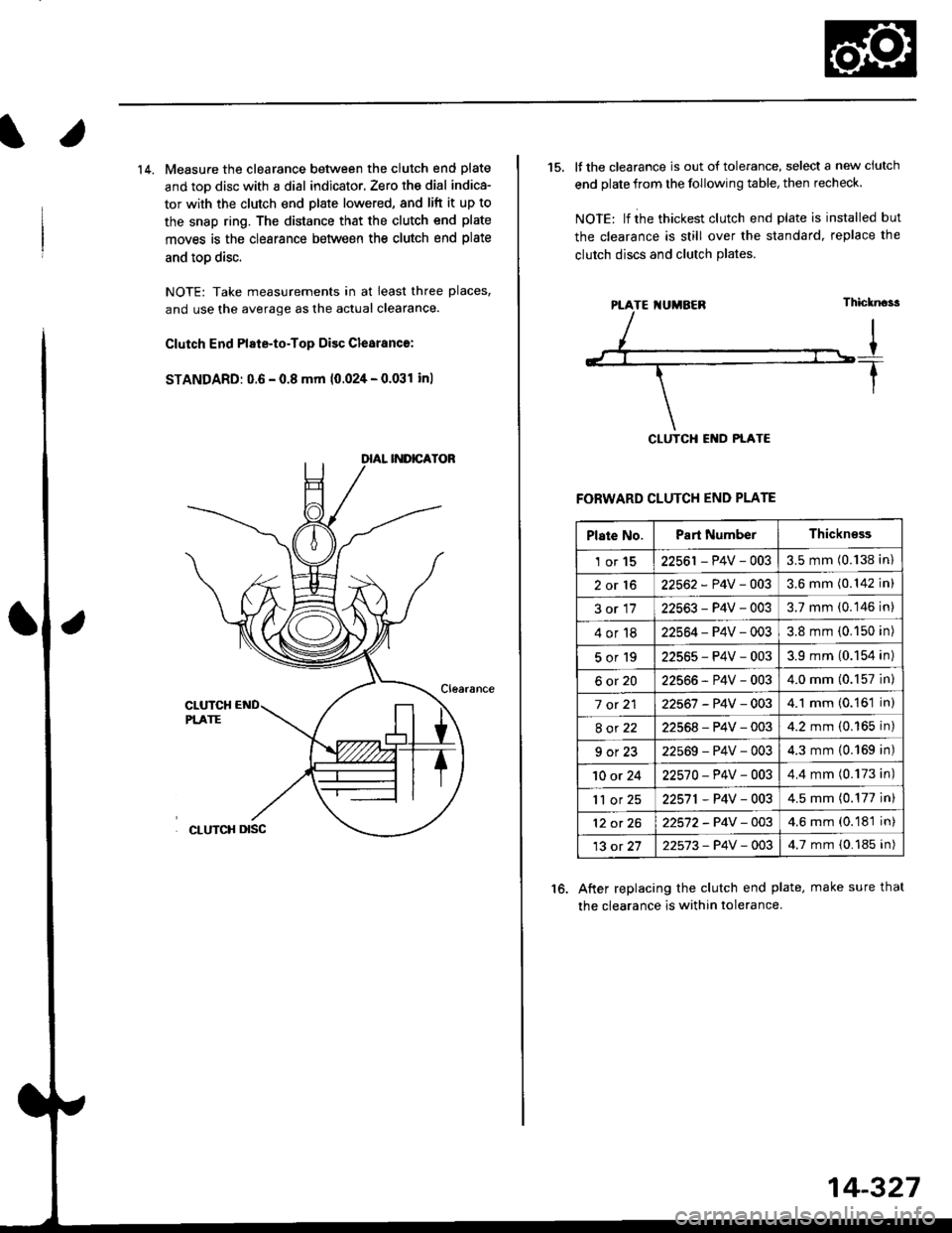
14. Measure the clearance between the clutch end plate
and toD disc with a dial indicator, Zero th€ dial indica-
tor with the clutch end plate lowered, and lift it up to
the snap ring. The distance that the clutch end plate
moves is the clearance between the clutch end plate
and toD disc.
NOTE: Take measurements in at least three places,
and use the average as the actual clearance.
Clutch End Plate-to-Top Disc Clesranc€:
STANDARD: 0.6 - 0.8 mm 10.024 - 0.031 inl
15. It the clearance is out of tolerance, select a new ciutch
end plate from the following table, then recheck.
NOIE: lf ihe thickest clutch end plate is installed but
the clearance is still over the standard, replace the
clutch discs and clutch Plates.
FORWARD CLUTCH END PLATE
After replacing the clutch end plate, make sure thal
the clearance is within tolerance.
16.
PTATE I{UMBEN
Plate No.Part NumberThickn€ss
1or1522561 - P4V - 0033.5 mm (0.138 in)
2or1622562 - P4V -OO33.6 mm (0.142 in)
3or1722563-P4V-0033.7 mm (0.146 in)
4or1822564 - P4V - 0033.8 mm (0.150 in)
5or192256s-P4V-0033.9 mm (0.154 in)
6ot2022566-P4V-0034.0 mm (0.157 in)
7 ot 2122567 -P4V -0034.1 mm (0.161 in)
8ot2222568-P4V-0034.2 mm (0.165 in)
9ot2322569-P4V-0034.3 mm {0.169 in)
10 or 2422570-P4V -OO34.4 mm (0.173 in)
'll or 2522571,P4V-0034.5 mm (0.177 in)
12 ot 2622572-P4V-OO34.6 mm (0.181 in)
13 ot 2722573-P4V -OO34.7 mm {0.185 in)
14-327
Page 1015 of 2189
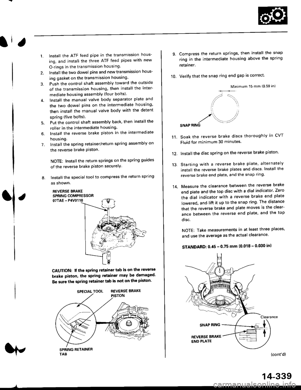
1.
7.
lnstall the ATF feed pipe in the transmission hous-
ing, and install the three ATF feed pipes with new
O-rings in the transmission housing,
Install the two dowel pins and new transmission hous-
ing gasket on the transmission housing.
Push the control shaft assembly toward the outside
of the transmission housing, then install the inter-
mediate housing assembly (four bolts).
lnstall the manual valve body separator plate and
the two dowel pins on the intermediate housing,
then install the rnanual valve body with the detent
spring (five bolts).
Put the control shaft assembly back, then install the
roller in the intermediate housing.
lnstall the reverse brake piston in the intermediate
housing.
Install the spring retainer/return spring assembly on
the reverse brake Piston.
NOTE: Installthe return springs on the spring guides
of the reverse brake piston securely
tnstall the special tool to compress the return spring
as shown.
REVERSE BRAKESPRING COMPRESSOR07TAE - P4V0110
6.
L
1
CAUTION: lf the spring retainer tab is on the reverse
brakc piston, the spring rstainer may be damaged'
Be sure the spring retainer tab is not on the piston'
rp
SPECIALTOOL REVERSEBRAKE
-^
14-339
10.
9.
14.
Compress the return springs, then install the snap
ring in the intermediate housing above the spring
retainer.
Verify that the snap ring end gap is correct'
Mini
/,,- '-t,,,,.
// \i/ ',r
'1 ,
.r' //'/. .-J?RINGSNAP
mum 15 mm 10.59 in)
Soak the reverse brake discs thoroughly in CVT
Fluid for minimum 30 minutes.
Installthe disc spring on the reverse brake piston'
Starting with a reverse brake plate, alternately
install the reverse brake plates and discs lnstall the
reverse brake end plate, and the snap ring'
Measure the clearance between the reverse brake
end plate and the top disc with a dial indicator' Zero
the dial indicator with a reverse brake end plate
lowered, and lift it up to the snap ring The distance
that the reverse brake and plate moves is the clear-
ance between the reverse end plate, and the top
disc.
NOTE: Take measurements in at least three places'
and use the average as the actual clearance'
STANDARD: 0.45 - 0.75 mm (0.018 - 0'030 in)
{cont'd)
11.
12.
13.
Page 1017 of 2189
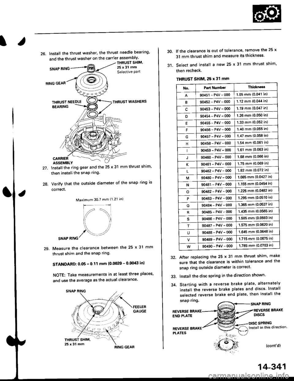
26. Install the thrust washer, the thrust needle bearing'
and the thrust washer on the carrier assembly'
SNAP RING
THRUST SHIM,
25x31 mm
Selective Pan
21.
24.
RING GEAR
THRUST NEEDLETHRUST WASHERS
EEARING
CARRIERASSEMBLY
lnstallthe ring gear and the 25 x 31 mm thrust shim,
then installthe snaP rrng.
Verify that the outside diameter of the snap ring is
correct,
Maximum 30.7 mm (1.21 in)
SNAP RING
Measure the clearance between the 25 x 31 mm
thrust shim and the snaP rlng.
STANDARD: O.O5 - 0.11 mm (0.0020 - 0.00'8 in)
NOTE: Take measurements in at least three places'
and use the average as the actual clearance
29.
,**r#*,".
'- t )
RING GEAR
14-341
30.
31.
lf the clearance is out of tolerance, remove the 25 x
31 mm thrust shim and measure its thickness'
Select and install a new 25 x 31 mm thrust shim.
then recheck.
THRUST SHIM, 25 x 31 mm
snap nng.RING
After replacing the 25 x 31 mm thrust shim, make
sure that the clearance is within tolerance and the
snap ring outside diameter is correct'
Install the disc spring in the direction shown'
Starting with a reverse brake plate, alternately
install the reverse brake plates and discs lnstall
selected reverse brake end plate, then install the
32.
33.
34.
REVERSEEND PLATE
BRAKE
Dtscs
SPRINGlnstall in this direction.
(cont'd)
REVERSEPI-ATES
No.Part Numb.lThickne*3
90451 - P4V - 0001.05 mm (0.041 in)
B90452-P4V-0001.12 mm (0.044 in)
c90453-P4V-000'1.19 mm (0.047 in)
D90454 - P4V - 000'l.26 mm (0.050 in)
90455-P4V-0001.33 mm (0.052 in)
F90456-P4V-0001.40 mm (0.055 in)
904s7-P4V-0001.47 mm (0.058 in)
90458-P4V-0001.54 mm (0.06'l in)
90459-P4V-000'1.61 mm (0.063 in)
J90460-P4V-0001.68 mm (0.066 inl
K90461-P4V-0001.75 mm (0.069 in)
90462-P4V-0001.82 mm (0.072 in)
M904a0-P4V-0001.085 mm (0.0427 in)
N90481-P4V-0001.155 mm (0.0454 in)
o901a2-P4V-0001.225 mm (0.0482 in)
90483-P4V-0001.295 mm (0.0510 in)
o90484-P4V-0001.365 mm (0.0537 in)
R904a5-P4V-0001.435 mm (0.0565 in)
90486-P4V-0001.5O5 mm (0,0593 in)
T90487-P4V-0001.575 mm (0.0620 in)
90488-P4V-00{)1.645 mm {0.0648 in)
90489-P4V-0001.715 mm (0.0675 in)
90490-P4V-0001.785 mm (0.0703 in)