1996 HONDA CIVIC Brake pedal switch
[x] Cancel search: Brake pedal switchPage 909 of 2189
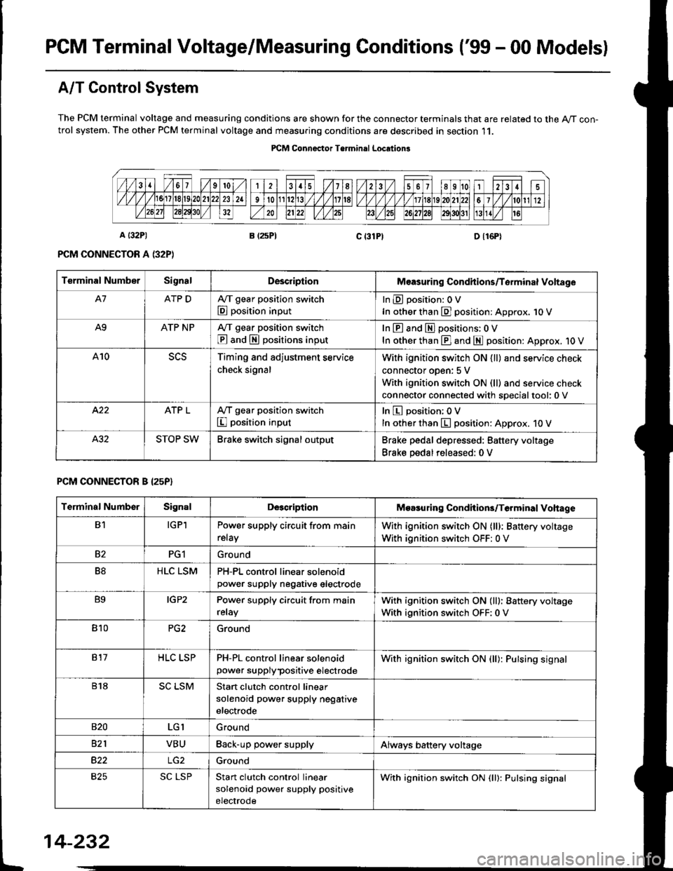
PGM Terminal Voltage/Measuring Conditions ('99 - 00 Modelsl
A/T Control System
The PCM terminal voltage and measuring conditions are shown for the connector terminals that are related to the A/T con-trol system. The other PCM terminal voltage and measuring conditions are described in section 11.
PICM Connoctor Terminrl Location3
Terminal NumberSignalDescriplionMeasuring Condhions/Torminal Voltage
A7ATP DA,/T gear position switch
E position input
InEposition:OV
In other than E] position: Approx. 1O V
A9ATP NPA/T gear position switch
@ and S positions input
In E and El positions: 0 V
In other than E] and E position: Approx. 1O V
A10Timing and adjustment service
check signal
With ignition switch ON {ll} and service check
connector oDen: 5 V
With ignition switch ON (ll) and service check
connector connected with soecialtool:0 v
ATP LA,/T gear position switch
I position input
In E position; OV
In other than E position: Approx. 10 V
STOP SWBrake switch signal outputBrake pedal depressed: Battery voltage
Brake pedal released: 0 V
PCM CONNECTOR B I25P}
Terminal NumberSignalDescriptionMoasuring Condhions/Terminal Vohage
B1IGPlPower supply circuit from main
relay
With ignition switch ON (lll: Battery voltage
With ignition switch OFF: 0 V
82PG1Ground
B8HLC LSMPH-PL control linear solenoidpower supply neqative electrode
B9IGP2Power supply circuit from main
relay
With ignition switch ON (lll: Battery voltage
With ignition switch OFF:0 V
810PG2Ground
817HLC LSPPH-PL control linear solenoid
power supplypositive electrode
With ignition switch ON {ll): Pulsing signal
818SC LSMStart clutch control linear
solenoid power supply negative
electrode
s20LGIGround
821VBUBack-up power supplyAlways battery voltage
B22Ground
825SC LSPStan clutch control linear
solenoid power supply positive
electrode
With ignition switch ON (ll): Pulsing signal
t
14-232
Page 970 of 2189
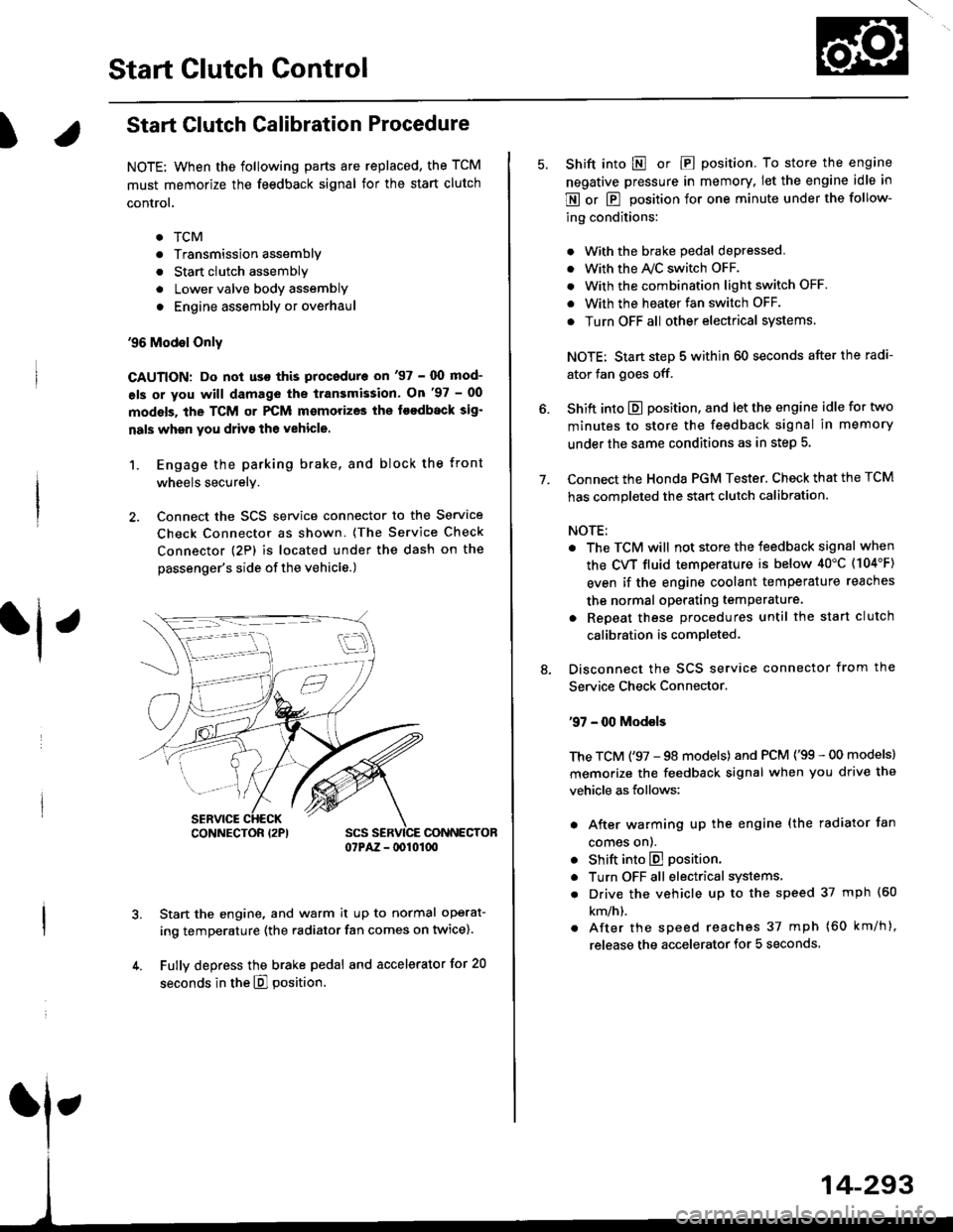
Start Clutch Control@
T
Start Clutch Calibration Procedure
NOTE: When the following parts are replaced, the TCM
must memorize the feedback signal for the start clutch
control.
. TCM
. Transmissionassembly
. Stan clutch assembly
. Lower valve bodv assembly
. Engine assembly or overhaul
'96 Model Only
CAUTION: Do not uso this procsdure on'97 - (X) mod-
els or you will damage the transmission. On '97 - 00
models, the TCM or PCM memorizes ths loodback sig'
nals when you drive the vehicle.
1. Engage the parking brake, and block the front
wheels securely.
2. Connect the SCS service connector to the Service
Check Connector as shown. (The Service Check
connector (2P) is located under the dash on the
passenger's side of the vehicle.)
CONNECTOR07PAZ - lDl01(xt
Start the engine, and warm it up to normal operat-
ing temperature (the radiator fan comes on twice).
Fully depress the brake pedal and accelerator for 20
seconds in the E] position.
rl ,
CONNECTOR I2PI
14-293
7.
Shift into E o|. E position. To store the engine
negative pressure in memory. Iet the engine idle in
E or E position for one minute under the follow-
ing conditions:
. With the brake pedal depressed,
. with the y'\/c switch oFF.
. With the combination light switch OFF.
. With the heater fan switch OFF.
. Turn OFF all other electrical systems
NOTE: Start step 5 within 60 seconds after the radi-
ator fan goes off.
Shift into E position, and let the engine idle for two
minutes to store the feedback signal in memory
under the same conditions as in step 5.
Connect the Honda PGM Tester. Check that the TCM
has completed the start clutch calibration.
NOTE:
. The TCM will not store the feedback signal when
the CVT fluid temperature is below 40"C (104'F)
even if the engine coolant temperature reaches
the normal operating temperature.
. Repeat these procedures until the start clutch
calibration is completed-
Disconnect the SCS service connector from the
Service Check Connector.
'97 - 00 Models
The TCM ('97 - 98 models) and PCM ('99 - 00 models)
memorize the feedback signal when you drive the
vehicle as follows:
. After warming up the engine (the radiator fan
comes onl.
. Shift into E position.
. Turn OFF all electrical systems,
. Drive the vehicle up to the speed 37 mph (60
km/h).
. After the speed reaches 37 mph (60 km/h),
release the accelerator for 5 seconds.
Page 975 of 2189
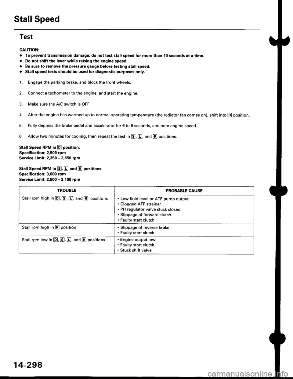
Stall Speed
Test
CAUTION:
. To prevent transmission damage, do not test stall sp€€d for mole than 10 seconds at a time.
. Do not shift the lsver whils raising the engine speod.
. Be sure lo remove the pressure gauge before tosting stall speed.
. Stall speed tssts should be used tor diagnostic purposes only,
1. Engage the parking brake, and block the tront wheels.
2. Connect a tachometer to the engine, and stan the engine.
3. Make sure the A/C switch is OFF.
4. After the engine has warmed up to normal operating temperature (the radiator fan comes on), shift into E position.
5. Fully depress the brake pedal and accelerator for 6 to 8 seconds, and note engine speed,
6. Allow two minutes for cooling, then repeat the test in E, E, and E positions.
Stall Speed BPM in E poshion:
Specification: 2,500 rpm
Servic€ Limit: 2,350 - 2.650 rpm
Stall Speed RPM in E, E and E positions:
Specitication: 3,000 rpm
Service Limit: 2,800 - 3,100 rpm
TROUBLEPROBABLE CAUSE
Stall rpm high in @. p. [, and @ positionsLow fluid level or ATF pump output
Clogged ATF strain€r
PH regulator valve stuck closed
Slippage of forward clutch
Faulty start clutch
Stall rpm high in E position. Slippage of reverse brake. Faulty start clutch
Stall rpm low in E, P, [, and @ positionsEngine output low
Faulty stan clutch
Stuck shift valve
14-294
Page 1159 of 2189
)
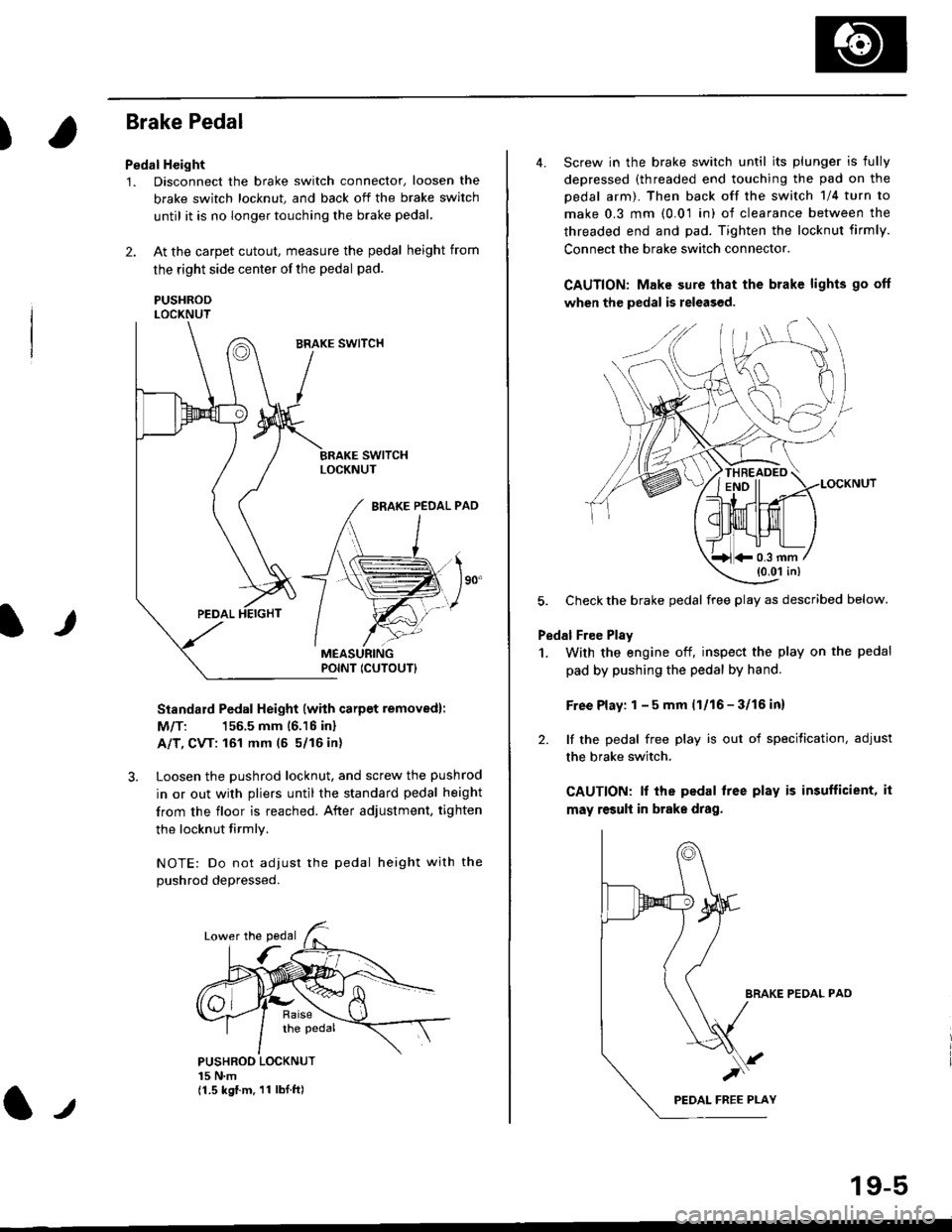
Brake Pedal
Pedal Height
1. Disconnect the brake switch connector, loosen the
brake switch locknut, and back off the brake switch
until it is no longer touching the brake pedal,
2. At the carpet cutout, measure the pedal height from
the right side center of the pedal pad.
PUSHRODLOCKNUT
Standard Pedal Height (with carpet removed):
M/T: 156.5 mm 16.16 inl
A/T, CVT: 161 mm (5 5/16 in)
3. Loosen the pushrod locknut, and screw the pushrod
in or out with pliers until the standard pedal height
from the floor is reached. After adjustment, tighten
the locknut firmly.
NOTE: Do not adiust the pedal height with the
Dushrod depressed.
It
PUSHROO LOCKNUT15 N.m(1.5 kgf.m. 11 lbI.ft)
POINT ICUTOUTI
4. Screw in the brake switch until its plunger is fully
depressed (threaded end touching the pad on the
pedal arm). Then back off the switch 1/4 turn to
make 0.3 mm (0.01 in) of clearance between the
threaded end and pad. Tighten the locknut firmly.
Connect the brake switch connector.
CAUTION: Make sure that the brake lights go off
when the pedal is released.
LOCKNUT
5. Check the brake pedal free play as described below.
Pedal Free Plsy
1. With the engine off, inspect the play on the pedal
pad by pushing the pedal by hand.
Free Play: 1 - 5 mm (1/16 - 3/16 inl
2. lf the pedal free play is out of specitication, adjust
the brake switch.
CAUTION: lf the pedal free play is insufficient, it
may result in brake drag.
BRAKE PEDAL PAO
)
19-5
*0.3 mm(0.01 in)
Page 1175 of 2189
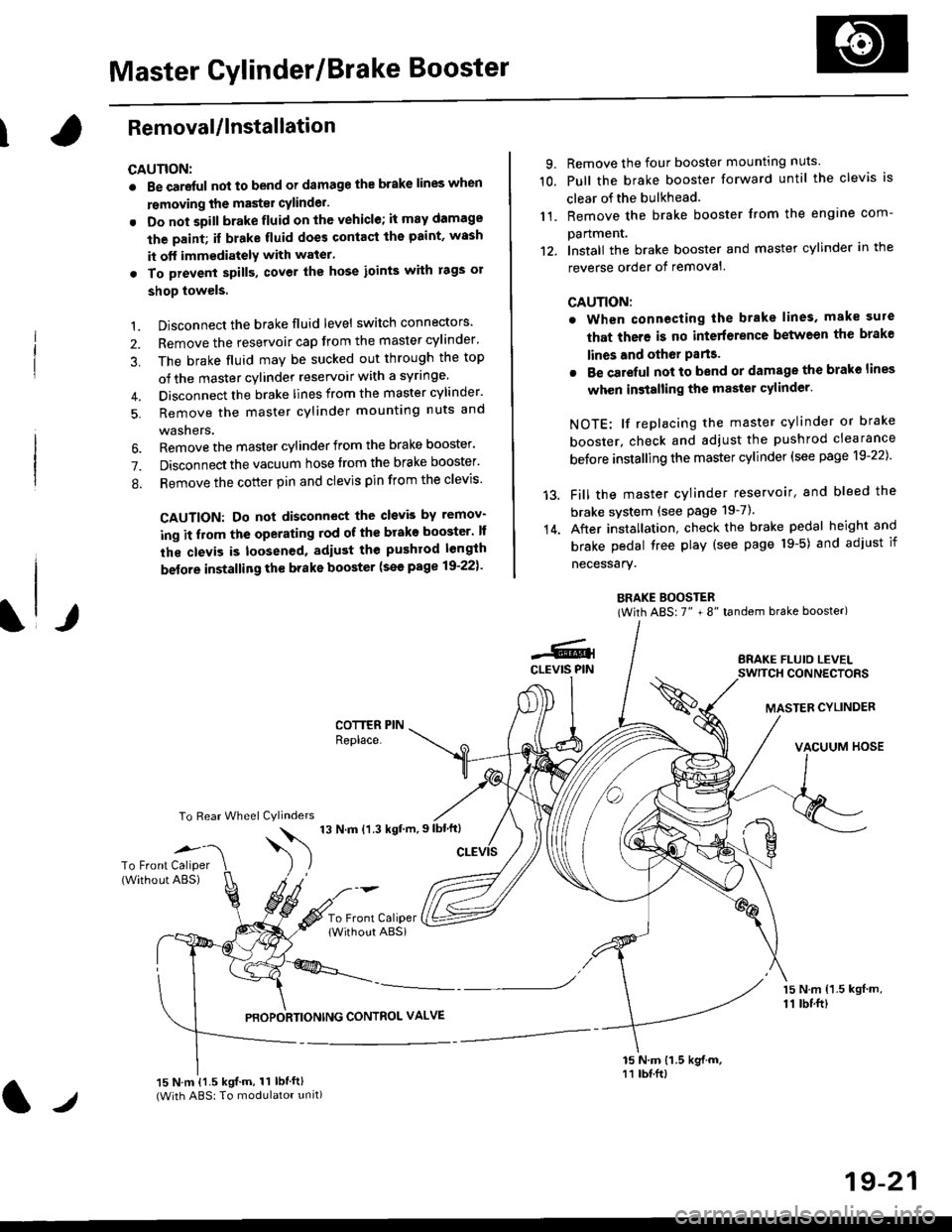
Master Cylinder/Brake Booster
IRemovaUlnstallation
CAUTION:
. Be care{ul nol to bend or damage the brake lines when
rsmoving the mastsr cYlinder.
. Do not soill brakefluid on the vehicle; it may damage
the paint; if brake fluid does contact the paint, wssh
it off immediatelY with water'
. To prevent spill3, cover the hose ioints with rags or
shop towels.
9. Remove the four booster mountlng nuts
10. Pull the brake booster forward until the clevis is
clear of the bulkhead.
11. Remove the brake booster from the engine com-
panmenr.'12. Install the brake booster and master cylinder in the
reverse order of removal.
CAUTION:
. When connecting the brake lines. make sure
that there is no inte erence between the brake
lines and oth6r Parts.
r Be careful not to bend or damage the brake lines
when installing the master cylinder.
NOTE: lf replacing the master cylinder or brake
booster, check and adiust the pushrod clearance
be{ore installing the master cylinder (see page 19-221'
Fill the master cylinder reservoir, and bleed the
brake svstem (see Page 19-7).
After installation. check the brake pedal height and
brake pedal tree play (see page l9-5) and adjust if
necessary.
BRAKE BOOSTER(With ABS: 7" + 8" tandem brake booster)
BRAKE FLUIO LEVELSWITCH CONNECTORS
MASTER CYLINDER
VACUUM HOSE
1.
2.
3,
5.
Disconnect the brake fluid level switch connectors'
Remove the reservoir cap from the master cylinder'
The brake fluid may be sucked out through the top
of the master cylinder reservoir with a syrlnge.
Disconnect the brake lines from the master cylinder'
Remove the master cylinder mounting nuts and
washers.
\l/
6. Remove the master cylinder from the brake booster'
7. Disconnect the vacuum hose trom the brake booster'
8. Remove the cotter pin and clevis pin from the clevis'
CAUTION: Do not disconnect the clevb by remov-
ing it from the operating rod of the brako booster' lf
the clevis is loosened, adiust the pushrod length
before installing th€ brake booster (see page 19-221'
COTTER PINReplace.
To Rear Wheel Cylinders
14.
-6.4CLEVIS PIN
To Front Caliper(Without ABS)$
t'N't'ttrnt'-''
To Front CaliperlWithout ABSi
PBOPORTIONING CONTROL VALVE
15 N.m {1.5 kgl m,11 tbtft)
15 N.m {1.5 kgif.m, 11 lbtft}(With ABS: To modulator unit)lr
19-21
Page 1205 of 2189
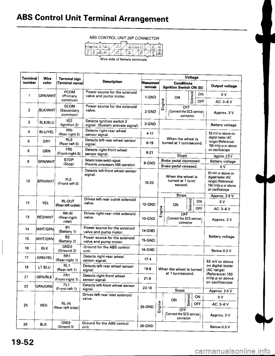
ABS Control Unit Terminal Arrangement
ABS CONTROL UNIT 26P CONNECTOR
Wire side of temale terminals
Terminalnumo0rWirecolorTerminal signTerminalnamoDgscriptionVoltage
Conditions(lgnition Switch ON flt))Output voltagoteminals
PCOM(Primary
common)
Power source for the solenoidvalve and pump motor.1-GNDON
=ONOV
AC: 3-6 V
BLK/WHTscoM(Secondary
common)
Power source for the solenoid
2.GNDOFF
lConnect the SCS service\
conneclor lApprox. 3 V
ELVBLUtG2(lgnition 2)Detects ignition switch 2
!9nal. (system activate signal)3-GNDBatt€ry voltage
BLU/YELRRO(Rear-right 0)Detects right-rear wheelsensor signal.4-17
When the wheel isturned at 1 turn/second.
53 mV or above ondigitaltester (ACra nge) {Fefera nce)150 mvp-p or aboveon oscilloscope
6GRYRLO(Rear-left 0)Detects left-rear wheel sensorsrgnal.6-19
8GRNFRO(Front-right 0)D€tects right-front wheelsgnsor srgnal,a-21StopsApprox.2.5VSTOP(Stop)hects brake switch signal.(Prevents unnecess€ry ABS operation)9-GNDBrake pedal depressed.Battery voltage
Brake pedal released.OV
10BRN^/vHTFLO(Front-left 0)
Detects left-front wheel sensorsignal.
10-23
When the wheel isturned at 1 turn/secono.
53 mV or above ondigitaltester (ACrange) (Referance)
150 mVFporaboveon oscilloscope
9!opsApprox. 2.5 V
12YELRLOUT(Rearjeft outlet)
Drives left-rear outlet solenoid
12.GNDON-9ONOV
OFFAC: 3^6 V
REDMHTRR]N(Rear-right
inlet)
Drives right-rear inlet solenoidvalve.13-GNDOFF
lconnect the SCS service]i connector IApprox. 3 V
14B1(Battery 1)Power source for the solenoidvatve and pump motor.14.GND
Battery voltage15WHT/G R N82(Baftery 2)Power source for the solenoidvarve ano pump motor.15.GND
r6BLKGND2{Ground 2)Ground for the ABS controlunit.16-GNDBelow 0.3 V
17GRN/'/ELRR1(Rear-right 1)Detects right-rear wheelsensor signal.17-4
When the wheel is turnedat 1 turn/second.
53 mV or aboveon digitaltester(AC range)(Referance) 150mVp-p or aboveon oscilloscope
19LT BLURLl(Rea.-left 1)Detects left-rear wheel sensorsagnal.19-6
GRN/BLKFRl(Front-right 1)Detects right-front wheelsensor signal.21-8
FL1(Front-left 1)Detects left-front wheel sensorsignal.23-10StopsApprox. 2.5 V
REDRL-IN(Rear-lett inletl
Drives left-r€ar inlet solenoid
25.GND
ut
ON
'6
-9ONOV
OFFAC: 3-6 V
OFF
lconnect the SCS service] connector lApprox. 3 V
BLKGND3(Ground 3)Ground for the ABS cgntrolunit.26.GNDBelow 0.3 V
19-52
Page 1209 of 2189
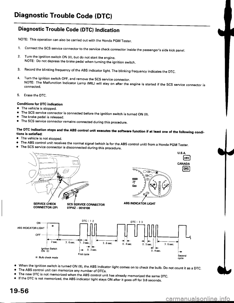
Diagnostic Trouble Code (DTCI
Diagnostic Trouble Code {DTC) Indication
NOTE: This operation can also be carried out with the Honda pGM Tesrer.
l connect the scs service connector to the service check connector inside the passenger,s side kick panel.
2. Turn the ignition switch ON (||). but do not start the engine.NOTE: Do not depress the brake pedal when turning the ignition switch.
3 Record the brinking frequency of the ABS indicator right. The brinking frequency indicates the DTc.
4, Turn the ignition switch OFF, and remove the SCS service connector.NorE: The Mslfunction Indicator Lamp (MlL) will stay on after the engine is started if the scs service connector isconnected.
5. Erase the DTC.
Condhions for DTC indication. The vehicle is stoDDed.. The SCS service connector is connected before the ignition switch is turned ON fll).. The brake pedal is released.. Th€ SCS service connector remains connected during this procedure
The DTG indication stops 8nd the ABs conltol unit executes the softwaro tunqtion if at least one of the following condi-tions b satisfied:
o The vehicle is not stoDoed.' The ABS control unit receives the normat signal (which is for the ABS controt unit) from a Honda pGM Tester.. The SCS service connector is disconnected during this procedu.e,
u.s.A.
@
CANADA
@
SERVICE CHECKCONNECTOR {2PISCS SERVICE CONNECTOR07PAZ - 0010100
ABS INDICATOR LIGHT
DTC : 3 3
A8S INDICAIOR LIGHT
Snilion swirch
' when the ignition switch is turned oN (ll), the ABs indicator light comes on to check the bulb. Do not count it as a DTc.o The ABS control unit can memorize any number of DTCs.. The new DTC is not memorized when the ABS control unit has already memorized the same DTC,.lftheDTCisnotmemorized,theABSindicatorlightstaysONafteritgoesofffor3.6seconds.
19-56
Page 1210 of 2189
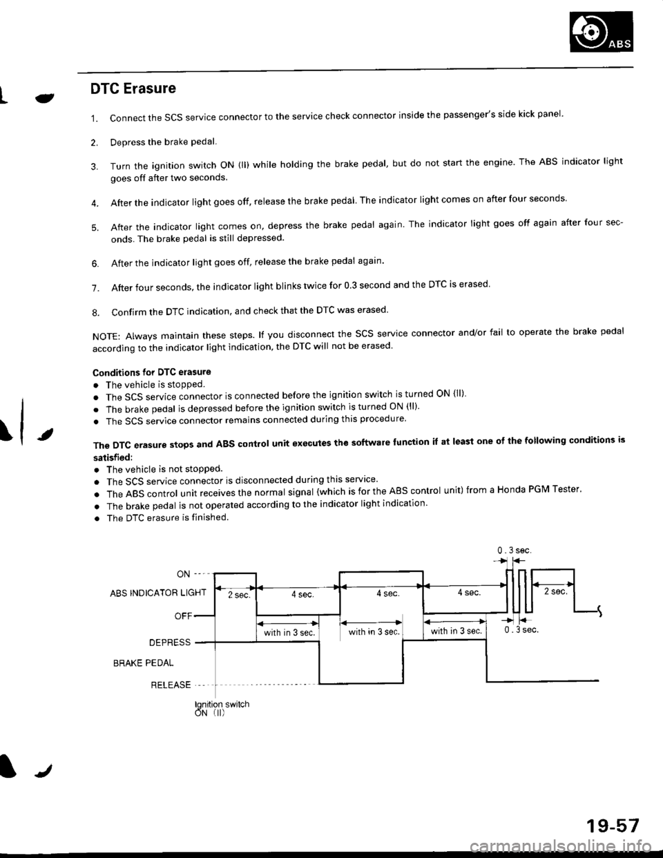
LJDTG Erasure
1.
2.
Connect the SCS service connector to the service check connector inside the passenger's side kick panel.
Depress the brake pedal.
Turn the ignition switch oN (ll) while holding the brake pedal, but do not start the engine. The ABS indicator light
goes off after two seconds.
After the indicator light goes off, release the brake pedal The indicator lightcomeson after four seconds
After the indicator light comes on, depress the brake pedal again. The indicator light goes off again after four sec-
onds. The brake pedal is still depressed.
4.
5.
\t
6. After the jndicator light goes off, release the brake pedal again'
7. After four seconds, the indicator light blinks twice for 0 3 second and the DTC is erased
8. Confirm the DTC indication, and check that the DTC was erased
NOTE: Always maintain these steps. lf you disconnect the scs service connector and/or fail to operate the brake pedal
according to the indicator light indication, the DTC will not be erased
Conditions for DTC erasure
o The vehicle is stopped.
. The SCS service connector is connected before the ignition switch is turned ON {ll)
. The brake pedal is depressed before the ignition switch is turned ON (ll)'
. The SCS service connector remains connected during this procedure
The DTC erasure stops and ABS control unit executes the software lunction it at least one ot the following conditions is
satisfied:
o The vehicle is not stopped.
. The SCS service connector is disconnected during this servace'
.TheABscontro|unitreceivesthenormaIsigna|(whichisfortheAEscontro|unit)fromaHondaPGMTester'
. The brake pedal is not operated according to the indicator light indication
. The DTC erasure is finished
ABS INDICATOR LIGHT
OFF
DEPRESS
BRAKE PEDAL
RELEASE
0.3sec
lqnition switchoN (I)
J
19-57