1996 HONDA CIVIC B16
[x] Cancel search: B16Page 287 of 2189

System Description
Vacuum Gonnections (cont'd)
B16A2 engine:
EVAPORATIVE EMISSION (EVAPICONTROL CANISTERVENT SHUT VALVE
To EVAPORATIVE EMISSION(EVAPI CONTROL CANISTERFILTER
EVAPORATIVEEMISSION {EVAPIPURGE CONTROLCANISTER
To EVAPOBATTVE EM|SS|ON(EVAPI
TWO WAY VALVE
EVAPORATIVEEMISSION IEVAPIPUBGE CONTROL SOLENOIDVALVE
2
VEHICLE
MANIFOI.D ABSOLUIEPRESSURE (MAPI SENSOR
FUEL PRESSUREREGULATOR
To CRUISECONTROLDIAPHRAGM(with cruise control)
1 1-18
Page 362 of 2189
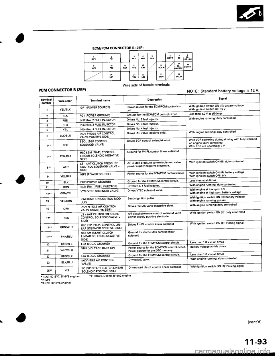
ECM/PCM CONNECTOR B (25PI
Wire side of female terminals
FCM CONNECTOR B {25P)NOTE: Standard battery voltage is 12 V
Sign.l
YELtsLKIGP1 IPOWER SOUflCE)Powor sou rca for the ECM/PCM conlrolcirwhh ignilion swilch ON (ll)ibatteryvoltageWith ignition switch OFF:0 V
BLKPGl {POWEB GNOUND)Ground fo. the ECM,/PCM contrclcncuit'Less than 1.0 V at slltimes
FEDlNJ2 (No 2 FUEL INJECIOR)Drives No. 2 fu€l inieclor'Wirh enqine runnin9: dulv conlroll6d
BLUlNJ3 (No.3 FUEL INJECTOB)Orives No.3 fuel inieclor'
YELlNJ,r lNo. 4 FUEL INJECTOF)Drives No. 4 luel injector'
6BLI(BIUIACV P (IDLE AIR CONTROLVAIVE POSITIVE SIDE)O.iv€s IAC valve {Posirivo side)Wilh engine running: duty conrrollod
BEDESOL {EG8 CONTROLSOLENOID VALVE)Drives EGF controlsolonoid valveWith EGR operaiing during driving wirh follv warmedup onginsl dutY controlledWilh EGR nol op€r.ring:0 V
PNKSLKHlC tstvr (PH-PL CONTnOLLINEAfl SOLENOID NEGATIVEst0E)
G rcund for PH-PL control linsar solsnoid
8.,LS - (A/T CLUTCH PFESSURECONTROL SOTENOIDVALVE'sroE)
A/Tclutch prsssure conrrol sol€nod valv€pow6r slpply negative elecrodeWith ignilion swirch ON (ll):dutv controll€d
9YEUBLKrGP2 {POWE8 SOUFCE)Powor $urce for lhe ECI{,'PCM controlc'rcuitwnh ignirion swirch ON (ll): ban€ry voltag€with ignirion swnch oFF:0 v
10BLKPG2IPOWER GSOUNDIGround lor ths ECM/PCM controlctrcuil
118RNINJl {No,1 FUEL INJEqIOR)orives No. r ru6l Iniocror.With onsino at low lpm:0Vwith ens,n. ar hish tpm:bsneryl9!9gl-12"GRN,.YELWS (WEC SOLENOID VALVE)Orivos WEC solanoid v.lvs.
13YEUGRNICM {I6NITION CONTROL MODULE}
With ignition switch ON (ll)r b5n6ry volt€gsWilh engino running: Puls6
15ORNIACV N (IDLE AIN CONTSOIVALVE NEGATIVE SIOE)Drivos the IAC valve lnogativ€ 3idelWith €ngin€ ru nningi dr]tv controlled
REDLS + (A,/T CIUICH PRESSURECONTFOT SOIENOIOVALVE +SIDE}
A/T clutch pr€so.6 controlsolenoid valvepow6r slpply posiliv€ oroclrodeWirh ignition swatch ON (lll: dutYcontrorled
HLC LSP (PH-PI CONTROI LIN.EA8 SOLENOID POSITIVE SIDE)Orives PH-PL control line€r solenoidWith qnition switch ON (lll: Pulsing srgnal
PNK/BTUSC LSM (STAfiT CLUTCHLINEAR SOLENOIO N€GATIVESIDE)
Groundforstartclutchcontrol line6r
20BnN/AtKLGI (LOGIC GEOUNO)Ground for lh€ EcM/PcM controlcircuit'L6se rhan 1.0 v.i alltimes
21VBU IVOLTAGE 8AC( UP)Powet source torlhe ECM/PCM control circuitPower sourco tor th6 DTC m€mory'Battaryvoltage aitnEtrmes
22BFN/8IKLG2 (LOGIC GSOUND)Ground iorths ECMnCM conrrol circuir'tsss thah 1.0 v al all times
238LI(BLUIACV (IOTE AIR CONTROLWitn ongine funning: dutv conrol!6d
25'3YELSC LSP {STANT CLUTCH LINEARsotENorD PoSlrlvE slDE)Orives sran clutch control linesr solonoid.With ignilion swilch ON (ll): Pulsing sign3r
r1: A/r (D16 , D16Y8 ensins)
'3:CVT {O16Y5ensino)
'4: Ol6Y5, Dl6Y8, B164? onsina
(cont'd)
1 1-93
Page 367 of 2189
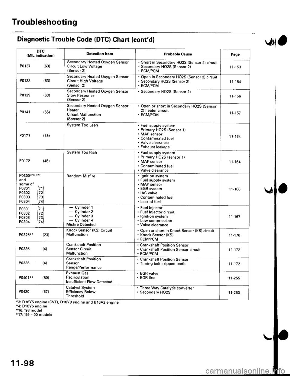
Troubleshooting
DTClMlL indicationlDatection hsmProbablo CausePage
P0137(63)Secondary Heated Oxygen SensorCircuit Low Voltage(Sensor 2)
Short in Secondary HO2S lSensor 2) circuitSecondary H02S {Sensor 2)ECM/PCI\41 1-153
P0r38 {63)Secondary Heated Oxygen SensorCircuit High Voltage(Sensor 2)
Open in Secondary HO2S (Sensor 2) circuitSecondary HO2S (Sensor 2)EC[I/PCM11-154
P0'139 (63)Secondary Heated Orygen SensorSlow Response(Sensor 2)
Secondary H02S lSensor 2)1l-156
P0141 (65)
Secondary Heated Oxygen SensorHeaterCircuit Malfunction(Sensor 2)
. Open or short in Secondary HO2S (Sensor2) heater circuit. ECM/PCM11-157
P0171 (45)
System Too LeanFuel supply systemPrimary HO2S (Sensor 1)MAP sensorContaminated fuelValve clearanceExhaust leakage
11,164
P0172 (45)
System Too RichFuel supply systemPrimary HO2S (sensor l)MAP sensorContaminated fuelValve clearance
11-164
P0300*16' }l?
andsome ofPo3o1 /r'' \P0302 l72lP0303 l73lP0304 \7 4l
Random Misfirelgnition systemFuel supply systemMAP sensorEGR systemIAC valveContaminated fuelLack of fuel
r1-r66
P0301P0302P0303P0304
/rt\172ll73l\7 4l
- Cylinder 1- Cylinder 2- Cylinder 3- Cylinder 4Misfire Detected
Fuel InjectorFuel Injector circuitlgnition systemLow compressionValve clearance
11 167
P0325*3 (23)Knock Sensor (KS) CircuitMalfunctionOpen or short in Knock Sensor (KS) circuitKnock Sensor {KS)ECM/FCtvl11-170
P0335(4)Crankshaft PositionSensor CircuitMalfunction
Crankshaft Position SensorCrankshaft Position Sensor circuitECM/PCM11-172
P0336(4)Crankshaft PositionSensorRange/Performance
. Crankshaft Position Sensor. Timing belt skipped teeth11-172
P040'�r*r (80)Exhaust GasRecirculationInsufficient Flow Detected
' EGR valve. EGR line
P0420(67)Catalyst SystemEfficiency BelowThreshold
. Th.ee Way Catalytic converter. Secondary HO2S11 253
Diagnostic Trouble Code (DTCI Chat (cont'dl
*3: D16Y5 engine (CVT), D16Y8 engine and B1642 engine*4: D'16Y5 engine*16: '98 model+17: '99 - 00 models
,Jla
1 1-98
Page 500 of 2189

tJFuel Pressure {'97 and later Models)
ReliGving
Before disconnecting tuel pipes or hoses, release pres-
sure from the system by loosening the 12 mm banjo
bolt on top of the fuel filter.
@o Do not smoke whilo working on the fuel sy3lom.
Ksgp op€n flames or sparks away tlom Your work
arga.
. Be sure to relieve fuel pressule while the ignition
swhch is off.
1. Write down the frequencies for the radio's preset
buttons,
2. Disconnect the battery negative cable from the bat-
tery negative terminal.
3. Remove the fuel fill cap.
Use a box end wrench on the 12 mm banjo bolt at
the fuel filter while holding the fuel filter with anoth-
er wrench.
Place a rag or shop towel over the 12 mm banio bolt.
Slowly loosen the 12 mm banjo bolt one complete
turn.
4.
I
12 mm BAtt OBOLT33 N.m (3.i1 kgf m,25 tbf.f0
NOTE: Replace all the washers whenever the 12
mm banio bolt is loosened or removed.
Inspaqtion
1. Relieve fuel pressure.
2. Remove the 12 mm banjo bolt from the fuel filter
while holding the fuel Jilter with another wrench
Attach the special tools.
3. Start the enginethe fuel Pressure with the
engine idling and the vacuum hose of the fuel pres-
sure regulator disconnected from the fuel pressure
regulator and pinched lfthe engine will not start, turn
the ignition switch ON {ll), wait for two seconds, turn
it off, then back on again and read the fuel pressure'
Pr$3uro ehould be:
excepi 816A2 sngine:
260 - 310 kPa {2'7 - 3.2 kgf/cm" 38 - {6 Fi}
B16A2 engine:
27O -32O kPa P.8 - 3'3 kgf/cm'�, '10 - 47 psi)
4. Reconnect vacuum hoso to the fuel pressure regulator'
Pre33ure 3hould be:
except B16A2 engin€:
2OO - 250 kPa {2.0 - 2'5 kgf/cm'�, 28 - 36 psi)
B16A2 engino:
210 - 260 kPa 121 - 2.6 ksf/cm'�, 30 - 37 psi)
lf the fuel pressure is not as specified, first check the
fuel pump (see page 11-236) lfthetuel pumpisoK,
check tho following:
. lf the fuel pressure is higher than specified,
inspect for:- Pinched or clogged fuel return hose or line.
- Faulty fuel pressure regulator (see page 11-
2341.
. lf the fuel pressure is lower than specified, inspect
for:- Clogged fuel filter.
- Faulty fuel pressure regulator (see page l1-
2341.- Fuel line leakage.
FUEL PRESSUREADAPTER BOLT, 12 mm
tguxt8-PD6-0101
CLAMP
REGULATOR
11-231
Page 518 of 2189
\
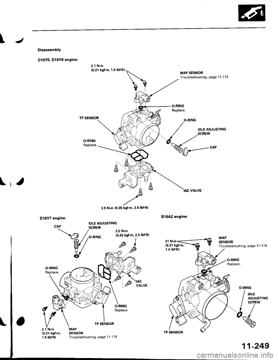
Disasssmbly
Dl6Y5, Dl6Y8 engine:
2.1 N.m(0.21 ksf.m, 1.5 lblftl\
bY
TP SENSOR
MAPSENSORTroubleshooting, Page 11 115
3.5 N.m t0.35 kgl m,2.5 lblftl
B16A2 sngine:
MAP SENSORTroubleshooting, page 1 1'1 15
IDLE AOJUSTING
MAPSENSORTroubleshooting, Page 1 1-1 19
z.'�t N.m10.21 kgf'm,1.5 tbf.frl
TP SENSOR
11-249
Page 663 of 2189
rla
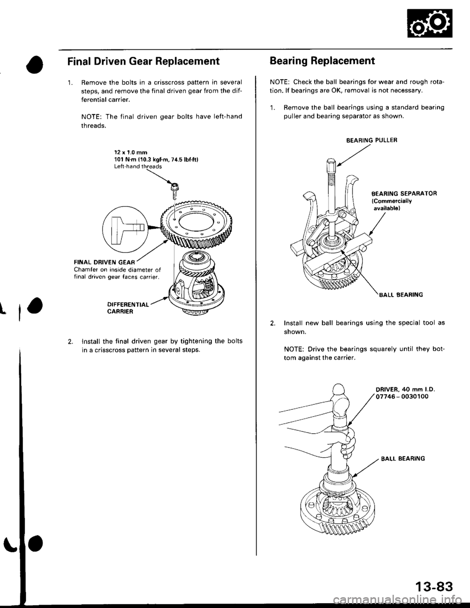
Final Driven Gear Replacement
'1. Remove the bolts in a crisscross pattern in several
steps, and remove the final driven gear from the dif-
ferential carrier.
NOTE: The final driven gear bolts have left-hand
threads,
12 x 1.0 mm101 N.m {'10.3 kgf.m,74.5 lbf.ftlLeft hand
FINAL DRIVEN GEARChamfer on inside daameter offinal driven gear faces carrier.
2. Install the final driven gear by tightening the bolts
in a crisscross pattern in several steps.NOTE: Drive the bearings squarely until they bot-
tom against the carrier.
BALL BEARING
13-83
Bearing Replacement
NOTE: Check the ball bearings for wear and rough rota-
tion. lf bearings are OK, removal is not necessary.
1. Remove the ball bearings using a standard bearing
puller and bearing separator as shown.
BEARING PULLER
BEARING SEPARATOR
lCommerciallyavailab16)
BALL BEARING
2. Install new ball bearings using the special tool as
shown.
Page 1088 of 2189
Inspection and Adjustment
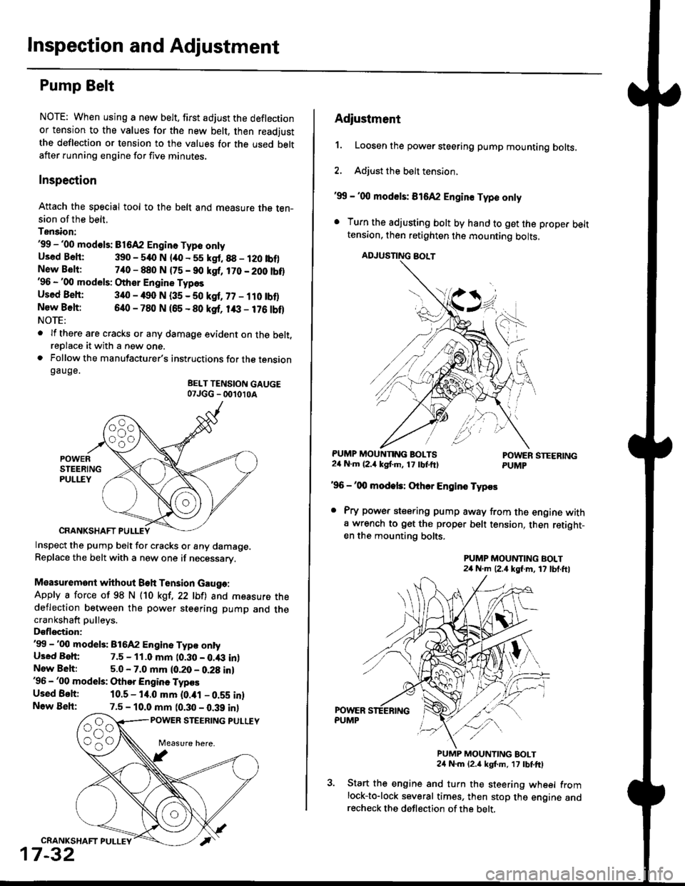
Pump Belt
NOTE: When using a new belt, first adjust the deflection
or tension to the values for the new belt, then readjust
the deflection or tension to the values for the used beltafter running engine for five minutes.
Inspection
Attach the special tool to the belt and measure the ten-sion of the belt.
Tension:'99 -'00 mod€ls: B1642 Engin. Type onlyUsed Bsh: 390 - 540 N lao - 55 kgt.88 - 120 tbf)New Belt:740 - 880 N {75 - 90 kgf, 170 - 200 tbt}'96 - '00 models: Other Engine Types
Used Beh: 340 - 490 N (35 - 50 kgf, 77 - ilO tbflNew Belt:640 - 780 N 165 - 80 ksf, 1& - 176 tbf)NOTE:
. lf there are cracks or any damage evident on the belt,reDlace it with a new one.. Follow the manufacturer's instructions for the tensiongauge.
BELT TENSION GAUGE07JGG _ 001010A
Inspect the pump belt for cracks or any damage.Replace the belt with a new one if necessary.
Measuremont without Beh Tension Gauga:
Apply a force of 98 N (10 kgt,22 lbfl and measure thedeflection between the power steering pump and thecrankshaft pulleys.
Dsflectior:'99 -'00 model3: 816A2 Engine Typ€ ontyUsed Beh: 7.5 - 11.0 mm t0.30 - 0.43 inlNew Beh:5.0 - 7.0 mm (0.20 - 0.28 in)'96 - '00 models: Othor Engine Typos
Used Behi 10.5 - 14.0 mm (0.ial - 0.59 inlNow Beh:7.5 - 10.0 mm (0.30 - 0.39 inl
POWER STEERING PULUY
CRANKSHAFT PULLEY
17-32
Adiustment
1. Loosen the power steering pump mounting bolts.
2. Adjust the belt tension.
'99 - '00 mod€ls: 816A2 Engin€ Typo only
. Turn the adjusting bolt by hand to get the proper belttension, then retighten the mounting bolts,
ADJUSNNG BOLT
PUMP MOUNNNG BOLTS24 N.m (2.4 kgf'm, 17 tbtftlPOWER STEERINGPUMP
'96 -'00 modek: Othcr Engins Typos
. Pry power steering pump away from the engine witha wrench to get the proper belt tension, then retight-en the mounting bolts.
PUMP MOUNTING BOLT24 N.m (2,4 kgf.m, 17 lbl.ftl
PUMP MOUNTING BOLT24 N.m {2.a kgt m, 17 tbtftl
Start the engine and turn the steering wheel fromlock-to-lock several times, then stop the engine andrecheck the deflection of the belt,
Page 1467 of 2189
A/G GomPressor Belt
Adjustment
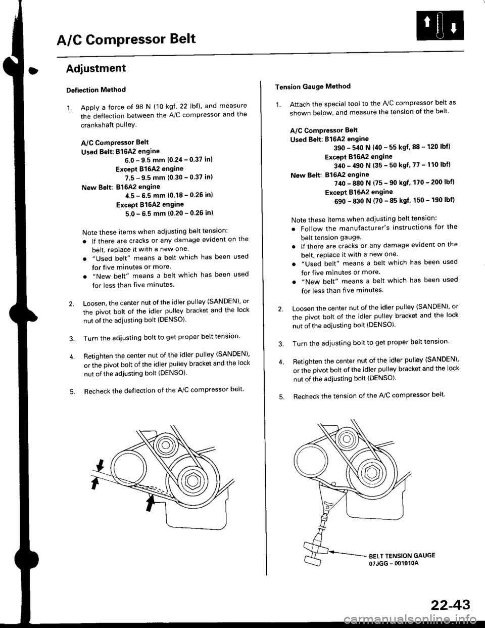
Detlection Method
'1. Apply a force of 98 N (10 kgf, 22 lbf), and measure
the deflection between the A,/C compressor and the
crankshaft PulleY
A/C ComPressor Belt
Used Belt: 816A2 engine
6.0 - 9.5 mm 10 2'l - 0.37 inl
Except 816A2 engine
7.5 - 9.5 mm (0.30 - 0.37 in)
New Belt: 816A2 engine
4.5- 6 5 mm (0.18-0.26 in)
Except 815A2 engine
5.0-5 5 mm (0.20-0.26 inl
Note these items when adjusting belt tens'on:
. lf there are cracks or any damage evident on the
belt, replace it with a new one.
. "Used belt" means a belt which has been used
for five minutes or more.
. "New belt" means a belt which has been used
tor less than five minutes.
2. Loosen, the center nut ofthe idler pulley (SANDEN), or
the pivot bolt of the idler pulley bracket and the lock
nut ofthe adjusting bolt (DENSO).
3. Turn the adjusting bolt to get proper belt tension'
4. Retighten the center nut of the idler pulley (SANDEN),
or the pivot bolt of the idler pulley bracket and the lock
nut of the adjusting bolt (DENSO).
5. Recheck the deflection of the A,/C compressor belt'
Tension Gauge Method
1. Attach the special tool to the IVC compressor belt as
shown below, and measure the tension of the belt
A/C Compressor Belt
Used Belt: 816A2 engine
390 - 540 N (40 - 55 kgf, 88 - 120 lbll
Except 816A2 engine
340 - 490 N (35 - 50 ksf, 77 - 110 lbfl
New Belt: B16A2 engine
?40 - 880 N {75 - 90 ksf' 170 - 200 lbf)
Except Bl642 engine
690 - 830 N (70 - 85 ksf, 150 - 190 lbf)
Note these items when adjusting belt tension:
. Follow the manufacturer's instructions for the
belt tension gauge.
. lf there are cracks or any damage evident on the
belt, rePlace it with a new one.
. "Used belt" means a belt which has been used
for five minutes or more.
. "New belt" means a belt which has been used
for less than five minutes
2 Loosen the center nut of the idler pulley (SANDEN)' or
the pivot bolt of the idler pulley bracket and the lock
nut of the adjusting bolt (DENSO).
3. Turn the adjusting bolt to get proper belt tension
4. Retighten the center nut of the idler pulley (SANDEN),
or the pivot bolt of the idler pulley bracket and the lock
nut of the adjusting bolt (DENSO)
5. Recheck the tension of the A/C compressor belt'
22-43