Page 583 of 2189
MaintenanceBack-up Light Switch
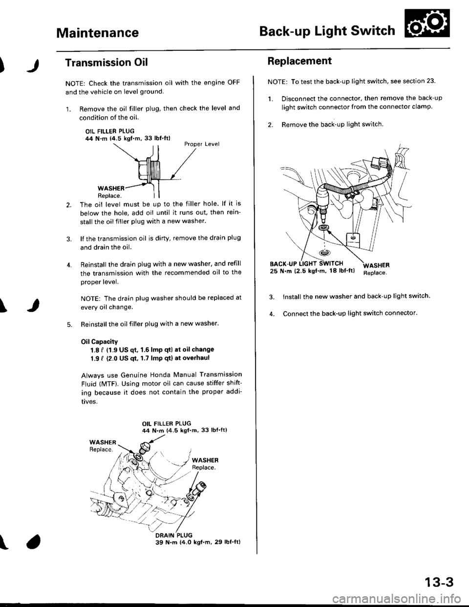
Transmission Oil
NOTE: Check the transmission oil with the engine OFF
and the vehicle on level ground.
1. Remove the oil filler plug, then check the level and
condition of the oil.
OIL FILLER PLUG/14 N.m (4.5 kgl.m,33 lbl.ft)Proper Level
4.
WASHERReplace.
The oil level must be up to the filler hole. lf it is
below the hole, add oil until it runs out. then rein-
stall the oil filler plug with a new washer.
lf the transmission oil is dirty, remove the drain plug
and drain the oil.
Reinstall the drain plug with a new washer, and refill
the transmission with the recommended oil to the
proper lever.
NOTE: The drain plug washer should be replaced at
every oil change.
Reinstall the oil filler plug with a new washer.
OilCapacity
1.8 f (1.9 US qt. 1.6 lmp qtl at oil change
1.9 { (2.0 US $, 1.7 lmp qt) at overhaul
Always use Genuine Honda Manual Transmission
Fluid {MTF). Using motor oil can cause stiffer shift-
ing because it does not contain the proper addi-
t|ves.
\
\
Replacement
NOTE: To test the back-up light switch, see section 23
1. Disconnect the connector, then remove the back-up
light swirch connector from the connector clamp.
2. Remove the back-up light switch.
25 N.m (2.5 kgf'm, 18lbf'ltl
Install the new washer and back-up light switch
Connect the back-up light switch connector.
ASHER
13-3
Page 585 of 2189

Transmission Assembly
I
Removal
@. Make sure iacks and safety stands are placed prop€dy,
and hoist brackets are atlach€d to correct position on
the enginc.
. Apply parking brake and block rear whosls so car will
nol roll olf stands and lall on you while working under
it.
CAUTION: Use fender covers to svoid damaging painted
surfaces.
1. Disconnect the negative {-) cable first, then the pos-
itive (+) cable from the battery'
Drain transmission oil {see page 13-3).
Remove the intake air tube. intake air duct and air
cleaner housing assembly (see section 5).
Disconnect the starter motor cables, transmission
ground wire and back-up light switch connector.
6x1.0 mm BACK-UP LIGHT
9.8 N.m (1.0 ksf.m, 7.2 lbI.ft) swlTcH CoNNECTOR
8x 1 .25 mm8.8 N.m {0.9 kgt.m,6.5 lbf.ftl
\
ARTER
5. Remove the wire harness clamps.
vssCONNECTOR
6. Disconnect the vehicle speed sensor (VSS) connec-
ror.
Remove the clutch line bracket, clutch line clamp,
and slave cvlinder.
CAUTION:
. Do not opsr.te tho clutdh pedal once the 3lavc
cylindor has b6on romoved.
. Tske care not to bend tha clutch lin6.
7.
(cont'd)
13-5
Page 627 of 2189
MaintenanceBack-up Light Switch
\
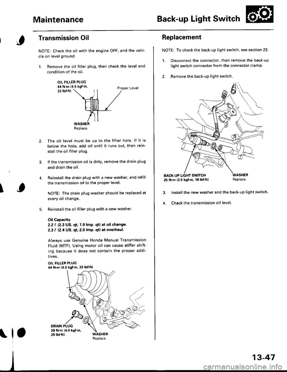
Transmission Oil
NOTE: Check the oil with the engine OFF. and the vehi-
cle on level ground.
1. Remove the oil filler plug, then check the level and
condition of the oil.
OIL FILLER PLUGia4 N.m {{.5 kgf'm,Proper Level33 tbtfrl
The oil level must be up to the filler hole. lf it is
below the hole, add oil until it runs out, then rein-
stall the oil filler plug.
lf the transmission oil is dirty, remove the drain plug
and drain the oil.
Reinstall the drain plug with a new washer. and refill
the transmission oil to the proper level.
NOTE: The drain plug washer should be replaced at
every oil change.
Reinstallthe oilfiller plug with a new washer.
Oil Capacity
2.2 f {2.3 US. qt, 1.9 lmp. qtl at oil change.
2.3 f {2./f US. qt. 2.0 lmp. qt} at overhaul.
Always use Genuine Honda Manual Transmission
Fluid (MTF). Using motor oil can cause stiffer shift-
ing because it does not contain the proper addi-
tives.
OIL FILLER PLUGila N.m {4.5 kgf.m, 33 lbt'ftl
Replace.
\1,
Replacement
NOTE: To check the back-up light switch, see section 23.
1. Disconnect the connector, then remove the back-up
light switch connector from the connector clamp.
2. Remove the back-up lighr switch.
AACK.UP25 N.m 12.5 kgf.m, 18 lbf'tt)Replace.
lnstall the new washer and the back-up light switch.
Check the transmission oil level.4.
Page 628 of 2189

Transmission Assembly
l
,
{
Removal
@Make sure iacks and safoty stands are placad plop-
erly (3ee section l).
Apply parking braks and block rear wheels so car
will not roll off stands and fall on you while working
under il.
CAUTION: Us6 fonder cove6 to avoid damaging painted
sudaces.
Disconnect the negative (-) cable from the battery,
then the positive (+l cable.
Drain the transmission oil. then reinstall the drain
plug with a new washer (see page 13-47).
Remove the intake air duct and the air cleaner hous-
ing assembly (see s€ction 5).
Disconnect the back-up light switch connector and
the transmission ground wire.
Remove the lower radiator hose clamp from the
transmission hanger B.
L
8 x 1 .25 mm22Nm12.2kgl'm�,
LOWER RADIATORHOSE CLAMP
16 rbtft)
13-48
7.
Bemove the wire harness clamps.
Disconnect the starter motor cables and the vehicle
speed sensor (VSS) connector.
8 x 1.25 mm8.8 N.m (0.9 kgf.m,6.5 tbtftl
STARTERMOTORCABLES
8. Remove the clutch line bracket and the slav6 cylin-
oer.
NOTE: Do not operate the clutch pedal once the
slave cylinder has been removed.
\J
Page 680 of 2189
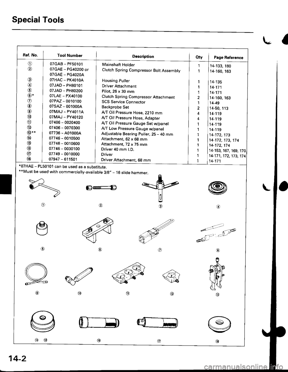
Special Tools
l.- a
Ref. No. Tool Number
o,6'\
€)
@)
@-
@
@
o
@
@
@
@..
@
@
@
@
@
07GAB - PF50101
07GAE - PG40200 or
OTGAE - PG4O2OA
07HAC - PK4010A
07JAD - PH80101
07JAD - PH80200
07LAE - PX40100
07PM - 0010100
07sM - 0010004
OTMAJ - PY4O1 1A
07MAJ - PY40120
07406 - 0020400
07406 - 0070300
07736 - A010004
07746 - 0010500
07746 - 0010600
07746 - 0030100
07749 - 0010000
07947 - 611501
Mainshaft Holder
Clutch Spring Compressor Bolt Assembly
Housing Puller
Driver Attachment
Pilot, 26 x 30 mm
Clutch Spring Compresso. Attachmenr
SCS Service Connector
Backprobe Set
IVT Oil Pressure Hose, 2210 mmAy'T Oil Pressure Hose, Adapter
Ay'T Oil Pressure Gauge Set dpanelA,/T Low Pressure Gauge WpanelAdjustable Bearing Pulter, 25 - 40 mmAftachment, 62 x 68 mm
Aftachment, 72 x 75 mmDriver 40 mm l.D.
Driver
Driver Attachment, 68 mm
I
1
1
1
I
1,l
'l
1
I
1
1
14-133, 180
14-160, 163
14-135
14-171
14-'�t7'l
14-160, 163
14-49
14-50, 113
r4-119
14- 1 19
14-119'14-1 19
14-172,173
14-172,'t73,114
14-172,174
14-153, 167. 169, 170
1+17 1 , 17 2, 173, 17
14-'t7'l
4
w
@o
*07HAE - P150101 can be used as a substitute.**Must be used with commercially-available 3/8,, _ 16 slide
E-E
@
@@
hammer.
=k
lalg
€)
ry
o
e
@
o
----a\\<-t-'- /\26
@@
@@@
aL
14-2
Page 719 of 2189
SERVICE CHECK CONNECTOR
LOCK -UP CONTROLSOLENOIO VALVEASSEMELY
RED WHT
tlll'
IT
tl
ll
Lo-l
MAINSHAFTSPEED SENSOR
TBRNiBLK
I
I
I-
G 101
NCSG ILS - ILS + ISH A ISH B ltc A ltc B
SHIF'CONTROLSOTENOID VALVEASSEMEI-Y
PCM Terminel Locations
14-41
Page 720 of 2189
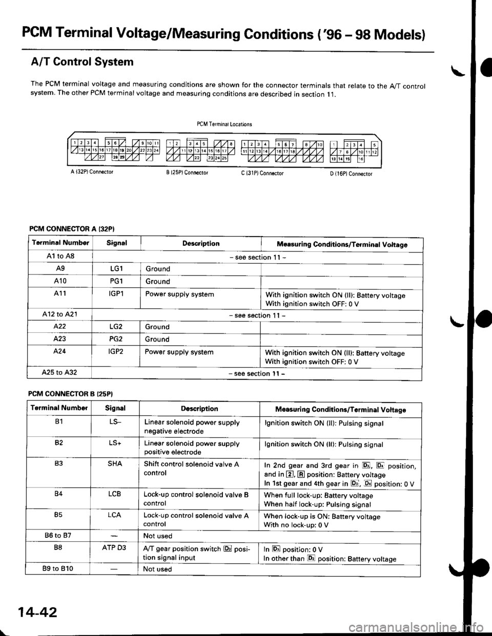
PCM Terminal Voltage/Measuring Gonditions ('96 - 9g Models)
A/T Control System
The PCM terminal voltage and measuring conditions are shown for the connector terminals that relate to the A"/T controlsystem. The other PCM terminal voltage and measuring conditions are described in section I l.
A l32P) Conn€ctotB I25P) ConnectorC (31P)ConngctorD (16P)Connector
PCM CONNECTOR A I32P}
Terminal NumborSignalDcacriptionMoasuring Conditions/Te.minal Voltage
A1 to A8- see section 1 I -
A9LG1Ground
A10PG1Grou nd
A11IGPlPower supply systemWith ignition switch ON (ll): 8attery voltage
With ignition switch OFF: 0 V
412 to A2l- see section I I -
Ground
423PG2Ground
A'24IG P2Power supply systemWith ignition switch ON (ll): Battery voltage
With ignition switch OFF: 0 V
A25 to A32- see section l1 -
PCM CONNECTOR B (25P}
Terminal NumberSignalDescriptionMeasuring Conditions/T6rminal Voltage
B1LS-Linear solenoid power supply
negative electrode
lgnition switch ON (ll): Pulsing signa.
82Linear solenoid power supplypositive electrode
lgnition switch ON (ll): Pulsing signal
SHAShitt control solenoid valve A
controlIn 2nd gear and 3rd gear in E, E position,
and in @, @ position: Battery voltage
In lst gear and 4th gear in E. E position: 0 V
B4LCBLock-up control solenoid valve B
control
When full lock-up: Battery voltage
When half lock-up: Pulsing signal
B5LCALock-up control sol€noid valve AcontrolWhen lock-up is ON: Battery voltage
With no lock-up: 0 V
86 to 87Not used
B8ATP D3IVT g6ar position switch @ posi-
tion signal input
lnEposition; OV
In other than E position: Battery voltage
Bg to 810Not used
\-
14-42
Page 721 of 2189
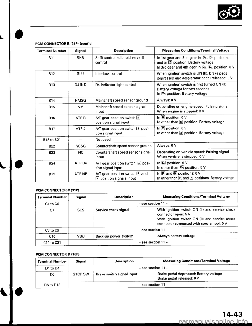
I
PCM CONNECTOR B {25P1 {cont'dl
Terminal NumberSignalDescriptionMeasuring Conditions/Terminal Vohage
811SHBShift control solenoid valve B
control
In 1st gear and 2nd gear in -q1, q11 position,
and in E] position: Battery voltage
In 3rd gear and 4th gear in lD.J, [Dr- position: 0 V
B't2SLUInterlock controlWhen ignition switch is ON (ll), brake pedal
deoressed and accelerator Dedal released: 0 V
813D4 INDD4 Indicator light controlWhen ignition switch is first turned ON (ll):
Battery voltage for two seconds
In E position: Baftery voltage
B't 4NMSGMainshaft speed sensor groundAlways: 0 V
E tcNMMainshaft speed sensor signal
input
Depending on engine speed: Pulsing signal
When engine is stopped: 0 V
816ATP RAy'T gear position switch Eposition signal input
InE position: 0V
In other than E position: Battery voltage
817ATP 2A/T gear position switch E posi-
tion signal input
InE position: 0V
In orher than E position: Battery voltage
818 to 821Not used
s22NCSGCountershatt speed sensor groundAlwaysr 0 V
B�23NCCountershaft speed sensor signal
input
Depending on vehicle speed: Pulsing signal
When vehicle is stopped: 0 V
B�24ATP D4Ay'T gear position switch lor posi-
tion signal input
InEposition:0V
In other than 6 position: 5 V
ATP NPA,/T gear position switch E and
N position signals input
InE and E positions: 0V
In otherthan E and N] positions: Battery voltage
PCM CONNECTOR C {31P)
Terminal NumberSignalDescriptionMeasuring Conditions/Terminal Voltage
Cl to C6- see section 11 -
c1Service check signalWith ignition switch ON (ll) and service check
connector oDen; 5 V
With ignition switch ON (ll) and service check
connector connected with sDecial tool: 0 V
C8 to Cg- see section 11 -
c10VBUBack-up power systemAlways battery voltage
C11 to C31- see section '11 -
PCM CONNECTOR D (16P}
Terminal NumberSignalDescriptionMeasuring Conditions/Terminal Voltage
Dl to D4- see section 11 -
D5STOP SWBrake switch signal inputBrake pedal depressed: Battery voltage
Brake pedal released: 0 V
D6 to D16- see section 1 l -
14-43