Page 521 of 2189

Emission Gontrol System
System Description
The emission control system includes a Three Way Cata-lytic Convener (TWC), Exhaust Gas Recirculation (EGR)
system,. Positive Crankcase Ventilation (pCV) system andEvaporative Emission (EVAP) Control system. The emis-sion control system is designed to meet federal and stateemission standards.*: D16Y5 engine
Tailpipe Emission
Inspestion
@@ Do not smoke during ihis procedure. Keepany open flame away from your work area.
1. Start the engine. Hold the engine at 3,000 rpm withno load (in Park or neutral) until the radiator fancomes on. then let it idle.
2. Connect a tachometer.
Check and, if necessary, adjust the idle speed (see
page 11-220 - 223).
Warm up and calibrate the CO meter according to themeter manufacturer's instructions.
Check idle CO with the headlights, heater blower,rear window defogger, cooling fan, and air condition-er off.
NOTE: (Canada) Pull the parking brake lever up.Start the engine, then check that the headlights areoff.
CO mete. should indicate 0.1% maximum.
NOTE: '98 Dl6Y5 engine - lf the idle speed incress-es to 8101 50 rpm, this means the EVAp system ispurging the canister. To stop the purging temporari-ly. raise the engine speed above 1,000 rpm with theaccelerator pedal, then slowly release the pedal.
11-252
eFORWARD -
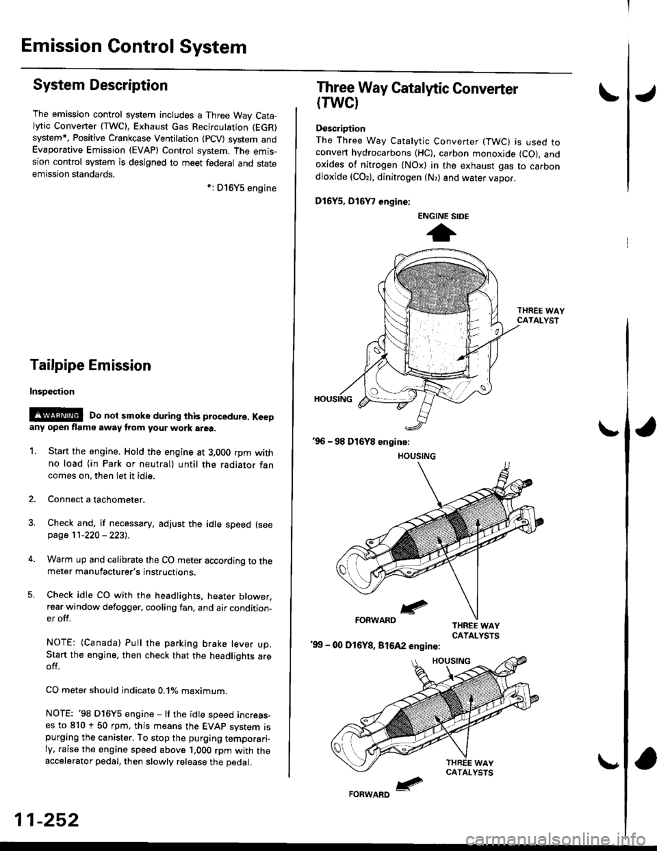
Three Way Catalytic Converter
(TWCI
Doscription
The Three Way Catalytic Converter (TWC) is used toconven hydrocarbons (HC), carbon monoxide (CO), andoxides of nitrogen (NOx) in the exhaust gas to carbondioxide (COr), dinitrogen (N,) and water vapor.
D15Y5, D16
, engine:
'99 - 00 D16Y8, 81642 engine:
ENGINE SIDE
t
Page 525 of 2189

Emission Control System
Exhaust Gas Recirculation (EGR) System (D16Y5 engine with GWI (cont'dl
lTl49il T_he scan tool indicates Diagnostic Trouble Code (OTC) P1491: A malfunction in the Exhaust Gas Recirculation- lEgh) svstem.
CvT lM/T see page 1l-2611:
J
EGR VALVELIFT SENSOR#16 HOSE
PUMP/GAUGE,0- 30 in.HsA973X-041-XXXXX
EGRVALVE
The MIL has been reoorted on.DTC P1491 is stoled.
Problem verification:1. Do the ECM/PCM Reset Proce-du re.2. Connect the SCS service con'
3. Start the engine. Hold theengine at 3,000 rpm with noload {in Park or neutral) untilthe radiator fan comes on,4. Drive the vehicle on the roadfor approx. 10 minutes. Try tokeep the engine speed in the1,700 - 2,500 rpm range.
Intermittonl failure, system is OKat this time. Check for Door con-nections or loose wires at, C144{EGR velve} and ECM/PCM.
ls DTC P l49l indicated?
Check fo. vacuum to ihe EGR
1. Disconnect the No. 16 hose fromthe EGR valve.2. Connect a vacuum pump/gauge to the hose.3. Start the engine and let it idle.
ls there any vacuum?
Check tor a malfunction in theEGR control solenoid valve:'1. Disconnect the EGR controlsolenoid valve 2P connector,2. Becheck the No. 16 hose for
Check vacuum hose routing o,the entire EGR svstem. lf hoserouting is OK, replac€ the EGRcontrol solenoidvalv6.
ls there any vacuum?
Substitute a known-good ECM/PCM and recheck. It symptom/indicalion goes away, replacethe original ECM/PCM.
(To page 11 257)
11-256
Page 526 of 2189
![HONDA CIVIC 1996 6.G Workshop Manual \EGR VALVELIFT SENSOR#16 HOSE
I
(From page 11-256)
EGR VALVE LIFT SENSOR3P CONNECTOR lC14.l)
zF vcczI- . ] IYEL/BLU)ll 2l3l---l-r_ 7 |
v-,, ISG2IGRN/BLK) I ^ II{Vts
ECM CONNECTOR D {16P)
PUMP/GAUGE,0 HONDA CIVIC 1996 6.G Workshop Manual \EGR VALVELIFT SENSOR#16 HOSE
I
(From page 11-256)
EGR VALVE LIFT SENSOR3P CONNECTOR lC14.l)
zF vcczI- . ] IYEL/BLU)ll 2l3l---l-r_ 7 |
v-,, ISG2IGRN/BLK) I ^ II{Vts
ECM CONNECTOR D {16P)
PUMP/GAUGE,0](/manual-img/13/6068/w960_6068-525.png)
\EGR VALVELIFT SENSOR#16 HOSE
I
(From page 11-256)
EGR VALVE LIFT SENSOR3P CONNECTOR lC14.l)
zF vcczI- . ] IYEL/BLU)ll 2l3l---l-r_ 7 |
v-,, ISG2IGRN/BLK) I ^ II{Vts
ECM CONNECTOR D {16P)
PUMP/GAUGE,0 - 30 in.Hs4973X-041-XXXXX
sG2(GRN/BLKIvcc2IYEL/BLU}
Wire side ol temale terminals
PCM CONNECTORS C (31P}'
YES
Wire side of female terminals
1
(cont'd)
1-257
Check fo. a mallunction in theEGF valv€:1. ldove the vacuum pump/gauge
to the EGR valve.2. With the engine at idle, apply
26.7 kPa (200 mmHg,8.0 in.Hg)
ofvacuum to the EGR valve.
Does the engine stall or runrough and does the EGR valvehold vacuum?
Check for an open in the wire
IVCC2linel:1. Turn the ignition switch OFF.2. Disconnect the EGR valve liftsensor 3P connector.3. Turn the ignition switch ON (ll).
4. Measure voltage between theEGR valve lift sensor 3P con'
nector terminals No. 3 and
No.2.
ls lhere approx.5 V?
Check for an oDen in the wire
{VCC2 line}:Measure voltage between theECM/PCM connector terminalsD10 and Dl1 (C18 and C28)*.
Rep.ir open in the wire betweenrhe EGR valve snd ECM/PCM
{Dl0 {C28)*).lsthere approx.5 V?
Sub3titute t known-good ECM/PCM end recheck. lt 3ymptom/indication goos eway, replaceth6 original ECM/PCM.(To page 1l-258)*: '99 - 00 models
Page 527 of 2189

Emission Gontrol System
Exhaust Gas Recirculation (EGRI System (Dl6Y5 engine with CW) (cont'dl
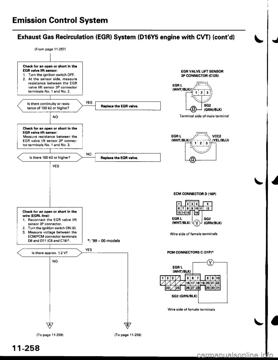
EGR VALVE LIFT SENSOR3P CONNECTOR {Cl251
./
EGR L(WHT/BLKI
EGR LIWHT/BLKI
EGR L{WHT/BLKI
sG2
{GRN/BLK}
sG2{GRN/BLK}
Terminal side ol male terminal
ECIT'I CONNECTOR D II6PI
Wir€ side of f€male terminals
PCM CONNECTORS C (31PI*
{To page 11-259)
11-258
{From page 11-257}
Chock lor an opcn or short in th.EGR v.lve lift .€nsor'1. Turn the ignition switch OFF.2. At the sensor sid€, measur€resistance between the EGRvalve lift sensor 3P connectorterminals No. 1 and No.2.
ls there continuity or resis'tance ot 100 k0 or higher?
Chock tor sn op€n or lhort in theEGR valve lift lonror:Measure resistancg between theEGR valve lift s€nsor 3P connec-tor terminals No. 1 and No. 3.
ls there 100 k0 or higher?
Ch.ck tor an ooon or rhon in thcwiro IEGRL linc):1. Beconnect tho EGR v6lve liftsensor 3P connector.2. Turn tho ignition switch ON (ll).
3. Measure voltage between theECM/PCM connector terminalsD9 and Dl1 (C6 and C18l*.
ls there approx. 1.2 V?
(To page 11-259)
Wire side of female terminals
Page 528 of 2189

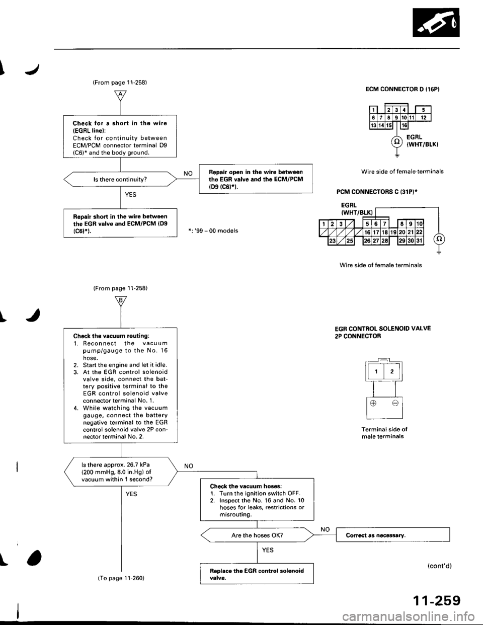
I
I
Wire side of lemale terminals
PCM CONNECTORS C (31P)*
ECM CONNECTOR O {I5PI
Wire side of temale terminals
t
(From page 11-258)
Check for a 3hort in the wire
{EGRL linel:Check for continuity betweenECM/PCM connector terminal Dg
Repair op€n in the wire betweenth6 EGR valve and the ECM/PCM(D9 tc6trt.
ReDair short in the wirc batweonthe EGR valve and ECM/PCM {Og(c5t*).
(From page 11-258)
11,260)
Check ths vacuum routing:'1. Recon nect the vacuumpump/gauge to the No. 16hose.2. Start the engine and let it idle.3. At the EGR control solenoidvalve side, connect the bat-tery positive terminal to theEGR control solenoid valveconnectot terminal No. 1.4. While watching the vacuumgauge, connect the batterynegative terminal to the EGRcontrol solenoid valve 2P con-nector terminal No. 2,
ls there approx.26.7 kPa
1200 mmHg,8.0 in.Hg) ofvacuum within 'l second?Chock the vlcuum hos6s:1. Turn the ignition switch OFF.2. Inspect the No. 16 and No. 10hoses for leaks, restrictions ormtsrouUng.
EGR CONTROL SOLENOID VALVE
2P CONNECTOR
Terminal side oImale lerminals
(cont'd)
11-259
Page 529 of 2189

Emission Control System
Exhaust Gas Recirculation (EGR) System (Dl6Y5 engine with CW) (cont'dl
tJ
(From page 11-259)EGR CONTROL SOLENOIDVALVE 2P CONNECTOR {C142}
Wire sideof lemaleterminals
ECMCONNECTORa t32Pl
Chock lor an open in the wire (E
SOL linsl:1. Turn the ignition switch OFF.2. Disconnect the 2P connectorIrom the EGR control solenoid
3. Disconnect the ECN4/PCM con-nector A (32P) (B (25P))* fromthe EcM/PCM.4. Check tor continuity betweenECM/PCl, connector terminal47 (86)* and the EGR controlsolenoid valve 2P connectorterminal No.2.
Repair opon in th. wir. bstwocntha EGR control 3ol€noid valvoand tho ECM/PCM (A7 186l'1.
ls there continuity?
Check for . rhort in the wire(ESOL linel:Check for continuity between theEGR controlsolenoid valve 2P con-nector terminal No. 2 and bodyground,
R.p.ir ahort in tha wi.c b.twecnthe EGR control iolonoid vllyeand th. ECM/FCM {A7 (46}rl.
Check for an opon in the wiroIGND linel:Check for continuity between theEGR controlsolenoid vaive 2P con-nector terminal No. I and bodyground,
Rcpai. op€n in the wir6 b6'twoenthe EGR control rol.noid valveand G101.
Sub3titule a known-good ECM/PCM and rechock. lf symptom/indication goes away, replac€the original ECM/PCM.
ESOL
IRED)
ESOLIRED)
Wire sideof femaleterminals--_-]
I
EGR CONTROL SOLENOIDVALVE 2P CONNECTOR ICl'2}
Wire sideof femaleilterminals
ECMCONNECTORB l25P)ESOL(REDI
Wire sideof femalerermtnats
*: '99 - 00 models
11-260
Page 530 of 2189

\JExhaust Gas Recirculation System (D16Y5 engine with M/T)
M/T:
EGR VALVE 6P CONNECTOB (C14'rl
G10lIBLK}
1
a
PNK
IE.EGRI
Wi16 side of male terminals
I
sG2{GRN/BLK}
vcc2{YEL/BLU)
- Th6 MIL ha3 b€on reponed on.- DTC Pl,{tl is 3tored.
Prcblem verification:1. Do the ECM Reset Procedure.
2. Connect the SCS service con_nector.3. Start the engine. Hold the
engine at 3,000 rpm with no
load (transmission in neutral)
untilthe radiator fan comes on.
4. Drive the vehicle on the road
for approx. 10 minutes. Try to
keep the engine speed in the
1,700 - 2,500 rpm range.
lnlermittont tailure, svalem is OK
at thi3 tim6. Check foi Poor con'
nections or looso wiro3 at Cl/K
IEGR valvsl and ECM.
ls DTC P1491 indicated?
Check tor a malfunction in the
EGR valv6:1. Turn the ignition switch OFF.
2. Disconnect the EGR valve 6P
connector.3. Stanthe engine and let it idle
4. Measure voltage between the
EGR valve 6P connector termi'
nals No.4and No.6.
Check the EGR valve:1. Turn the ignition switch OFF2. Turn the ignition switch ON lll).3. Measure voltage between theEGR valve 6P connector termi
nals No.2 and No.3.
ls there battery voltage?
Substitute a known-good ECM
and recheck. It symptom/indica_tion goes away, replace th€ origi-
nal ECM.
ls there approx.5V?
(To page 11-262)
Page 531 of 2189
Emission Control System
(From page 11-261)
Check tor open in the wire (SG2
linel:Measure voltage between theECM connector terminals D10and D11.
Repsir open in lhe wire beiweenECM lOllland EGR valve.ls there approx. 5 V?
Check the EGR valve:1. Turn the ignition switch OFF.2, At the sensor side, measureresistance between the EGRvalve 6P connector terminalsNo. 1 and No. 2.
ls there continuity or resis-tance of 100 k0 or higher?
Check the EGR valve:Measure resistance between theEGR valve 6P connector terminals No. 1 and No.3.
ls there 100 k0 or higher?
Exhaust Gas Recirculation System (D16Y5 engine with M/T) (cont'dl
ECM CONNECTOR D {16P)
vcc2(YEL/BLU)
\v
sG2IGRN/BLK)
Wire side of female term;nals
EGR VALVE 6P CONNECTOR
EGR L(WHT/
BLK}
SG2 (GRN/BLK)
Termanal side of male terminals'l'
EGR L{WHT/BLK}
vcc2
{YEL/BLU}
(To pase 11 263)
1-262