Page 2072 of 2189
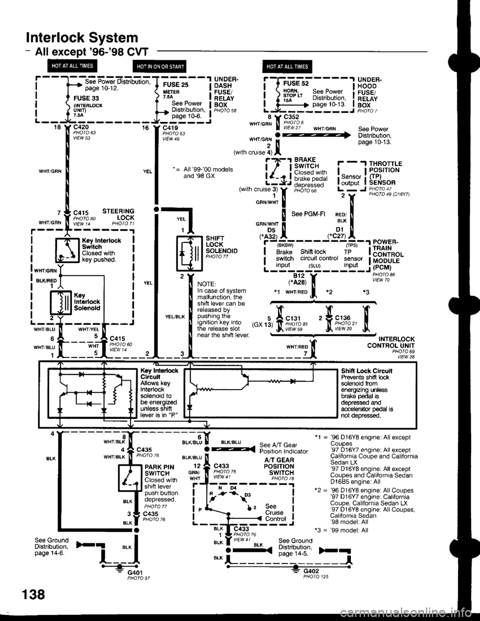
lnterlock System
- Allexcept'96-'98 CVT
page 10-12.
FUSE 33{INTEBLCICKuNrI)
WHIICRN
OASH I HOOD
H:" - IlEiE" i ) iifl* 8i?[',ffii i[".tfi
;GE-st----l glD^:R-
page 10-13. I BoxL.J------ --J PHotoi
*1 = 96 D16Y8 engine: Allexceptuoupes'97 D16Y7 engine: All exceptCalifornia Coupe and CaliforniaSedan LX'97 D16Y8 engine: All exceptCoupes and Calilornia SedanD1685 engine: All*2 = '96 D16Y8 engine: AllCoupes'97 D16Y7 engine: CaliforniaCoupe, California Sedan LX'97 D16Y8 englne: AllCoupes,Calilornia Sedan'98 model: All*3 = '99 model: All
)rq
,'",:[*nu'
=-CF'!,n:E!-l
Hfl*gff* i
l#?;"'" -,,;:::?i-ili:itlll:
|
= lr.u:;.Br-* i-{Ji6i1!-- !,*;L$il{:*
|
,wrn cruse;r
tr,
;"6;dii-- Lr7 r ii\l,B".i o,",,,
i-l o,"*",!
'""'o*-'' x?!
| -$-.",., .^AX-----.,'dtA--"^",."
lfl.iil F]iH*,"'i''t#'---.r=23[11
eowen.
lElJP-".'.'
-
L;tT'#:yTltijF.iu.'f, *or., ,.il3, f, iii"^'?o'
| !^:?::^?l:t:9" *r w'raeof, *2 *3
t:l*ii** ffi"""'"
! fit:'/:,:iffJff ,",'3,fii;1,1,'' 'trii'df,'
tr
I near lne snrn rever - TNTERLOCK
ll wxrneo t CONTROL UNIT
--4-------------Lt, *?,1fl92
T-----1 UNDER-FUSE 25
See Power I BOtDisilibution, : pHb'ro ss
.----
page 10-6. I 8 i, C352-----J' c419""'''A\Fi#"i: wHr/cRN see power
'[il:'ff*,,,,**
., J*:]l ., '"*""
;.-9,[ aL(BLU
GFN/
I
See A/T GearPosition Indicator
A/T GEARPOSITIONswtTcHc433
BLK I-
i-*t'
BLK1BLK
f, 9e€urutse
I
I
I
IControl
ilt:tfi'F1
'-i_:{BLKO-<(
See GroundDistribution,page 14-5.
-l#: G401PHO|O 57
Key IntedockClrcuitAllows keyint€rlocksolenoid tobe energizedunless shiftlever is in "P"
Shltt Lock ChcuilPrevents shifi bcksolenoid tromenergizing unlessbrake p€dal isd€pfessed ardacc€le{ator pedal isnot depr€ssed.
";t-,".f";,
138
Page 2110 of 2189
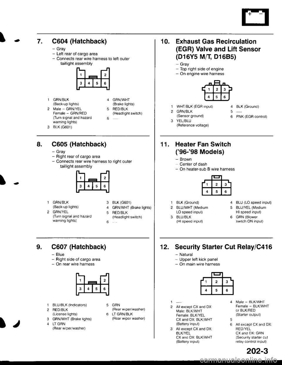
\7. C604 (Hatchback)
GRN/BLK(Back-up lights)
l\4ale GRNIYELFemale - GRN/RED(Turn signaland hazardwarning lights)
BLK (G601)
- Gray- Left rear ol cargo area- Connects rear wire harness to left outer
taillight assembly
4
5
6
1
2
GRNAVHT(Brake lights)
FED/BLK(Headllght switch)
10. Exhaust Gas Recirculation
(EGR) Valve and Lift Sensor
1
2
3
(D16Y5 MfI D1685)
- Gray- Top right side of engine- On engine wire harness
WHT/BLK (EGR input)
GRN/BLK(Sensor ground)
YEUBLU(Reference voltage)
4
5
6
BLK (Ground)
PNK (EGR control)
of cargo area
rear wire harness to right outer
assembly
n- -n
a t | _ a2a
l3I4t5tttl
IJ
I
8. C605 (Hatchback)
- Gray- Right rear- Connects
taillight
GRN/BLK(Back-up lights)
GRNTYEL(Turn signaland hazardwarning lights)
3
4
5
6
1
2
BLK (G601)
GFNAVHT (Brake lights)
RED/BLK(Headlight switch)
11. Heater Fan Switch
('96-'98 Models)
- Brown
Center of dash- On heater-sub B wire harness
BLK (Ground)
BLUAVHT (L4edium
LO speed input)
BLU/BLK(Hl speed input)
4
5
6
1
2
3
BLU (LO speed input)
BLU/YEL (Medium
Hlspeed input)
GFIN (Blowerswitch ON input)
9. C607 (Hatchback)
- Blue- Right side o{ cargo area- On rear wire harness
BLU/BLK (lndicators)
RED/BLK(License lights)
GBN,ryVHT (8rake lights)
LT GBN(Rear wiper/washe0
5
6
1
2
3
4
GRN(Rear wiper/washer)
LT GRN/BLK(Rear \/iper washer)
)/
202-3
12. Security Starter Cut Relay/C416
- Natural* Upper left kick panel- On main wire harness
1
2Allexcept CX and DXI[,4ale: BLK,^r'r'HTFemale: BLKI/ELCX and DXi BLI(WHT(Battery input)
All except CX and DX:BLK^/ELCX and DX: BLK/WHT(Baftery input)
[.4ale - BLK/WHTFemale - BLKAVHTor BLKRED(Starter output)
All excepi CX and DX:RED/YELCX and DX: GRN(Security starter c!1relay control inpul)
5
6
tl3'
Page 2112 of 2189
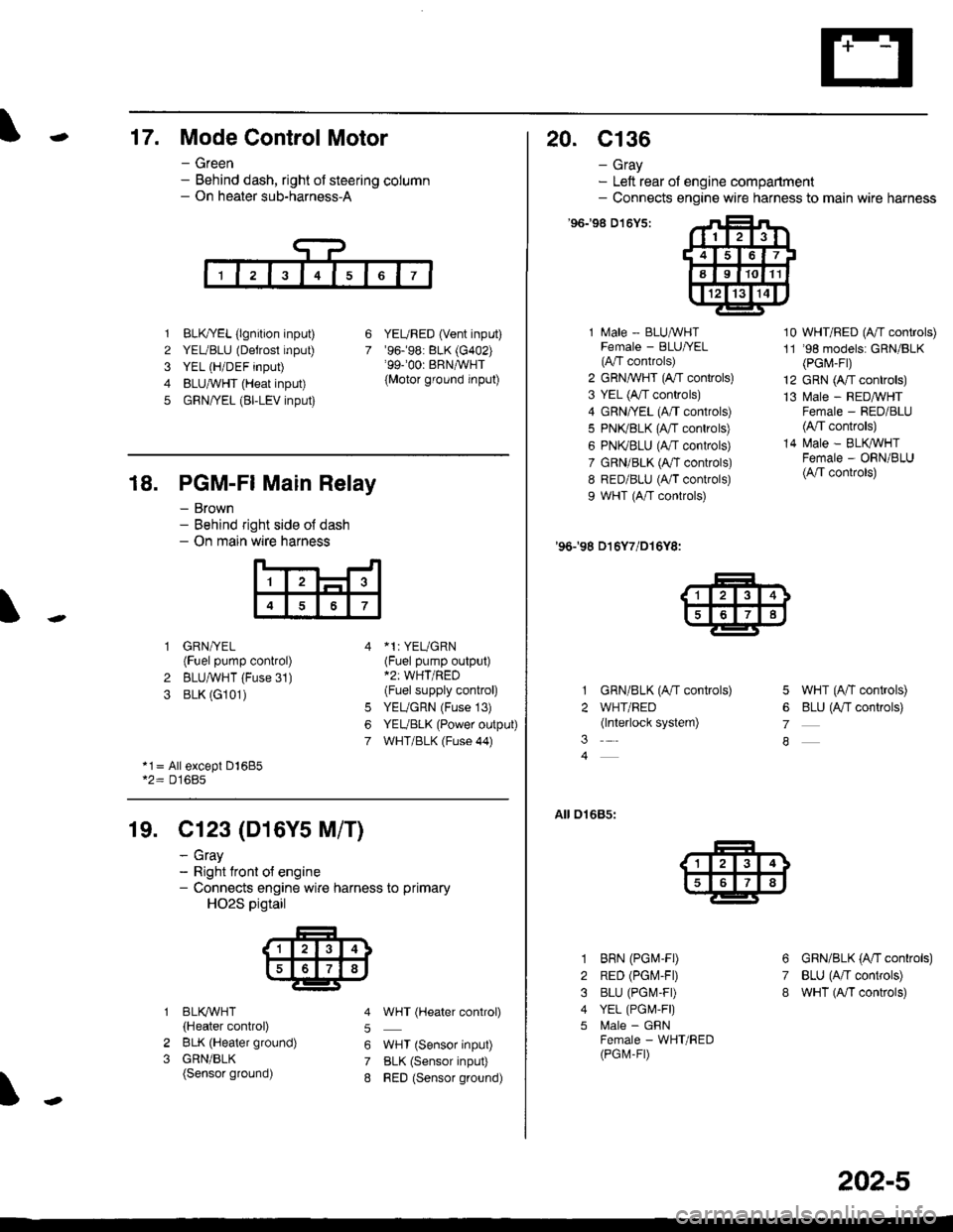
-17. Mode Control Motor
- Green- Behind dash, right of steering column- On heater sub-harness-A
1 BLK,TYEL (lgnition input)
2 YEUBLU (Detrost input)
3 YEL (H/DEF input)
4 BLUA/VHT (Heat input)
5 GRN/YEL (BI-LEV input)
YEURED (Vent input)'96.�98: BLK (G402)'99-'00r BRNAVHT
{Motor ground input)
6
7
18. PGM-FI Main Relay
- Brown- Behind right side o{ dash- On main wire harness
'l
4
1 GRN/YEL(Fuel pump control)
2 BLUAVHT (Fuse 31)
3 BLK (G101)
*1: YEUGRN(Fuel pump output)*2: WHT/RED(Fuel supply control)
YEUGRN (Fuse 13)
YEUBLK (Power output)
WHT/BLK (Fuse 44)
6
7
*1= All except Dl685*2= D16Bs
19. Cl23 (D16Y5 M/T)
2
3
BLI(WHT
{Heater control)
BLK (Heater ground)
GRN/BLK(Sensor ground)
- cray- Right tront o{ engine- Connects engine wire harness to primary
HO2S pigtail
5
6
7
8
WHT (Hgater control)
WHT (Sensor input)
BLK (Sensor input)
RED (Sensor ground)
20. c136
- Gray- Left rear of engine compartment- Connects engine wire harness to main wire harness
'96198 D't6Y5:
1 Male - BLUAVHTFemale - BLU|/EL(A"/T controls)
2 GRN,^WHT (A,/T controls)
3 YEL (A/T controls)
4 GRN/YEL (A/T controls)
5 PN(BLK (fff gs6lrq;s;
6 PNI(BLU (A/T controls)
7 GRN/BLK (Ar/T controls)
8 RED/BLU (A/T controls)
9 WHT (A/T controls)
'96198 D16Y7/D16Y8:
GRN/BLK (A/T controls)
WHT/RED(lnterlock system)
10 WHT/RED (A"/T controls)
11 '98 models: GRN/BLK(PGr,4-Fr)
12 GRN (A/T controls)
13 l\4ale - REDMHTFemale - RED/BLU(4,/T controls)
14 N4ale - BLIVWHTFemale - ORN/BLU(A/T controls)
5 WHT (A/T controls)
6 BLU (Antf se11re;s;
7
A
01685:
3
1
2
3
4
5
6
7
8
BRN (PGM-FD
RED (PGIV-FD
BLU (PGI\4-FD
YEL (PGI,4,F|)
l\4ale - GFNFemale - WHT/RED(PGM-FD
GRN/BLK (A'tl gs6trels;
BLU (A/T controls)
wHT (A/I controls)
202-5
Page 2113 of 2189
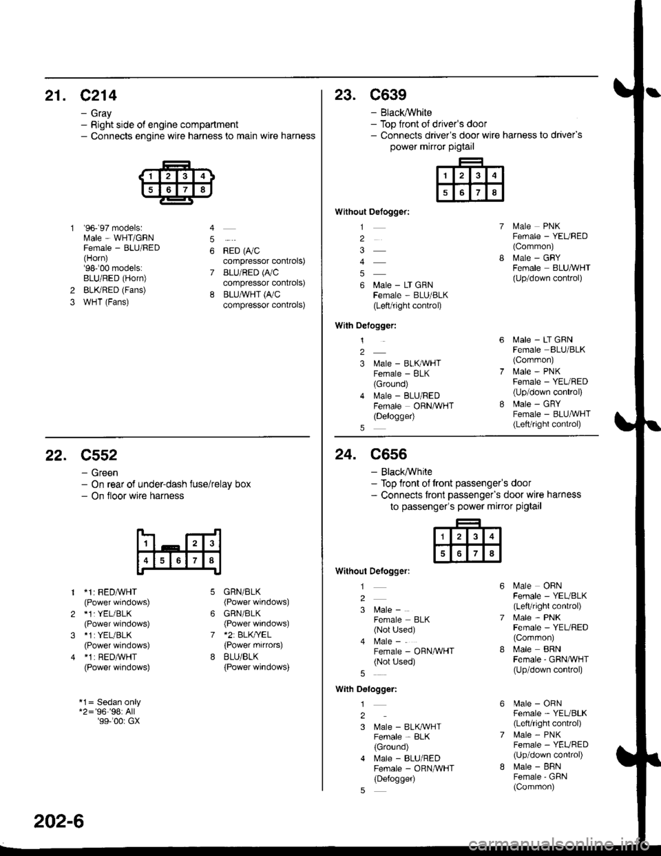
21. C214
- Gray- Right side of engine compartment- Connects engine wire harness to main wire harness
'96- 97 models:Male - WHT/GRNFemale - BLU/FED(Horn)'98-'00 models:BLU/RED (Horn)
BLKRED (Fans)
WHT (Fans)
4
5
6
7
*io t0,,"compressor controls)
BLU/RED (A,/C
compressor controls)
BLU,ryVHT (I'/C
compressor controls)
2
3
23. C639
- Black,ryVhite- Top front ot driver's door- Connects driver's door wire harness to driver's
power mirror pigtail
Without Defogger:
1
2
4
6 Male - LT GRNFema|e - BLU/BLK(Left/right control)
With Oelogger:
1
2
3 l\,lale - BLKAVHTFemale - BLK(Ground)
4 lvlale - BLU/REDFemale ORNAVHT(Delogge4
lvlale PNKFemale - YEURED(Common)
MaIe _ GRYFemale BLUA/VHT(Up/down control)
lvlale - LT GRNFemale BLU/BLK(Corrmon)
i.4ale - PNKFemale - YEURED(Up/down conkol)
Male - GRYFemale - BLU,ryVHT(Lett/right control)
22. C552
- Green- On rear of under-dash fuse/relay box- On tloor wire harness
1 *1: FEDA/VHT(Power windows)
2 *1: YEL/BLK(Power windows)
3 *1:YEL/BLK
(Power windows)
4 *1 | RED/WHT(Power windows)
*1= Sedan only*2='96''98:All'99-'00r GX
6
7
GRN/BLK(Power windows)
GRN/BLK(Power windows)*2: BLK/YEL(Power mifiors)
BLU/BLK
{Power windows)
202-6
24. C556
- Black,ryVhite- Top front of front passenger's door- Connects tront passengefs door wire harness
to passenger's power mirror pigtail
Without Defogger:
l
2
3 l\4ale -
Female BLK(Not Used)
4 l\4ale -
Female - ORN/WHT(Not Used)
With Delogger:
1
2
3 Male - BLK^VHTFemale - BLK(Ground)
4 l\.4ale - BLU/REDFemale - ORNAVHT(Defogger)
Male OBNFemale - YEUBLK(LefVright control)
l\4ale - PNKFemale - YEL/RED(Common)
Male BRNFemale - GRNA/VHT(Up/down conkol)
[.4ale - ORNFemale - YEL/BLK(Left/right control)
lrale - PNKFemale - YEURED(Up/down conkol)
l\,lale - BFNFemale'GFiN(Common)
Page 2115 of 2189
Connector Views (cont'd)
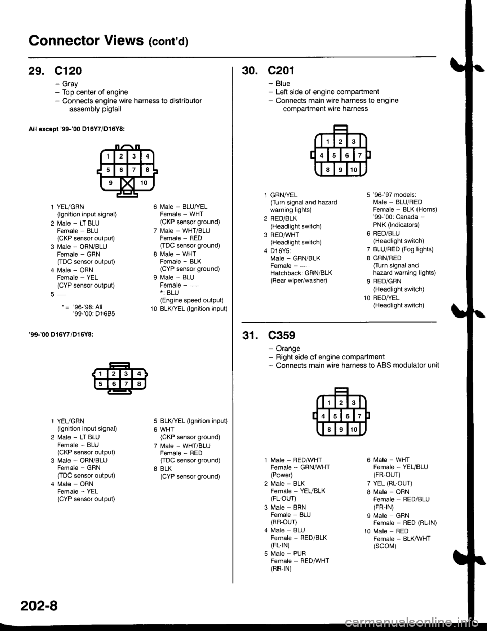
29. C120
- Gray- Top center of engine- Connects engine wire harness to distributor
assembly pigtail
All except '99-'00 016Y7/D16Y8:
l YEUGRN(lgnition input signal)
2 l\.4ale - LT BLUFemale - BLU(CKP sensor output)
3 Male - ORN/BLUFemale - GRN
[tDC sensor output)
4 l\.4ale - ORNFemale - YEL(CYP sensor output)
-= '96j98: All'99100: D1685
'99-'00 016Y7/D16Y8:
l YEUGRN(lgnition input signal)
2 Male - LT BLUFemale - BLU(CKP sensor output)
3 Male - ORN/BLUFemale - GRN
CIDC sensor output)
4 Male - ORNFemale - YEL
{CYP sensor output)
l\4ale - BLU/YELFemale - WHT(CKP sensor ground)
l\.4ale - WHT/BLUFCMAIE _ HtsL'(TDC sensor ground)
l\4ale - WHTFemale - BLK(CYP sensor ground)
Male - BLUFemale - . -*: BLU(Engine speed output)
BLK/YEL (lgnition input)
BLK/YEL (lgnition input)
WHT(CKP sensor ground)
Male - WHT/BLUFemale - RED
ffDC sensor ground)
BLK(CYP sensor ground)
10
202-8
30. c201
- Blue- Left side of engine compartment- Connects main wire harness to engine
compartment wire harness
l GRNA/EL(Turn signal and hazardwarning lights)
2 RED/BLK(Headlight switch)
3 REDAVHT(Headlight switch)
4 D16Y5:Male - GRN/BLKFemale -
Hatchbacki GRN/BLK
{Bear wipetwashe0
7
I
9b- 9/ mooets:lvlale - BLU/REDFemale BLK (Horns)'99-'00: Canada -
PNK (lndicators)
RED/BLU(Headlight switch)
BLU/RED (Fog lights)
GRN/RED
Cturn signal andhazard warning lights)
BED/GRN(Headlight switch)
RED/YEL(Headlight switch)
31. C359
- Orange- Right side ot engine compartment- Connects main wire harness to ABS modulator unit
10
l\4ale - REDAVHTFemale - GRNA/VHT(Power)
l\,4ale - BLKFemale - YEVBLK(FL-OUr)
Male - 8RNFemale BLIJ
{RR-OLrr)l\4ale BLUFemale - RED/BLK(FL-rN)
Male - PURFemale - RED&VHT(RR-rN)
6 Male - WHTFemale - YEUBLU(FR-OUr)
7 YEL (RL-OUr)
I Male - ORNFemale - RED/BLU(FR rN)
I Male GRNFemale - RED (RL-|N)
10 Male REDFemale - BLK,ryVHT(scol\,1)
Page 2117 of 2189
Connector Views (cont'd)
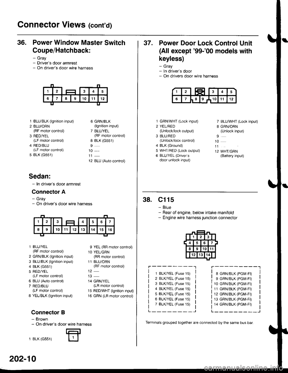
36. Power Window Master Switch
Coupe/Hatchback:
- Gray- Driver's door armrest- On driver's door wire harness
3
5
BLU/BLK (lgnition input)
BLU/ORN(RF motor control)
RED/YEL(LF motor control)
FED/BLU(LF motor control)
BLK (G551)
6 GRN/BLK(lgnition input)
7 BLU/YEL(RF motor control)
8 BLK (G551)
10
12 BLU (Auto control)
I YEL (RR motor control)
1O YEUGRN(RR motor control)
11 BLU/ORN(RF motor control)
14 GRN/YEL(LR motor control)
15 REDMHT (lgnition input)
16 GRN (LR motor control)
Sedan:
- In driver's door armrest
Connector A
- Gray- On driver's door wire harness
l BLU/YEL(RF motor control)
2 GRN/BLK (lgnition input)
3 BLU/BLK (lgnition input)
4 BLK (G551)
5 RED/YEL(LF motor control)
6 8LU (Auto control)
7 RED/BLU(LF motor control)
8 YEUBLK (lgnition input)
Connector B
- Brown- On driver's
1 BLK (Gss1)
door wire harness
E
202-10
Terminals grouped together are connected by the same bus bar
37. Power Door Lock Control Unit
(All except'99-'00 models with
keyless)
- Gray- In driver's door- On drivers door wire harness
1 GRNMHT (Lock input)
2 YEURED(Unlock/lock output)
3 BLU/RED(unlock/lock control)
4 BLK {Ground)5 WHT/RED (Lock output)
6 BLU/YEL (Drivefs
door unlock input)
7 BLU/WHT (Lock input)
B GRN/ORN(Unlock input)
10
11
12 WHT/GRN(Battery input)
38. Cl15
- Blue- Rear of engine, below intake manifold- Engine wire harness junction connector
r----------lr---------"1
1 8LK?ryEL (Fuse 15)
2 BLK/YEL (Fuse 15)
3 BLK TEL (Fuse 15)
4 BLK/YEL (Fuse 15)
5 BLK,/YEL (Fuse 15)
6 BLK/YEL (Fuse 15)
7 BLK,TYEL (Fuse 15)
8 GRN/8LK (PGM FD
9 GRN/BLK (PGM.FD
10 GRN/BLK (PGr\,4-Fr)
11 GBN/BLK (PGM-Fr)
12 GRN/BLK (PGM-FD
13 GRN/BLK (PGM-FD
14 GRN/BLK (PGM-Fr)
L_______-JL______--_J
Page 2141 of 2189
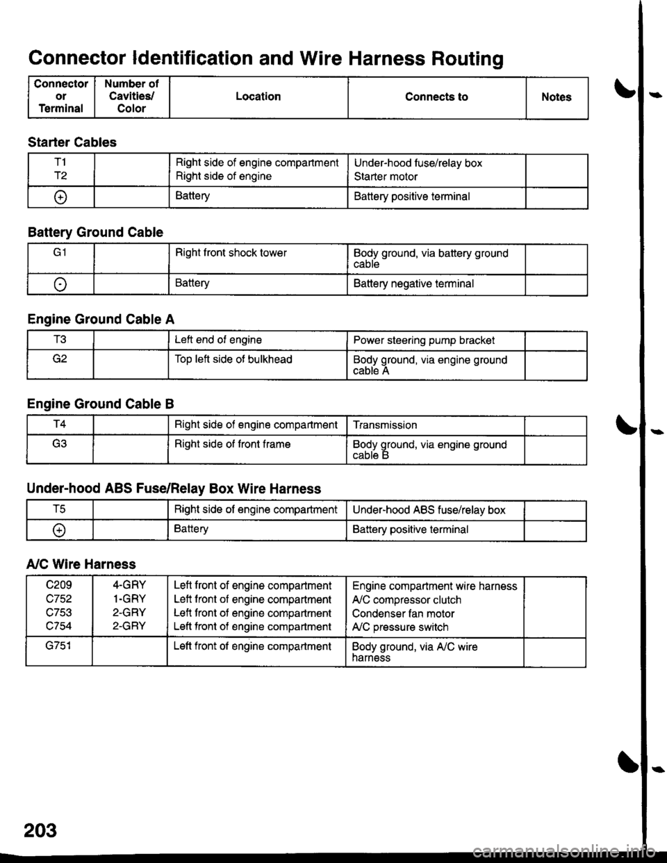
Connector ldentification and Wire Harness Routing
Connector
or
Terminal
Number of
Cavities/
Color
LocationConnects toNotes
Starter Cables
T1
r2
Right side of engine compartment
Right side of engine
Under-hood luse/relay box
Staner motor
t+lBatteryBattery positive terminal
Battery Ground Cable
Right front shock towerBody ground, via battery ground
cable
oBatteryBattery negative terminal
Engine Ground Cable A
t!tLeft end of enginePower steering pump bracket
Too left side ot bulkheadBody ground, via engine ground
cable A
Engine Ground Cable B
T4Bight side of engine compartmentTransmission
(ritRight side of front frameBody ground, via engine ground
Under-hood ABS Fuse/Relay Box Wire Harness
tcRight side of engine compartmentUnder-hood ABS fuse/relay box
oBatteryBattery positive terminal
A,/C Wire Harness
c209
wtJl/,\-7Ee
c754
4-GRY
1.GRY
2-GRY
2-GRY
Lefl front of engine compartment
Left front of engine compartment
Lefl front of engine compartment
Left tront of engine compartment
Engine compartment wire harness
A,/C compressor clutch
Condenser fan motor
A,/C pressure switch
G751Left front of engine compartmentBody ground, via A,/C wireharness
Page 2142 of 2189
\..
STARTERCABLES
\..UNDER.HOODABS FUSE/RELAYBOX WIREHARNESS
BATTERYGROUNDcAELE
ENGINEGROUNDCAELE BA/C WIREHARNESS
)-
203-1