Page 906 of 2189

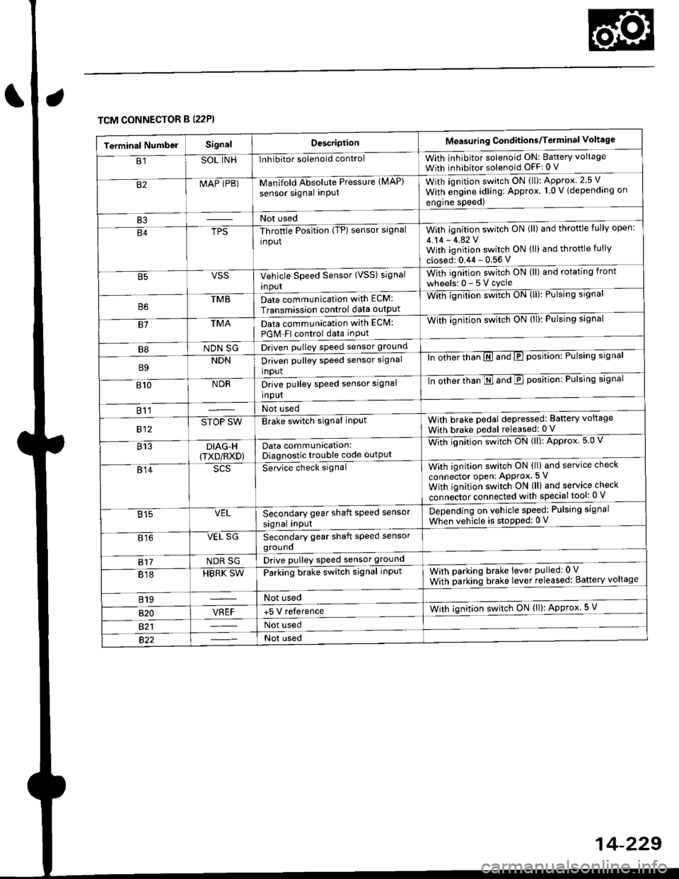
TCM CONNECTOR B (22P}
Terminal NumbelSignalDescriptionMeasuring Conditions/Terminal Voltage
B1SOL INHInhibitor solenoid controlWith inhibitor solenoid ON: Baftery voltage
With inhibitor solenoid OFF: 0 V
82MAP (PB)-M an if old Absol r-rte Pressure IMAP)
sensor signal inPUtWith iqnition switch ON (ll): Approx.2.5 V
With e;gine adling: Approx. 1.0 V (depending on
engine speed)
B3Not used
B4TPS-Throttle Position (TP) sensor signal
input
With ignition switch ON (ll) and throftle fully open:
4.14 - 4.42 VWith ignition switch ON (ll) and throttle fully
closed: 0.44 - 0.56 V
VSSVehicle Speed Sensor (VSS) signal
Inpur
With ignition switch ON (ll) and rotating front
wheelsr 0-5Vcycle
TMBData communication with ECM:
Transmission control data outpUt
With ignilion swltch UN lll): rulslng slgnar
81TMAData communication with EClvl:
PGM Fl control data inPut
With ignition swltch uN {ll,: l-ulslng slgnal
B8NDN SGDriven pulley speed sensor ground
B9NDNDriven pulley speed sensor signal
input
ln other thTnE and E position: Pulsing signal
810NDRDrive pulley speed sensor signal
Input
-tn ottrer ttran E ana E position: Pulsing signal
811Not used
812STOP SWBrake switch signal inPutWith brake pedal depressed: Battery voltage
With brake pedal released: 0 V
813DIAG-H(TXD/RXD)Data communication:Diagnostic trouble code outPut
Wittr ignitio.r s*itct' ON (ll): Approx 5.0 V
814Se-ice ctrect signatWith ignition switch ON (ll) and service check
connector oPen: APProx.5 V
With iqnition switch ON (ll) and service check
"onn"itot. connect"d with special tool: 0 V
Secondary gear shaft speed sensor
signal input
Depending on vehicle speed: Pulsing signal
When vehicle is stoPped: 0 V815VEL
816VEL SGSecondary gear shaft speed sensorgrouno
817NDR SGDrive pulley speed sensor ground
818HBRK SWParking brake switch signal inPutWith parking brake lever pulledr 0 V
With parking brake lever released: Battery voltage
819Not used
B�20VREF+5 V relerenceWith ignition switch ON (ll): Approx 5 V
821Not used
Not used
Page 936 of 2189
Troubleshooting Flowchart - Shift Control System
NOTE: Record all freeze data before you troubleshoot.
Po$ible Cause
Faulty 3hift control systemOgD ll Scan Tool indicates Code
P'1890.Self-diagnosi3 E indicator light
indicates Code 42.
Check for Anolhet Code:
Check whether the E indicator
light indicates another code.
Pertorm the TroubleshoolingFlowchrrt to. th€ indicet.d
Codelsl.
ls the E indicator light indi
cate another code?
Check Stall Speed RPM:Measure the stall speed RPM(see page 14-298).
ls the stall speed over 3,500 rpm?
ls the slall speed below 2.0o0 rpm)
Test-drive and Check E ngine
Speed:1. Drive the vehicle at 30 mPh(50 km/h) constantlY for sev_
eral manutes.2. Check the engine speed
ls the engine speed within the
specification (see page 14 296
and 14 297\?
14-259
Page 937 of 2189

Electrical Troubleshooting ('96 - 98 Models)
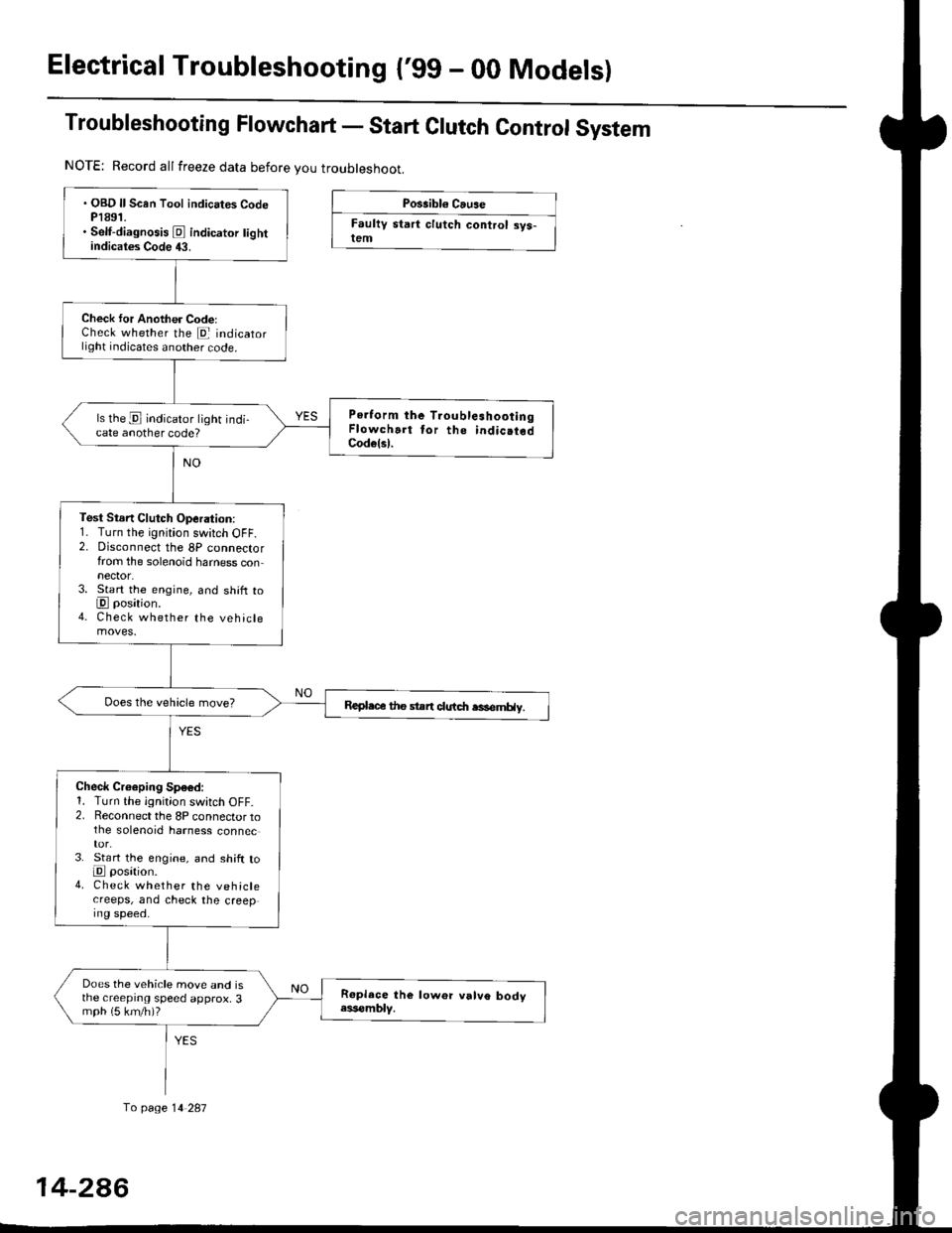
Troubleshooting Flowchart - Start Clutch Control System
NOTE: Record all freeze data before you troubleshoot.
Po$ible Ceuaa
Frulty start clutch cont.ol 3ys-tem
14-260
OBO ll Scan Tool indic.le3 Cod6P1891.Solt-diagnosis E indicator lightindicates Code (1.
Check for Another Codo:Check whether the @ indicatorlight indicates another code.
Poiform tho TroublcahootlngFlowchrrt lor the indicat.dCode(sl.
ls the E indicator light indi-cate another code?
Test Strrt Clutch Oper.tion:1. Turn the ignition switch OFF.2. Disconnect the 8P connectorfrom the solenoid harness con,nector.3. Start the engine, and shift toE position.4. Check whether the vehiclemoves.
Rcplaca th. strrt dudt r$amt ly.
Check Creeping Spe€d:1. Turn the ignition switch OFF.2. Reconnect the 8P connector tothe solenoid harness connec-tor,3. Start the engin6, and shift toE position.4. Check whether the vehiclecreeps, and chock the creep-Ing speed.
Does the vehicle move and isthe creeping speed approx.3mph (5 km/h)?
To page 14-261
E
Page 962 of 2189
Troubleshooting Flowchart - Shift Control System
NOTE: Record allfreeze data before you troubleshoot
Possible cause
Faultv shift control svstem' OBD ll Scan Tool indicates Codo
P1Ato.. Self-diagnosis E indicator light
indicatos Code 42.
Check for Anoth€r Code:Check whether the E indicator
light indicates another code.
P€rform the Tloubleshooting
Flowchart for the indicated
Code(sl.
ls the E indicator light indi
cate another code?
Check Stall Speed RPM:
Measure the stall sPeed RPM(see page 14-298).
ls the stall speed over 3,500 rpm?
ls the stall speed below 2,000 rpm?
Test-drive and Check Engine
Speed:L Drive the vehicle at 30 mph
150 km/h) constantly for sev-
eral mlnutes.2. Check the engine speed
ls the engine speed within the
specification (see Page 14'296
and 14'297)?
14-245
Page 963 of 2189

Electrical Troubleshootang ('gg - 00 Models)
Troubleshooting Flowchart - Start Clutch Control System
Possibl€ Cause
Faultv start clutch control sys-lem
NOTE: Record allfreeze data before you troubleshoot.
fo page 14 287
. OBD ll Scan Tool indicates CodeP1891.. Self-diagnosis E indicator tightindicates Code 43.
Check for Another CodelCheck whether the E indicatorlight indicates another code.
Perform the TroubleshootingFlowchart tor the indic.tedCodelsl.
ls the E indicator light indi-cate another code?
Test Stsn Clutch Operation:1. Turn the ignition switch OFF.2. Disconnect the 8P connectorfrom the solenoid harness connector.3. Start the engine, and shift toE position.4. Check whether the vehiclemoves.
Repl.c€ the stan clutdt rasemHy.
Check Croeping Sp€6d:1. Turn the ignition switch OFF.2. Reconnect the 8P connector tothe solenoid harness connec
3. St€rt the engine, and shift toE posation.4. Check whether the vehiclecreeps, and check the creeping speed.
Does the vehicle move and isthe creeprng speed approx, 3mph (5 km/h)?
14-2A6
Page 970 of 2189

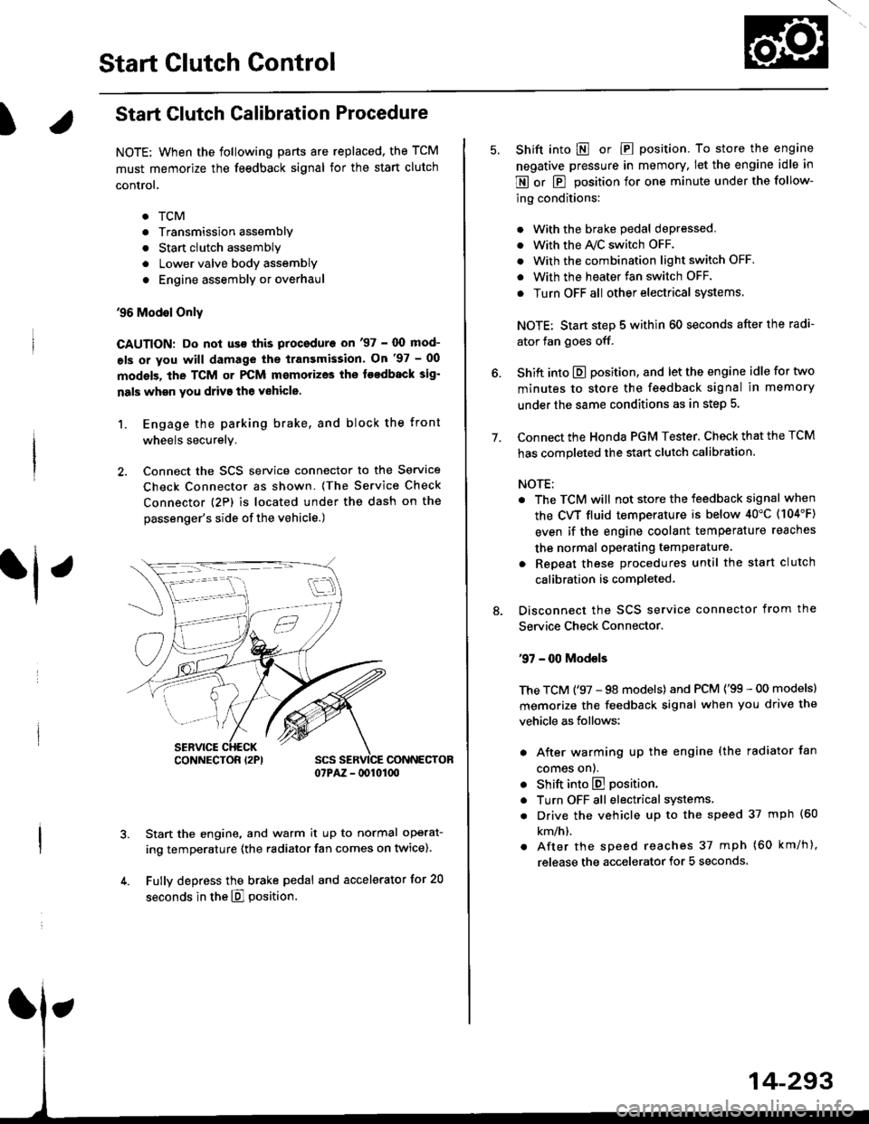
Start Clutch Control@
T
Start Clutch Calibration Procedure
NOTE: When the following parts are replaced, the TCM
must memorize the feedback signal for the start clutch
control.
. TCM
. Transmissionassembly
. Stan clutch assembly
. Lower valve bodv assembly
. Engine assembly or overhaul
'96 Model Only
CAUTION: Do not uso this procsdure on'97 - (X) mod-
els or you will damage the transmission. On '97 - 00
models, the TCM or PCM memorizes ths loodback sig'
nals when you drive the vehicle.
1. Engage the parking brake, and block the front
wheels securely.
2. Connect the SCS service connector to the Service
Check Connector as shown. (The Service Check
connector (2P) is located under the dash on the
passenger's side of the vehicle.)
CONNECTOR07PAZ - lDl01(xt
Start the engine, and warm it up to normal operat-
ing temperature (the radiator fan comes on twice).
Fully depress the brake pedal and accelerator for 20
seconds in the E] position.
rl ,
CONNECTOR I2PI
14-293
7.
Shift into E o|. E position. To store the engine
negative pressure in memory. Iet the engine idle in
E or E position for one minute under the follow-
ing conditions:
. With the brake pedal depressed,
. with the y'\/c switch oFF.
. With the combination light switch OFF.
. With the heater fan switch OFF.
. Turn OFF all other electrical systems
NOTE: Start step 5 within 60 seconds after the radi-
ator fan goes off.
Shift into E position, and let the engine idle for two
minutes to store the feedback signal in memory
under the same conditions as in step 5.
Connect the Honda PGM Tester. Check that the TCM
has completed the start clutch calibration.
NOTE:
. The TCM will not store the feedback signal when
the CVT fluid temperature is below 40"C (104'F)
even if the engine coolant temperature reaches
the normal operating temperature.
. Repeat these procedures until the start clutch
calibration is completed-
Disconnect the SCS service connector from the
Service Check Connector.
'97 - 00 Models
The TCM ('97 - 98 models) and PCM ('99 - 00 models)
memorize the feedback signal when you drive the
vehicle as follows:
. After warming up the engine (the radiator fan
comes onl.
. Shift into E position.
. Turn OFF all electrical systems,
. Drive the vehicle up to the speed 37 mph (60
km/h).
. After the speed reaches 37 mph (60 km/h),
release the accelerator for 5 seconds.
Page 978 of 2189

1.
Start the engine.
Shift to the respective shift lever positions in the table, and measure the following pressures at 1'500 rpm'
. Forward Clutch Pressure
. Reverse Brake Pressure
. Drive Pulley Pressure
. Driven Pulley Pressure
8. Shift to E posltion, and measure the lubrication pressure at 3,000 rpm'
Disconnect the special tool after pressure testlng
Install the sealing boits in the jnspection holes with new sealing washers, and tighten the bolts to the specified
toroue.
TOROUE: 18 N.m {1.8 kgf'm, 13 lbf'ft}
CAUTION: Keep all foreign particles out of the transmission'
9.
10.
PBESSURESHIFT LEVER
POSmONSYMP{OMPROBABLE CAUSE
FLUID PRESSURE
Standard/Ssrvice Limit
Forwa rd
Clutch
ENo or low for-
ward clutch
pressure
Forward Clutch1.4 - 1.75 MPa
(14.3 - 17.8 kgtcm'�, 203 - 253 Psi)
Reverse
Brake
tsNo or low
reverse brake
pressure
Reverse Brake1.4 - 1.75 MPa
(14.3 - '17.8 kg7cm'�, 203 - 253 Psi)
Drive
Pulley
NNo or low
drive pulley
pressure
ATF pump, PH reg-
ulator valve, PL
regulator valve,
Shift valve
0.2 - 0.7 MPa
(2 - 7.1 kgflcm'�, 28 - 101 Psi)
Drive pulley
pressure roo
high
PH regulator valve,
PL regulator valve,
Shift valve. Shift
control linear
solenoid
Driven
Pulley
No or low
driven pulley
pressure
ATF pump, PH reg-
ulator valve, Shift
valve, Shift control
linear solenoid
1.5 - 2.3 MPa
(15.3 - 23.5 kg?cm'�, 218 - 334 Psi)
Driven pulley
pressure too
h igh
PH regulator valve
LubricationNo or low
lubrication
pressure
ATF pump,
Lubrication valve
Above 0.2 MPa
(Above 2 kgf/cm'�. 30 Psi)
14-301
Page 981 of 2189

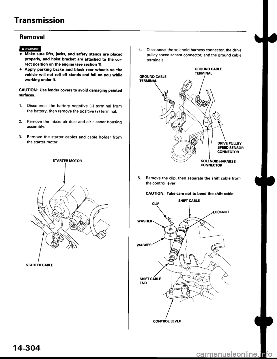
Transmission
Removal
@. Mako suro lifts. iacks, and satety stands are placod
properly, and hoi3t bracket are attached to lhe cor-
rect position on the engine {see soction 1}.
. Apply parking brake and block r€ar wheels so tha
vehicle will not roll off stands and fall on you while
working undor it.
CAUTION: Use tender covers to avoid damaging painted
surfaces.
Disconnect the battery negative (-) terminal from
the battery, then remove the positive (+)terminal.
Remove the intake air duct and air cleaner housing
1.
assembly.
3. Remove the starter cables and cable holder from
the starter motor.
STARTER CABLE
STARTER MOTOR
14-304
4, Disconnect the solenoid harness connector, the drivepulley speed sensor connector, and the ground cable
terminals.
DRIVE PULI.-EYSPEED SENSORCONNECTOR
SOLENOIO HARNESSCONNECTOR
Remove the clip, then separate the shift cable from
the control lever,
CAUTION: Take care not to bend the shift cable.
WASHER
WASHER
GROUND CABLE
GROUND CAELE
CONTROL LEVER
S}IIFT CABLE