Page 1846 of 2189
Power Distribution
- From Fuses to Relays and Components (contd)
FUSE 15AIITIFIIATORsP iE soa754
J-l
c4t912 I C421PHO|O 63virtu is-- : : I lj;:o,19^63
l,lll,nl
tl
i ! [8ig*'"*: : LOAD, I DETECTOR, I GLD} UI{17' | (ELDI u
: i Page 22
I
I
\
VEW 5A
{)
I
L-------J
TRANSMISSIONCONTROLMODULE [rCM]Page 39-4
vtEw 69
815
tl
tl
GAUGEASSEMBLYPage 22-1
, a PHO|O S
, UNDER-HOOD' FUSE/RELAY BOXI PHO|O 7
- '96-'�98 CVT
10-4
Page 1853 of 2189
* = '96-98 models except D1685,'99100 D16Y5 with lVl/T
UNDER-HOODFUSE/RELAYBOX
'98CW - -.
, r--1
:ll:,tt:
: r--J ;, TRANSMISSION ,. CONTROL' MODULE OCM) :' Page 3g-4 ;I PHOIO 121I vlEW 69
I
I
\FUS€ 47aAcx uP
c351
WHT/BLIJ
WHT/BLU
WHT/BLU
18c4'l t
vlEw 60
WHT/ALU
WHT/ALU
11c440
WHT/BLU
10
' WHT/BLU
, 423
c131
vtEw 59
WHT/BITJ
'96-'98
models
I
tl
tl
STEREORADIOTUNERPage 150
'99-'m
modelsmodeB
'99-'�00
models
c723c723
vtEw 57
wHr/atu
810B�21cc10)
tl
ll
HEATERCONTROLPANELPages 60-1,61-2,62-2,and 63-2
vtEw 76
tl
tl
POWERTRAIN oTENGINE CONTROLMODULE(PCM or ECM)
Page 23, 24, ot 25
AUDIOUNITPage 150
tl
HEATERCONTROLPANELPages 62-1and 63'1
10-1 1
Page 1858 of 2189
----" A/T -----t
DRIVEN PULLEY , ^.,.
;iftTBilis'".f l5Ftr,.""_
co'rinienixnn '. Pase 23'2
SPEED SENSOR ; .'-\.SHIELD 'F--.1
TDC/CKP/CYPSENSORSHIELDPage 20
ll
r_:.-i
23-13
t1
23- l4
tl
PRIMARY SECONDARYHO2S HO2SSHIELD SHIELDPages 23-8, Pages 23-9,23-10. and 23-11. and
--- CW ----.
TRANSMISSION ;CONTROLMODULE(TCM) ,Page 39-5 :PHO|O 121vlEw 69r____1 ,
tt:
tt:L----J,
. D16Y8engine
SECONDARY .
HO2S :SHIELD ;Page 23-11
l. - -..1 ;
tt:(D16Y/i D15Y8)Page 39-1
l.--.1
1l
r:--iBFN/BLKARN/BLK
A4
6FN/BLK' EFN/BI
i i srco"oo"t :' I GEAR SHAFT
I I Or MAtN!'tAt I. II SPEED SENSOR '
CW. - D16Y8 -, engine: N SENSoR SHTELD ,
i !i?il3li*u,, i
CWSHIELD :Page39-4,
CRANK-SHAFTSPEEDFLUCTU-ATION(cKF)SENSORPage 23-2
tl
ll
;I;..
26
i xNocx' SENSOR, (KS)' SHIELD
, Fage zJ-5
: F--.1
:ll
iilr-:i
----:.--------:
c442(Terminals 18-20)
c10.1 PHofo 125\HOTO 21 VIEW 54vtEw 29
'----- cw ----'
DRIVE
BFN/BLK
PULLEY :SPEEDSENSORSHIELDPage 39-4 :
1.---{ :I t;
cl30Oermlnal8'l-10)
vtEw 52
14-'�,
Page 1876 of 2189
- Automatic Transmission (D1685)
c352
vtEw27
FUSE 42tGtao
.I ELECTRICALI LOADr DETECIOn
| (ELD) uNtrI PHOTO 9
I
UNDER.HOOOFUSE/RELAYBOX
r=-----L-_-_-_-_-_-=_-_-Tl.*1"","1#"Ei]""
li F 3,"j,[',ul
WHT/BLK
. J 9,1'3.WHt a V|EW 14
tcx,^ ) Page 10'
PHOTO 76
1--*---''!N"t- \o3bz7
See PowerDistribution,page 10.
c433
ALKRED4
r-^==.1
Stadorcontrol
POWERTRAINCONTROLMODULE (PCM)
c101
vtEw 28
ll
"'{----1iLi.' | |
Li-gl{l======i---i
"i*-iIr-m'
:il
See PowerDistribdion,Page '10.
".u,"if---'
-,*! s#;:{"
BLKAVHT N V/EW a t
STARTERCUTFELAYPHO|O 129
(99100)
A"/T GEARPOStTtONswrTcH
See PGlr-Fl,page 25.
STARTER
c419
FUSE 31STAffER Src{AI7.54
UNDER-DASHFUSE/NELAYBOX
BLKREO
11
"'-";;tr
A't 3
BATTERY
21-1
Page 1886 of 2189
PGM-FI (All '9G'98 Models except Dl685; '99r0O D16y5 with M/T)
TRANSMISSIONCONTROLMODULE (TCM)
llEv/ 69
ECM ECMcontrol controlReference data datavollage inDutNREF) OMA}:q{.J
(VREF) OMA) OMB)Reference ECM ECMcontroldatajnput
EGRcontrol shift' I solenoid
i
-l
"""'"x :i1",'
sofenoid lock Pa(klvave Circult neutr; I vave circuit neutral| | control control inPut, ! (EsOLr {sru, (A}FNP):L------
voltag€ controldataoutput
I
{
ta
i;;;;';;
."
*
'i\,
' circuit neutral Reverse D4 D3 2 indtcator, ;' control input input input input input control | -,| (sLU) rAlPNPr TATPFI {ATpO4i dlPD3) tAfPzr rDa rNDl | /
[J=:ITTIT'{t
' Interlock See Automatrc: Svstem Transmission Controls I
i i controt
i
"'J;:;;,.,"^,
!
l1l
"lL
:1,.
i
".f:;;,.,"^, 1.,."n,
: I lt ti.."stEBkTJBi ""il*l"*
: | /" I SOLENOTD VALVE
i \J PHaro 12a I
i
t'i!",,,
Bi"ifit**1
';
i l ;;;a ',, pase 14 !'#$tl ii{"Ff*,
i
*-1.
---f !.gg1mr..
' 4 cror| - PHAfO 123
23-6
Page 1983 of 2189

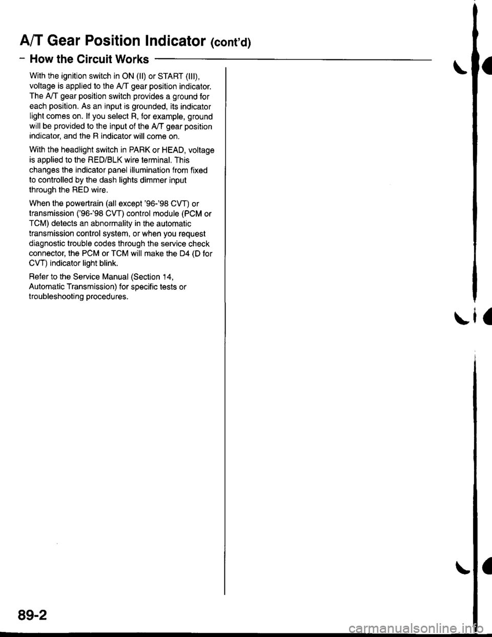
A/T Gear Position Indicator (conrd)
- How the Circuit Works
With the ignition switch in ON (ll) or START (lll),
voltage is applied to the A,/T gear position indicator.
The A,/T gear position switch provides a ground for
each position. As an input is grounded, its indicator
light comes on. lf you select R, for example, ground
will be provided to the input of the A,/T gear position
indicato( and the R indicator will come on.
With the headlight switch in PARK or HEAD, voltage
is applied to the RED/BLK wire terminal. This
changes the indicator panel illumination from fixed
to controlled by the dash lights dimmer input
through the RED wire.
When the powertrain (all except '96-'98 CVT) or
transmission ('96198 CVT) control module (PCM or
TCM) detects an abnormality in the automatic
transmission control system, or when you request
diagnostic trouble codes through the service check
connector, the PCM or TCM will make the D4 (D for
CVT) indicator light blink.
Refer to the Service Manual (Section 14,
Automatic Transmission) for specific tests or
troubleshooting procedures.
\ia
89-2
Page 2101 of 2189
Gomponent Location
121. Behind Left Kick Panel ('96-'98 CVT)\124. Rear of Engine Compartment (CVT)
TRANSMISSIONCONTROL MODULE(rcM)
122. Right Side Lower Engine Compartment (CVT)125. Behind Right Side of Dash Panel
\
123. Right Front of Engine (CVT)126. Underside of Hatch Lid
k
2A1-20
\
Page 2108 of 2189

-
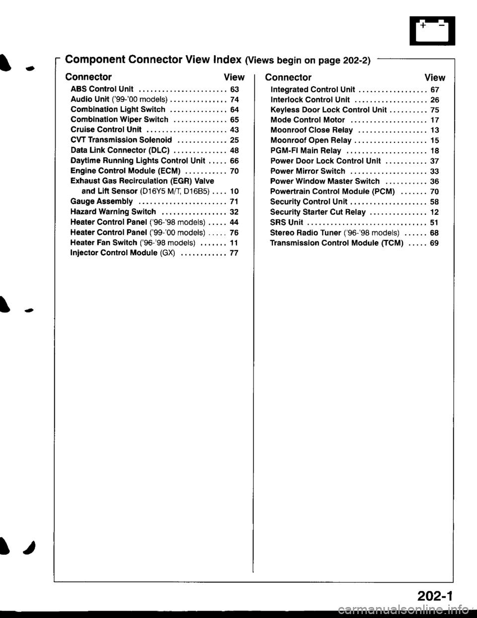
Component Connector View Index (Views begin on page 202-21
Connector View
ABS Control Unit........ ......63
Audio Unit ('99-'00 models) ......74
Combination Light Switch . . . . . . . . . . . . . . . 64
Combination Wiper Switch . . . . . . . . . . . . . . 65
Cruise Control Unit.... .....43
C\TTTransmission Solenoid ............. 25
Data Link Connector (DLC) ..... 48
Daytime Runnlng Lights Control Unit ..... 66
Engine control Module (ECM) ...........70
Exhaust Gas Recirculation (EGR) Valve
and Lift Sensor (D16Y5 Mfl, D1685) . . . . 10
Gauge Assembly .............71
HazardWarnlngSwitch,,. .,,,...,,,,... 32
Heater Control Panel ('96-'98 models) .....44
Heater Control Panel ('99-'00 models) ...., 76
Heater Fan Switch ('96-'98 models) ,,,.... 11
fniector Control Module (GX) ............77
I/
202-1
Connector View
Integrated Control Unit .......,. 67
f nterfock Control Unit .... ...... 26
Keyfess Door Lock Control Unit . . . . , . . . . . 75
Mode Control Motor ... ........'17
Moonroof Close Relay .. .......13
Moonroof Open Relay ... .......15
PGM-FI Main Relay .. .......... 18
Power Door Lock Conlrol Unil ..... ...... 37
Power Mirror Switch .,... ...... 33
Power Window Master Switch .,.........36
Powertrain Control Module (PCM) .......70
Security Control Unit ..., ..,,... 58
Security Starter Cut Belay ... ...,,,....,, 12
SRS Unit ............. 51
Stereo Radio Tuner ('96-'98 models) ...... 68
Transmission Control Module CICM) .....69