Page 1024 of 2189
Transmission
Installation
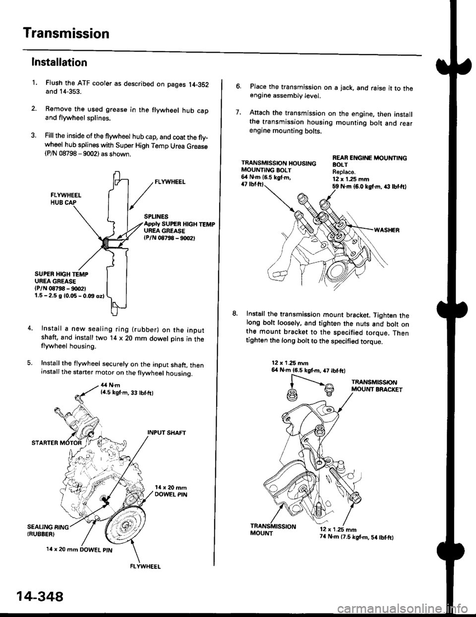
Flush the ATF cooler as described on pages 14-352and 14-353.
Remove the used grease in the flywheel hub caDand flywheel splines.
Fill the inside of the flywheel hub cap, and coat the fly-wheel hub splines with Super High Temp Urea Grease(P/N 08798 - 9002) as shown.
L
SEALING RING{RUEBER)
SPLINESApply SUPEB HlcH TEMPUREA GREASElPlN 08798 - 90O2t
SUPER HIGH TEMPUREA GREASE(P/N 08798 - !)00211.5-2.5 g 10.05-0.t9 oz)
Install a new sealing ring (rubber) on the inoutshaft, and install two '14 x 20 mm dowel Dins in theflywheel housing.
Install the flywheel securely on the input shaft, theninstallthe starter motor on the flywheel housing.
4,1Nmla.5 kgt.m, 33 tbt.ft)
INPUT SHAFT
STARTER
l4 x 20 mm DOWEL ptN
.4;i "lrj
,i rr,"r., ., a
14-348
FLYWHEEL
MOUI{T74 N.m (7.5 tstm,5a tbtftt
6. Place the transmission on s jack, and raise it to theengine assembly level.
7. Anach the transmission on the engine, then installthe transmission housing mounting bolt and rearengine mounting bolts.
TRANSMISSION HOUSINGMOUNTING BOIT6,1 N.m 16.5 kgl.m,47 tbtttl59 Nrn {6.0 kgl.m. ,€ lbt ftl
WASHER
lnstall the transmission mount bracket. Tighten thelong bolt loosely, and tighten the nuts and bott onthe mount bracket to the specified torque. Thentighten the long bolt to the specified torque.
REAR ENGINE MOUNTINGBOLTReplace.12 x 1.25 mm
12x 1.25 mn6,r N'm 16.5 kgtm,47 tbtftl
l-".--..-,^
G\V
TRANSMISSONMOUNT BRACKET
12 x 1.25 mn
Page 1027 of 2189

22. Install the shift cable end on the control lever, and
install the shift cable on the shift cable bracket'
CAUTION: Take care not to bend the shift cable'
23. lnstall the clip in the direction shown.
LOCKNUT
SHIFI CABLE 29 N m {3.0 kg{ m, 22lblftl
SHIFT CABLEERACKET
WASHERIPLASTIC)
CONTROL LEVER
24, Connect the solenoid harness connector. the drive
pulley speed sensor connector. and the ground
cable terminals.
6x1.0mm12 N.m {1.2 kgf.m.8,7 rbtft)
GROUND CABLETERMINAL 6x1.0mm
GROUNDTERMINAL
12 N.m {1.2 kgf'm,8.7lbtfrl
DRIVE PULLEYSPEED SENSORCONNECTOR
SOLENOID HARNESS
CONNECTOR
25. Connect the starter motor cable on the starter motor.
and install the cable holder.
NOTE: When installing the staner motor cable. make
sure that the crimped side of the ring terminal is
facing out (see section 23).
STARTEB
BMOUNTING NUT
9 N.m (0.9 kgf m,7 lbf ft)
26. Install all removed connectors and clamps'
27. Install the distributor.
28. Install the intake air duct and air cleaner housing
29.
assemDly.
Refill the transmission with the recommended
Genuine Honda CVT Fluid (see page 14-2991
CAUTION: While filling the CvT Fluid, bs surs not io
allow dust and other fotoign particles to entor into
the transmission.
Connect the battery positive (+) terminal first, then
the negative (-l terminal to the battery'
Check the ignition timing (see section 23).
Start the engine. Set the parking brake, and shift the
transmission through all gears three times Check
shift cable adjustment (see page 14-355).
Check the front wheel alignment (see section 18)
Let the engine reach operating temperature (the
radiator fan comes on) with the transmission in lXl
or E position, then turn it off and check fluid level'
Perform the start clutch calibration procedure on
page 14-293.
Road test as described on pages 14-296 and 14-297
30.
31.
34.
36.
STARTER MOTOR
14-351
Page 1484 of 2189
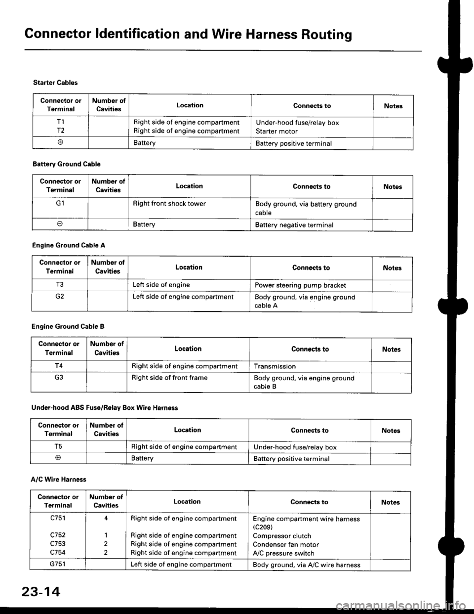
Connector ldentification and Wire Harness Routing
Connector or
Terminal
Number of
CavitiesLocalionConnec{s toNotes
T,I
r2
Right side of engine compartment
Right side of engine compartment
Under-hood fuse/relay box
Starter motor
BatteryBattery positive terminal
Starter Cables
A/C Wire Harness
Battery Ground Cable
Connector or
Terminal
Number of
CavitiesLocationConn€cts toNotos
Right front shock towerBody ground, via battery ground
caDte
oBafteryBattery negative terminal
Engine Ground Cable A
Conn€qtor or
Terminal
Number ot
CavitiosLocationConnects toNoles
T3Left side of enginePower steering pump bracket
G2Left side of engine compartmentBody ground, via engine ground
cable A
Engine Ground Cable B
Connector or
Terminal
Number of
CavitiesLocationConnecls toNoles
T4Right side of engine compartmentTransmission
Right side of front frameBody ground, via engine ground
cable B
Under-hood ABS Fusa/Relay Box Wire Harness
Connector or
Tgrminal
Number oI
CavitiesLocationConneqts toNotes
T5Right side of engine compartmentUnder-hood fuse/relay box
@BaneryBattery positive terminal
Connector or
Terminal
Number of
CavitiesLocationConnects toNotes
c753
c754
1
2
Right side of engine compartment
Right side of engine compartment
Right side of engine compartment
Right side of engine compartment
Engine compartment wire harness(c209)
Compressor clutch
Condenser fan motor
A,/C pressure switch
Left side of engine compartmentBody ground, via A,/C wire harness
23-14
Page 1556 of 2189
Power Relays
Relay Test
Turn Signal/Hazard Relay:
See page 23-172
Normally-open type:
1. Check for continuity between the terminals.. There should be continujty between the No. 1 andNo.3 terminals when power and ground are con-nected to the No. 2 and No. 4 terminals.. There should be no continuity between the No. 1and No. 3 terminals when power is disconnected.
3
. Blower motor relay
. ABS pump motor relay
Terminal
-i*rt"r-*or\13
Disconnected
Connectedo
,I IIY F>rr €,?I
23-86
. Rear window defogger relay
Starter cut relayt '96 - 97 models
Horn relayi '96 97 models
Blower motor high relay: '99 - 0O mooersa
Page 1571 of 2189
-Performance Test
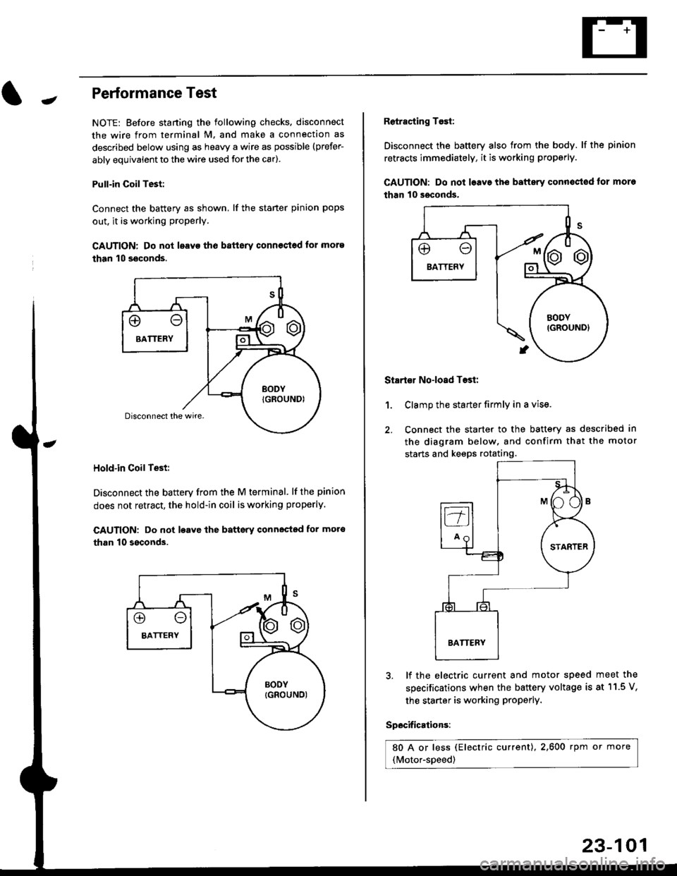
NOTE: Before staning the following checks. disconnect
the wire from terminal M. and make a connection as
described below using as heavy a wire as possible (prefer-
ably equivalent to the wire used for the car).
Pull-in CoilTest:
Connect the battery as shown, lf the staner pinion pops
out. it is working proPerly.
CAUTION: Do not leavo tho batterv connost€d for more
than 10 seconds.
Hold-in Coil Test:
Disconnect the battery from the M terminal' lf the pinion
does not retract, the hold-in coil is working properly.
CAUTION: Do not loavc lhe battsry connected for mot6
than 10 ssconds.
Retracting Tosi:
Disconnect the battery also from the body. lf the pinion
retracts immediately, it is working properly.
GAUTION: Do not loave the baftery conn€ctod tor more
than 10 seconds.
Startor No-load Tost:
Clamp the starter firmly in a vise.
Connect the starter to the battery as described in
the diagram below, and confirm that the motor
starts and keeps rotating.
1.
3, lf the electric current and motor speed
specifications when the battery voltage is
the starter is working ProPerly.
Specifications:
80 A or less (Electric current),2,600 rpm or more
(Motor-speed)
meet the
at 11.5 V,
23-101
Page 2069 of 2189
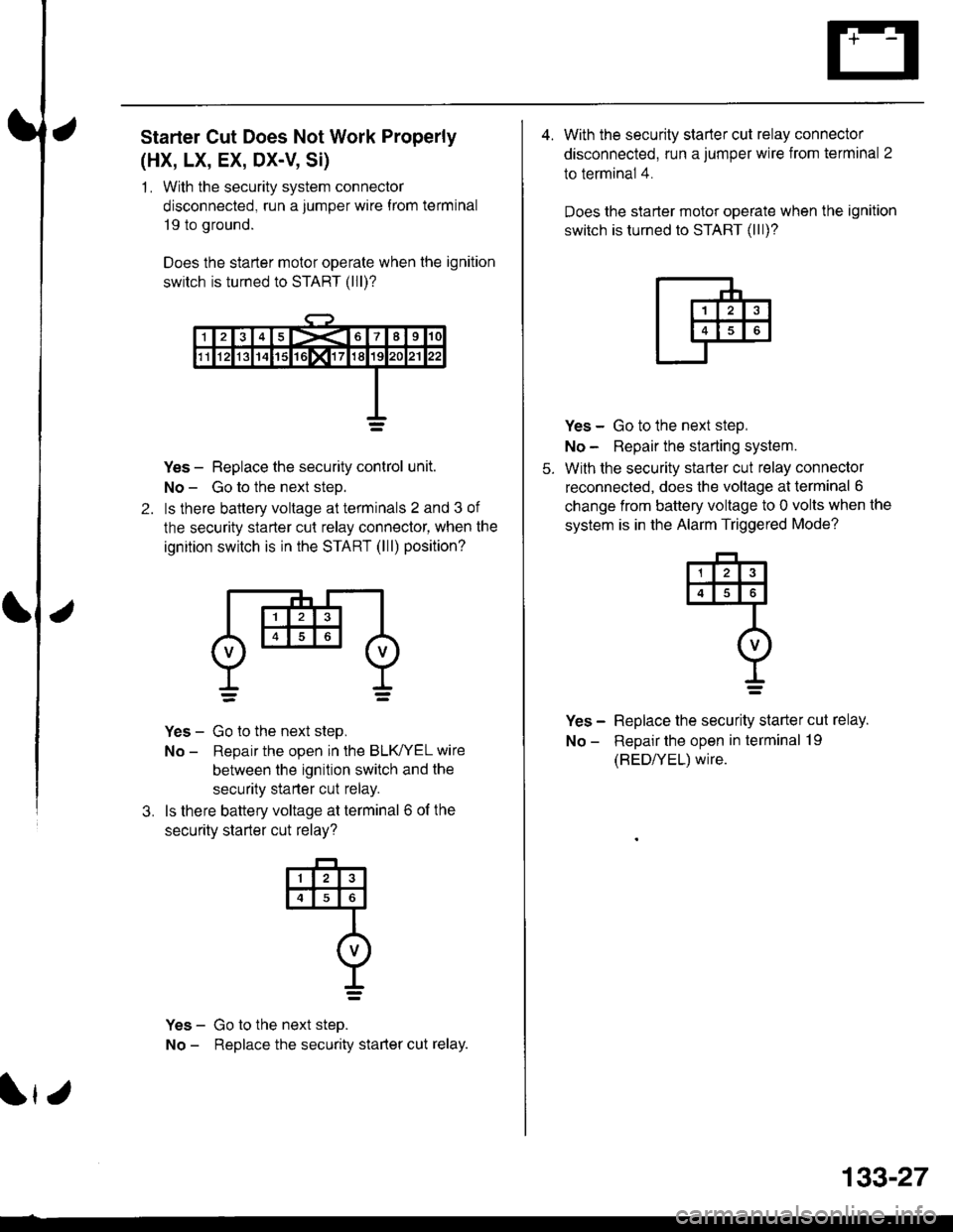
Starter Cut Does Not Work Properly
(HX, LX, EX, DX-V, Si)
1 . With the security system connector
disconnected, run a jumper wire f rom terminal
19 to ground.
Does the starter motor operate when the ignition
switch is turned to START (lll)?
2.
Yes - Replace the security control unit.
No - Go to the next steD.
ls there baltery voltage at terminals 2 and 3 of
the security starter cut relay connector, when the
ignition switch is in the START (lll) position?
Yes - Go to the next step,
No - Reoair the ooen in the BLK/YEL wire
between the ignition switch and the
security starter cut relay.
ls there battery voltage at terminal 6 of the
securitv starter cut relav?
Yes - Go to the next steo.
No - Replace the security starter cut relay.
3.
@
I=
r
133-27
4. With the security starter cut relay connector
disconnected, run a jumper wire from terminal 2
to terminal 4.
Does the slarter motor operate when the ignition
switch is turned to START (lll)?
5.
Yes - Go to the next step,
No - Repair the starting system.
With the security starter cut relay connector
reconnected, does the voltage at terminal 6
change from battery voltage to 0 volts when the
system is in the Alarm Triggered Mode?
Yes - Replace the security starter cut relay.
No - Repair the open in terminal 19
(BED/YEL) wire.
4
I=
Page 2070 of 2189
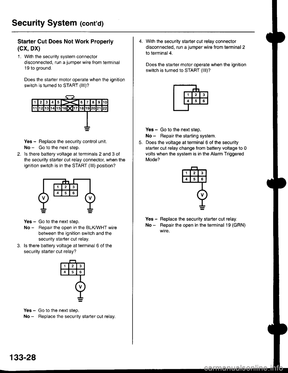
Security System (cont'd)
Starter Cut Does Not Work Properly
(cx, Dx)
1 . With the security system connector
disconnected, run a jumper wire f rom terminal
19 to ground,
Does the starter motor operate when the ignition
switch is turned to START (lll)?
Yes - Replace the security control unit.
No - Go to the next steo.
ls there battery voltage at terminals 2 and 3 of
the security starter cut relay connector, when the
ignition switch is in the START (lll) position?
Yes - Go to the next step.
No - Repair the open in the BLKMHT wire
between the ignition switch and the
security starter cut relay.
ls there battery voltage at terminal 6 of the
securitv starter cut relav?
Yes - Go to the next step.
No - Beplace the security starter cut relay.
4
o
t_=
133-28
4. With the security starter cut relay connector
disconnected, run a jumper wire from terminal 2
to terminal 4.
Does the starter motor operate when the ignition
switch is turned to START (lll)?
Yes - Go to the next steo.
No - Repair lhe starting system.
Does the voltage at terminal 6 of the security
starter cut relay change trom battery voltage to 0
volts when the system is in the Alarm Triggered
Mode?
Yes - Replace the security starter cut relay.
No - Repair the open in the terminal 19 (GRN)
wtre.
q
I=
Page 2108 of 2189
-
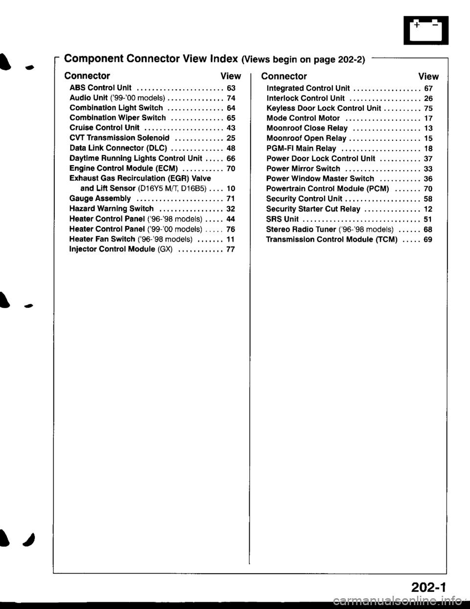
Component Connector View Index (Views begin on page 202-21
Connector View
ABS Control Unit........ ......63
Audio Unit ('99-'00 models) ......74
Combination Light Switch . . . . . . . . . . . . . . . 64
Combination Wiper Switch . . . . . . . . . . . . . . 65
Cruise Control Unit.... .....43
C\TTTransmission Solenoid ............. 25
Data Link Connector (DLC) ..... 48
Daytime Runnlng Lights Control Unit ..... 66
Engine control Module (ECM) ...........70
Exhaust Gas Recirculation (EGR) Valve
and Lift Sensor (D16Y5 Mfl, D1685) . . . . 10
Gauge Assembly .............71
HazardWarnlngSwitch,,. .,,,...,,,,... 32
Heater Control Panel ('96-'98 models) .....44
Heater Control Panel ('99-'00 models) ...., 76
Heater Fan Switch ('96-'98 models) ,,,.... 11
fniector Control Module (GX) ............77
I/
202-1
Connector View
Integrated Control Unit .......,. 67
f nterfock Control Unit .... ...... 26
Keyfess Door Lock Control Unit . . . . , . . . . . 75
Mode Control Motor ... ........'17
Moonroof Close Relay .. .......13
Moonroof Open Relay ... .......15
PGM-FI Main Relay .. .......... 18
Power Door Lock Conlrol Unil ..... ...... 37
Power Mirror Switch .,... ...... 33
Power Window Master Switch .,.........36
Powertrain Control Module (PCM) .......70
Security Control Unit ..., ..,,... 58
Security Starter Cut Belay ... ...,,,....,, 12
SRS Unit ............. 51
Stereo Radio Tuner ('96-'98 models) ...... 68
Transmission Control Module CICM) .....69