Page 1123 of 2189

)
1?
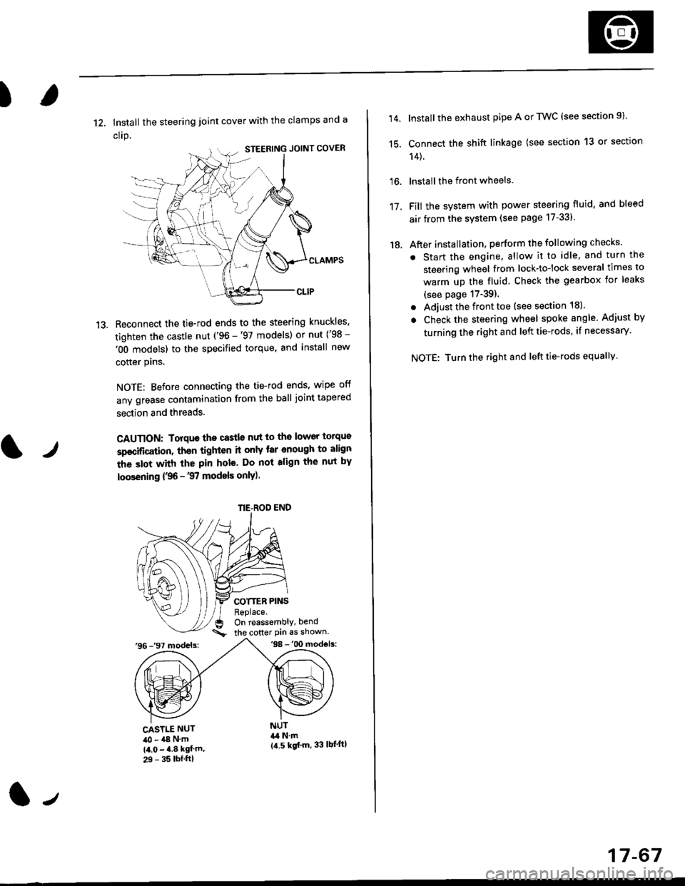
12, Install the steering joint cover with the clamps and a
clrp.
Reconnect the tie-rod ends to the steering knuckles,
tighten the castle nut ('96 -'97 models) or nut ('98 -
'OO models) to the specified torque, and install new
cotter plns.
NOTE: Before connecting the tie-rod ends, wipe off
any grease contamination from the ball joint tapered
section and threads.
CAUTION: Torquo the castle nut to the lower torque
sp€cification, then tighten it only tar enough to align
the slot with the pin hole. Do not align the nut by
loosening {,96 -'97 models only).
COTTER PINSReplace.On reassembly, bend
the cotter Pin 6s shown.'96 -'97 models:'98 -'00 mod€ls:
tr
CASTLE NUT40 - a8 N'm(4.0 - 4.8 kgf'm,29 - 35 lbf.ftl
NUT&l N.m{a.5 kgf'm, 33 lbl'ftl
NE-ROD END
(l-,
17-67
14.
15.
16.
17.
18.
Install the exhaust pipe A or TWC (see section 9).
Connect the shift linkage (see section 13 or section
14).
lnstall the front wheels
Fill the system with power steering fluid, and bleed
air from the system (see page 17-331
After installation, perform the following checks
. Start the engine, allow it to idle, and turn the
steering wheel from lock-tolock several times to
warm up the fluid. Check the gearbox for leaks
(see page 17-39).
. Adjust the front toe (see section 18).
. Check the steering wheel spoke angle. Adjust by
turning the right and left tie-rods, if necessary.
NOTE: Turn the right and left tie-rods equallv
Page 1232 of 2189
Doors
Front Door lndex
,ID:
WEATHERSTRIP
POWER WINDOWswtTcH
ffitr6-
fud-@a,
Ef
Adjustment, page20-23
DOORPROTECTOR
OOOR POCKET
r^r f i'I I ) t\' \-!
20-2
J$--"**^
Page 1239 of 2189
\L
lJ\
\flREAR CHANNEL N\
\,\
\
\i\Ill
ld 1l
6P lll
REo" c"AN"..: | 1lcoLLAR J I
)€)\IJ
6/
\3-
REGULATORHANOLE
:& fr\
r lll'All criss lLl
l'A sroeeen lll
W-*d
t a)" u\
*)u*ro* \
Repracement, pase 20 ,tt
l5[1tfCHANNEL
OUTER HANDLEReplacement, Page 20-11
STRIKERAdjustment,page 20'23
I
I
%grc
POWER WINDOWMOTOR
LOCK RODPROTECTOR
LATCHPROTECTORReplacement,page 20-12
POWER OOORLOCK ACTUATOE
t
20-9
Page 1243 of 2189

t}
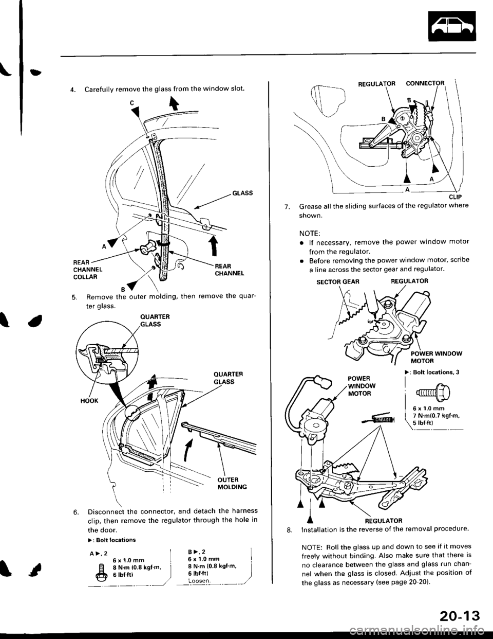
4. Carefully remove the glass from the window slot.
c\
REARCHANNELCOLLAR
Remove the outer molding, then
Ier grass.
remove the quar-5.
\
6. Disconnect the connector, and detach the harness
clip, then remove the regulator through the hole in
the door.
>: Bolt locataons
A>,2 ]6x1.0mm L
[l o t't.- to.a rsl -. j
fr e ttt ttt )---�.---.-,/
B >,26 x 'l.0 mmI N.m {0.8 ksl'm,6 tbf.ft)
I
)
OUARTER
20-13
7.
CLIP
Grease all the sliding surfaces of the regulator where
shown.
NOTE:
a lf necessary, remove the power window motor
from the regulator.
. Before removing the power window motor, scrloe
a line across the sector gear and regulator.
SECTOR GEARREGULATOR
POWER WINDOWMOTOR
>: Bolt locations,3POWERwTNDOWMOTOR
l'
-... er
A nicuuron
8. lnstallation is the reverse of the removal procedure.
NOTE: Rollthe glass up and down to see if it moves
freely without binding. Also make sure that there is
no clearance between the glass and glass run chan-
nel when the glass is closed. Adjust the position of
the glass as necessary (see page 20-20).
Page 1246 of 2189
Doors
Door Panel Replacement
NOTE: Take care not to scratch the door panel andother pa rts.
'1. Remove:
. Inner handle trim (see page 20-14). Mirror mount cover panel (see page 20-24)
2. lf applicable, remove the regulator handle bypulling the clip out with a wire hook.
REGULATOR HANDLE
WIRE HOOK
Remove the armrest pocket, then disconnect thepower window switch connector.
ARMRESTPOCKET
4. Remove the speaker cover, then remove lhe screws.
3.
I
>: Screw locations, 3
| 6b:a,'
L"_
COVER
20-16
TRIM PADREMOVER(Commercially
available)Snap-on#A'177, orequivalent1mm{0.04 in.)
5. Release the clips that hold the door panel. Removethe door panel by pulling it upward. Disconnect thespeaker connector.
NOTE: Remove the door panel with as little bendingas possible to avoid creasing or breaking it.
.L12 fim(0.47 in.) T-
>: Clip locations,
l^
J[
=l$
ll,\*
atr-
,,)
REMoVER tl-)
11.77 in.l
O) CONNECTOR
6. lnstallation is the reverse of the removat oroceoure.
DOOR PANEL
Page 1250 of 2189

Doors
Glass/Regulator Replacement (cont'dl
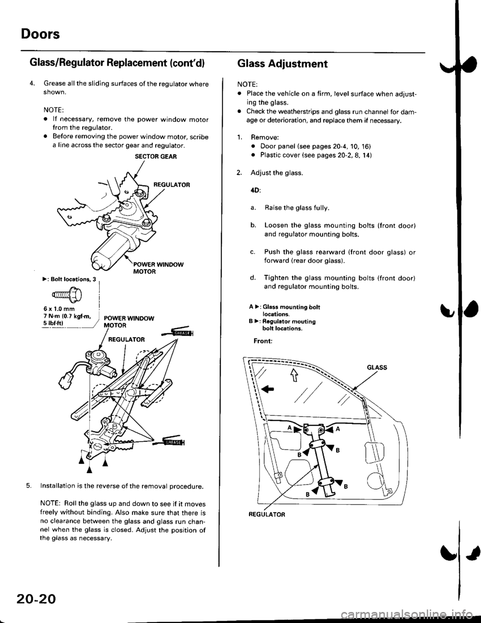
Grease all the sliding surfaces of the regulator where
shown.
NOTE:
. lf necessary, remove the power window motorfrom the regulator.
. Before removing the power window motor, scribe
a line across the sector gear and regulator.
REGULATOR
5. Installation is the reverse of the removal orocedure.
NOTE: Roll the glass up and down to see if it moves
freely without binding. Also make sure that there isno clearance between the glass and glass run chan-nel when the glass is closed. Adjust the position ofthe glass as necessary.
SECTOR GEAR
20-20
Glass Adjustment
NOTE:
. Place the vehicle on a firm, level surface when adjust-
ing the glass.
. Check the weatherstrips and glass run channel for dam-
age or deterioration, and replace them if necessary.
1. Remove:
. Door panel (see pages 20-4, 10, 16). Plastic cover (see pages 20-2,8, 14)
2. Adjust the glass.
4D:
Raise the glass fully.
Loosen the glass mounting bolts (front door)
and regulator mounting bolts.
Push the glass rearward (front door glass) or
iorward (rear door glass).
Tighten the glass mounting bolts (front door)
and regulator mounting bolts.
A >: Gl.3s mounting boltlocations.B >: Regulrtor moutingbolt loc.tions.
Front:
a.
b.
d.
REGULATOR
Page 1377 of 2189
'99 - 00 Models
SRS components are located in this area, Review the SRS component locations, precautions, and procedures in the SRS
section (24) betore perfoming repairs or service.
HEATER UNITReplacement, page 21'39
Overhaul, page 21-41
BLOWEB UNITReplacement, page 21-37Overhaul, page 21 38
HEATER FANswtTcH
RECIRCULATIONCONTROL MOTORTest, page 21-48Beplacement, page 21-48
AIR MIX CONTROL MOTOBTest, page 21-46Replacement, page 21 46
BLOWERTest, page 21-49
POWER TRANSISTORTest, page 21 50
HIGH RELAY
MODE CONTROLDIALHEATER VALVE CABLEAdjustment, page 21 45TEMPERATURE CONTROLDIALAdjustment, page 21-45
REAR WINDOWDEFOGGERswtrcHSee section 23MODEMOTORTest, page 21 47Replacement, page 2 l-47A/C SWTTCH
lwith A/cl
CONTROL SWITCH
21-3
Page 1391 of 2189

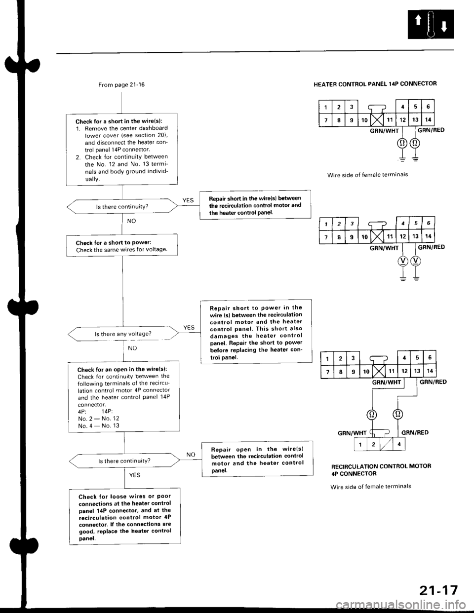
From page 21-16
ls there any voltage?
Check {or a short in the wire(s):1. Remove the center dashboardlower cover (see section 20),
and disconnect the heater con_
trol panel 14P connector'
2. Check for continuity between
the No. 12 and No. 13 termi-
nals and body ground individ-
Repair 5hort in the wire{sl between
the recirculation control motor and
the heater control Panel
Check Ior a short to Power:Check the same wires for voltage
Repair short to Power in the
wire {s) between the recirculationcontrol motor and the heater
control panel. This short also
damages the heater controlpanel. Repair the short to Powerbetore replacing the heater con-
trol panel.
Check lor an open in the wire(s):
Check for continuity between the
following terminals of the recircu
lation control motor 4P connector
and the heater control Panel 14P
4P. 14P:No.2 - No. 12No.4 No. 13
Repair open in the wirelsl
between the recirculation control
motor and the heater controlpanel.
ls there continuitY?
Check for loose wires or Poorconnections at the heater control
Danel 14P connector, and at the
recirculation control motor 4P
connector. lf the connections aregood, replace the heater control
Danel,
HEATER CONTROL PANEL 14P CONNECTOR
I;-?45
789'o lx11121314
GRN/WHT
0) (0
GRN/BED
Wire side of female terminals
GRN/RED
GRN/RED
RECIRCULATION CONTROL MOTOR
4P CONNECTOR
Wire side of female tetminals
I23i--?156
78I'olx11121314
GRN/WHT
V)(v
145
7IIrol\l rr1213
GRN/WHT
r zl/lt
21-17