1996 HONDA CIVIC ignition switch acc no power
[x] Cancel search: ignition switch acc no powerPage 1785 of 2189
)
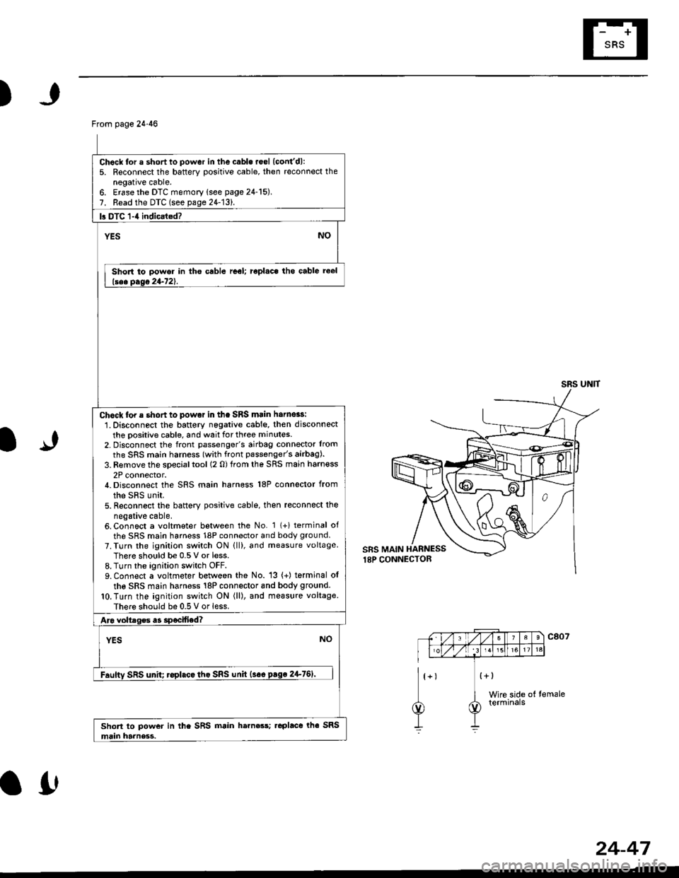
From page 24-46
Chock for a short to power in the cabls roel lcont'dl:5. Reconnect the battery positive cable, then reconnect thenegative cable.6. Erase the DTC memory lsee page 24-15).7. Read the DTC (see pa1e24-131.
b DTC 1-4 indicat€d?
YESNO
Short to power in tho cable reel; roplac. tho cable reel
lsee Dase 24-721.
Chock for e short to powot in the SRS main hornoas:
1. Disconnect the battery nogative cable, then disconnect
the positive cable, and wait for three minutes.2- Disconnect the front passenger's airbag connector lrom
the SRS main harness (with front passenger's airbag).
3. Remove the special tool (2 0) trom the SRS main harn€ss
2P connector./t. Disconnect the SRS main harness 18P connector from
the sRs unit.5. Reconn6ct the battery positive cable, then reconnect the
negative cable.6. Connect a voltmeter between the No. 1 {+i terminal of
the SRS main harness 18P connector and body ground.
7. Turn the ignilion switch ON lll), and measure voltageThere should be 0.5 V or less.8. Turn the ignition switch OFF.9. Connect a voltmeter between the No. 13 (+) torminal ol
the SRS main harness 18P connector 8nd body ground.
lO.Turn the ignition switch ON (ll), and measure voltage
There should be 0.5 V or less.
Aro voltrges a3 specified?
YESNO
Fauftv SRS unh; roplacc tho SRS unh {soe pago 2+761'
Short to power in the SRS main h.rness; .eplace rhe SRS
main harness.
SRS UNIT
IJ
a0
24-47
Page 1792 of 2189
Troubleshooting
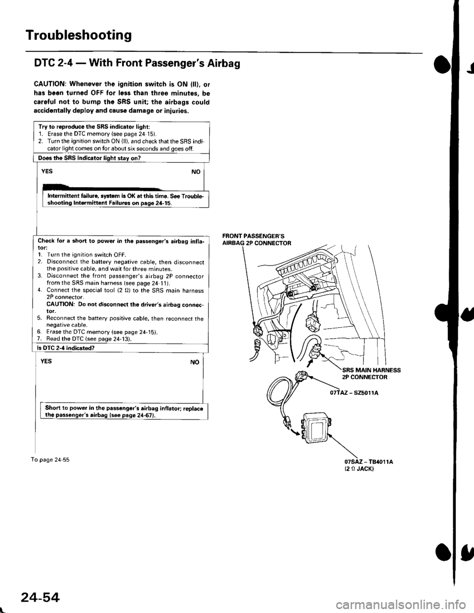
JDTC 2-4 - With Front Passenger's Airbag
CAUTION: Whenever the ignition switch is ON lll), or
has been turnod OFF for less than throa minutes, be
car.Iul not to bump the SRS unit; the airbags could
accidentally deploy and cause damage or iniuries.
Try to r€producethe SRS indicalor light:1. Erase the DTC memory (see page 24 15).2. Turn the ignition switch ON (ll), and check that the SRS indicator light comes on Ior about six seconds and goes off.
Does the SRS indicator light stay on?
YESNO
lDtermittenl failure, syltom b OK at this tima. S€e Trouble.shooting Int€rmittent Failuros on page 24-15.
Check lor a short to pow6r in the passenger's airbag intla-tor:1. Turn the ignition switch OFF.2. Disconnect the battery negative cable, then disconnectthe positive cable, and wait for three minutes.3. Disconnect the front passenger's airbag 2P connectorfrom the SRS main harness lsee page 2/t 11).4. Connect the special tool (2 O) to the SRS main harness2P connector.CAUTION: Do not disconnect the driver's airbag connec-tor.5, Reconnect the battery posit;ve cable, then reconnect thenegative cable.6. Erase the DTC memory (see page 24-15).7. Bead the DTC (see page 24-13).
ls OTC 2-4 indicatod?
YESNO
Short to power in the passenger's airbag inflator; replacetho passenger's airbag lsee page 24-67)
To page 24 55
AZ - SZ5011A
07sAz - TB4011A12 0 JACKI
L
MAIN HARNESS
24-54
Page 1798 of 2189
Troubleshooting
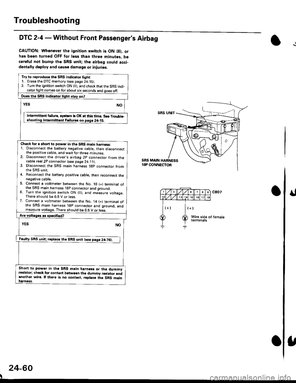
DTC 2-4 - Without Front Passenger's Airbag
CAUTION: Whenever the ignition switch is ON 0l). orhas been turned OFF for lsss lhan three minutes. becaretul not bump the SRS unit; the airbag could acci-dentally doploy and causo damage or iniuries.
Try to r€produc€ tho SRS indic.to. light:1. Erase the DTC memory (see page 24,15).2. Turn the ignition switch ON (ll), and check that the SRS indi-cator light comes on for about six seconds and go€s off.
Do€rthe SRS indicrtor light stay on?
NOrEs
lntormitteit t ilur., iyst m b OK at thb tim6. Sle Troubleshooling Intdmitt.nt Frilu.os on pag6 2+lS.
Check for a short to power in the SRS main h.rna3s:1. Disconnect the baftery negative cable, then disconnectthe positive cable, and wait for three minutes.2. Dlsconnect the driver's airbag 2p connector from thecable reel 2P connector (see page 24,11).3. Dlsconnect the SRS main harness l8p connector tromthe SRS unit.4. Beconnect the battory positiv€ cable, then reconnect thenegative cable.5. Connect a voltmeter between the No. lO (+) terminal ofthe SFS main hsrness 18P connector and qround.6. Turn the ignition switch ON {ll), and me-asure voltage.There should be 0.5 V or less.7. Connect a voltmeter between the No. 14 (+) terminal ofthe SRS main harness 18P connoctor and ground, andmeasure voltage. There should be 0.5 V or less.
A.e voltage. .3 spocifi.d?
YES NO
F.ulty SRS uniC .epla"" tl,. SnS unn l""" p"g" 2+7O:_l
Short to pow.r in tha SRS mlin harnc$ or tho dummyr*istor; chock lor contact bctwcen th. dummy r6ai3to. rndrnother wiro. lf there is no contrct, rcphcc the SRS msinhame3s.
SBS UNIT
SRS MAIN18P CONNECTOR
24-60
I
Page 1800 of 2189
Troubleshooting
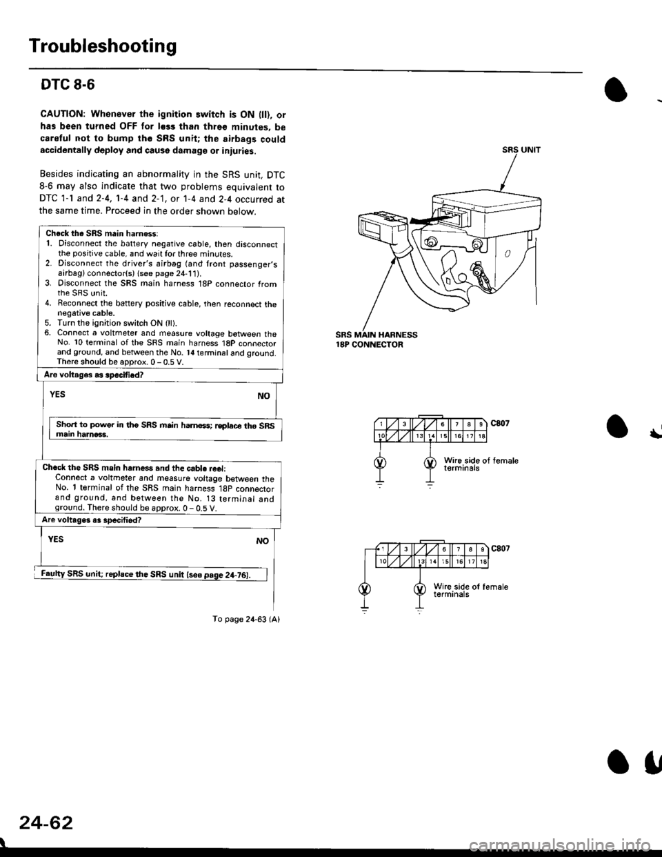
DTC 8-6
CAUTION: Whonover the ignition switch is ON lll), or
has been turned OFF for less than thro€ minutes, be
careful not to bump th6 SRS unit; the airbags couldaccidentally deploy and cause damage or iniuries.
Besides indicating an abnormality in the SRS unit, DTC
8-6 may also indicate that two problems equivalent to
DTC 1-l and 2-4, 1-4 and 2-1, ot 1-4 and 2-4 occurred at
the same time. Proceed in the order shown below.
SRS MAIN HARNESS18P CONNECTOR
\
24-62
Check th. SRS main harn6$:1. Disconnect the battery negative cable, then disconnectthe positive cable, and wait for three minutes.2. Disconnect the driver's airbag (and front passenger,sairbag) connector(s) {see page 21-111.3. Disconnect the SRS main harness 18P connector fromrhe sRS unit.4. Reconnect the battery positive cable, then reconnect thenegative cable.5. Turn the ignition switch ON (ll).6, Connect a voltmeter and measure voltage botween theNo. 10 terminal of the SRS main harness 1BP connectorand ground, and betlveen the No. l{ terminal and qround.Th6re should be aoDrox. 0 - 0.5 V.
Aro voltages as spacified?
NOYES
Sho.t to power in tho SRS mrin hamoss; rsplace th6 SRSmain haanac3.
Chacl the SRS main hrrne*s and the cabl. reel:Connect a voltmeter and measure voltage between theNo. 1 terminal of the SRS main harness 18p connectorand ground, and between the No. 13 terminal andground. There should be approx. 0 - 0.5 V.
Are voltages o3 specilied?
YES
SRS unit; replace the SRS unit lse6 page 2+76).
NO
To page 24-63 (A)
o1,
Page 1817 of 2189

Contents
How to Use This Manual ICircuit Schematics (see Circuit Index)Fuse/Relaylnformation 6Ground-to-Componentslndex 6-6ComponentLocationPhotooraohs 201Conriector Views 202
Circuit Index
Accessory power socket 155Air conditionerAir delivery'96198 models 61'99-'00 models 61-2Blower controls'96198 models 60'99100 models 60-1Compressor controls 62Fans 63Anti-lock brake system (ABS) 44A/T gear position indicatorCVT 89All except CVT 89-1Automatic transmission controlsAll '96-'98 models except CVT and GX 39All '99100 models except CVT 39-8All GX models 39-8'96-'�98 CVT 39-4'99100 cw 39-12Back-up lightsCoupe and Sedan 110Hatchback l'10-1Brake lightsAll Coupes and'96-'98 Sedans 110-15'99-'00 Sedans 110-16Hatchback 110-17Brake system indicator light'96198 models 7'1'99100 models 71-1Ceiling light 114-3Charging system 22Condenser fan 63Console lights 114Cruise control 34Dash lights 114Daytime running lights 110- 13Engine coolant temperature gauge 81-1Fog lights 110-10Front parking lights 110-2Fuel gauge 81-1Fuse/relay boxUnder-dash 6Under-hood 6-4Underhood ABS 6-3Gauges 81Ground distribution 14Ground-to-Componentslndex 6-6Hazard warning lightsAll except '99100 Sedans 110-6'99100 Sedans 110-8Headlights 110-12Headlight switch 100Heater - See Air ConditionerHorn'96197 models 40'98 model 40-1'99100 models 40-2lgnition key reminder 73lgnition systemAll '96198 models except Dl685 20All '99100 models except D16Y5 with Mn 2O-2All D1685 engines 20-2'99-'00 D 16Y5 with M/T 20
lndicators 80Integrated control unit 70lnterlock systemAll except'96J98 CVT 138'96198CVT 138-1License plate lightsAll Coupes and '96-'98 Sedans I l0-3'99100 Sedans 1 10-4Hatchback 110-5Low fuel indicator light 74Moonrool'96197 models |22'98-'00 models 122-1Odometer 81Oil pressure indicator light 80-3Power distributionBattery to ignition switch, fuses, and relaysFuses to relays and components 10-2Power door locksAll models without keyless entry 130'96-'98 models with keyless entry 130-2'99100 models with keyless entry 130-12Power mirrorsWithout detogger 141With defogger '141-2
Power windows 120Programmed fuel injection system (PGNr-Fl)All '96-98 models except D1685 23All '99-'00 models except D16Y5with M/T and D1685 24All D1685 engines 25'99100 D16Y5 with M/T 23Radiator fan 63Rear window defogger'96-,98 models 64'99100 models 64-1Seat belt reminder 73Security system'96.'98 USA HX, LX, EX 133'96-'98 Canada EX, Si 133'99TOO USA HX, LX, EX, DX.V Si 133-4'99100 Canada EX, Si 133-4All CX and DX models 133-8Speedometer 81Starting systemA./T (All except Dl685) 21A"/r (D16Bs) 21-1Manualtransmission 21-2Slereo sound system 150Supplemental rastraint system (SRS) 47Tachometer 81TailliqhtsAllboupes and'96-'98 Sedans 110-3'99100 Sedans 1 10-4Hatchback 110-5Trunk light 114-3Turn signal lightsAll except'99100 Sedans 110-6'99-'00 Sedans 1 10-8Vehicle speed sensor (VSS) 33Wiper/washerFront 91Rear 92
10
Page 1834 of 2189
![HONDA CIVIC 1996 6.G Workshop Manual Fuse/Relay Information
- Under-dash Fuse/Relay Box
Front View
c712(To moonroof wire harness)
. : Canadai : Not UsedO : C926 loprion (+B)l
@ : C927 loption (dash lights)]
O : C928 [Option (ACC]I
@ : C9 HONDA CIVIC 1996 6.G Workshop Manual Fuse/Relay Information
- Under-dash Fuse/Relay Box
Front View
c712(To moonroof wire harness)
. : Canadai : Not UsedO : C926 loprion (+B)l
@ : C927 loption (dash lights)]
O : C928 [Option (ACC]I
@ : C9](/manual-img/13/6068/w960_6068-1833.png)
Fuse/Relay Information
- Under-dash Fuse/Relay Box
Front View
c712(To moonroof wire harness)
. : Canadai : Not UsedO : C926 loprion (+B)l
@ : C927 loption (dash lights)]
O : C928 [Option (ACC]I
@ : C929 loption (lc2)l
Rear View
css2
c421(To main wire harness)
c801CI-o SRS main harness)
c501(To dashboard wire harness)
^ : Not used ('96-'97 models)
c913(To ignition switch)
INTEGRATEDCONTROL UNITCONNECTOR A
c419Oo main wire harness)
REAR WINDOWDEFOGGER RELAY
TURN SIGNAUHAZARD RELAY
c423(To main wire harness)
co
c422(To main wire harness)
POWERwtNDowRELAY
c551flo lloor wire harness)c439 f96.'97 MODELSand ALL GX MOOELS)(To main wire harness)
T1 T-t T"l T"t r-r r-'l T1 F n r-l r-l r'123 24 25 26 27 28 29 30 31 32 33I-J I.J I.J IJ IJ IJ LJ IJ IJ I.J I.J I-I
r"1 r-t r-t T-l r"l r-r Fl r:1 n rJ n -12 13 14 t5 16 17 t8 19 2A 2t 22LI I.J L! LI tJ LJ (J LI IJ IJ T-I I.J
n r:l rj.l |-l T"l Tl r:t n r-l |;.l r-r r-l1 2 3 4 5 6 7 I 9 10 11LI LI IJ LJ LJ I,J T-I I.J TJ IJ I.-I tJ
c420(To main wire harness)
6
(To floor wire harness)
Page 1922 of 2189
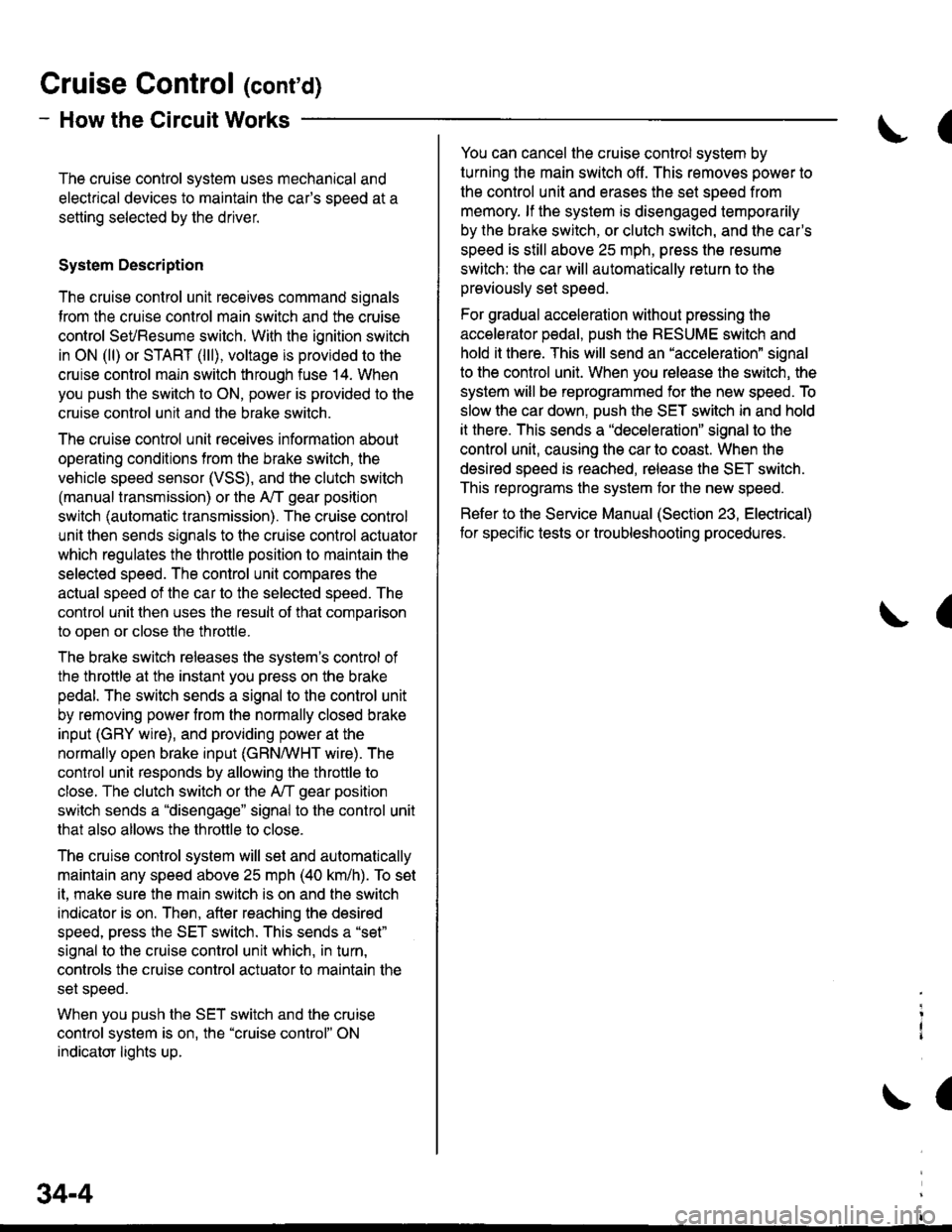
Gruise Control (cont'd)
- How the Circuit Works
The cruise control system uses mechanical and
electrical devices to maintain the car's sDeed at a
setting selected by the driver.
System Description
The cruise control unit receives command signals
from the crurse control main switch and the cruise
control SeVResume switch. With the ignition switch
in ON (ll) or START (lll), voltage is provided to the
cruise control main switch through fuse 14. When
you push the switch to ON, power is provided to the
cruise control unit and the brake switch.
The cruise control unit receives information about
operating conditions from the brake switch, the
vehicle speed sensor (VSS), and the clutch switch
(manual transmission) or the A,/T gear position
switch (automatic transmission). The cruise control
unit then sends signals to the cruise control actuator
which regulates the throttle position to maintain the
selected speed. The conlrol unit compares the
actual speed of the car to the selected speed. The
control unit then uses the result of that comoarison
to open or close the throttle.
The brake switch releases the system's control of
the throttle at the instant you press on the brake
pedal. The switch sends a signal to the control unit
by removing power from the normally closed brake
input (GRY wire), and providing power at the
normally open brake input (GRN/vVHT wire). The
control unit responds by allowing the throttle to
close. The clutch switch or the A,/T gear position
switch sends a "disengage" signal to the control unit
that also allows the throttle to close.
The cruise control system will set and automatically
maintain any speed above 25 mph (40 km/h). To set
it, make sure the main switch is on and the switch
indicator is on. Then, after reaching the desired
speed, press the SET switch. This sends a "set"
signal to the cruise control unit which, in turn,
controls the cruise control actuator to maintain the
set speed.
When you push the SET switch and the cruise
control system is on, the "cruise control" ON
indicator lights up.
34-4
(
You can cancel the cruise control system by
turning the main switch off . This removes power to
the control unit and erases the set speed from
memory. lf the system is disengaged temporarily
by the brake switch, or clutch switch, and the car's
speed is still above 25 mph, press the resume
switch: the car will automatically return to the
previously set speed.
For gradual acceleration without pressing the
accelerator pedal, push the RESUME switch and
hold it there. This will send an "acceleration" signal
to the control unit. When you release the switch, the
system will be reprogrammed for the new speed. To
slow the car down. oush the SET switch in and hold
it there. This sends a "deceleration" signal to the
control unit, causing the car to coast. When the
desired speed is reached, release the SET switch.
This reprograms the system tor the new speed.
Refer to the Service Manual (Section 23, Electrical)
tor specific tests or troubleshooting procedures.
(
a
Page 1946 of 2189
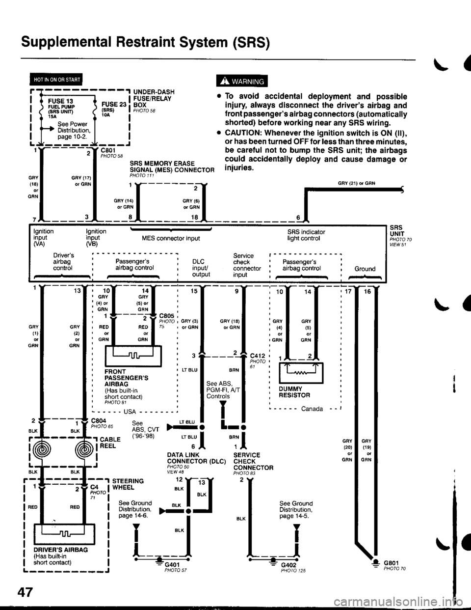
Supplemental Restraint System (SRS)
(
FUSE 13FUELPUUPFBA UMT)15A
See PowerDistibution,page 10-2.
FUSE 23(sRs)
c801PHOTO 58
SRS MEMORY ERASESTGNAL (MES) CONNECTORPHO|O 111
. To avoid accidental deployment and possible
iniury always disconnect the driver's airbag and
f ront passenger's airbag connectors (automatically
shorted) before working near any SRS wiring.
. CAUTION: Whenever the ignition switch is ON (tt),
or has been turned OFF for less than three minutes,
be caretul not to bump the SRS unit; the airbags
could accidentally deploy and cause damage or
iniuries.
UNDER-DASHFUSE/RELAYBOX
GFY 07)or GFN{18)
GFN
GFYt2l
GFN
GRY0)
GFN
2
ALK
J (ii
t\
GFY O4)or GRN
SRSUNIT
a
-ffiffi,*l-{
H!=";=_J
iffii'r:fi:*" i tH-
PHOIO 125short contact) | - FCqOtL_________J PHO|A 57
47
GAY (21) or GRN
lgnitionInput(VA)
Driver's
cont.ol
lgnitioninput(VB)MES connector inputSRS indicatorlighl control
Service t------check : Passengefs ;connector ; airbag control , GroundInpu , /+rr I pir-r
Passenger'sai|bag conlrol; prc..t rnpuv, Ourpul
14GRY(5) orGFN
rffi{{_ilil
i ffi i""'"1*"o,"'.1'' i lffil
ffirtu!-T:l
ir:r*::"."
ilstEl'{s6.e8'�
'"'Jl "Tl
, I oATA L|NK SERVTCE: CoNNECTOR (DLC) CHECK,J piarasa CONNECTORvtEw48