Page 1637 of 2189
Headlights/Front Turn
Signal/Parking Lights
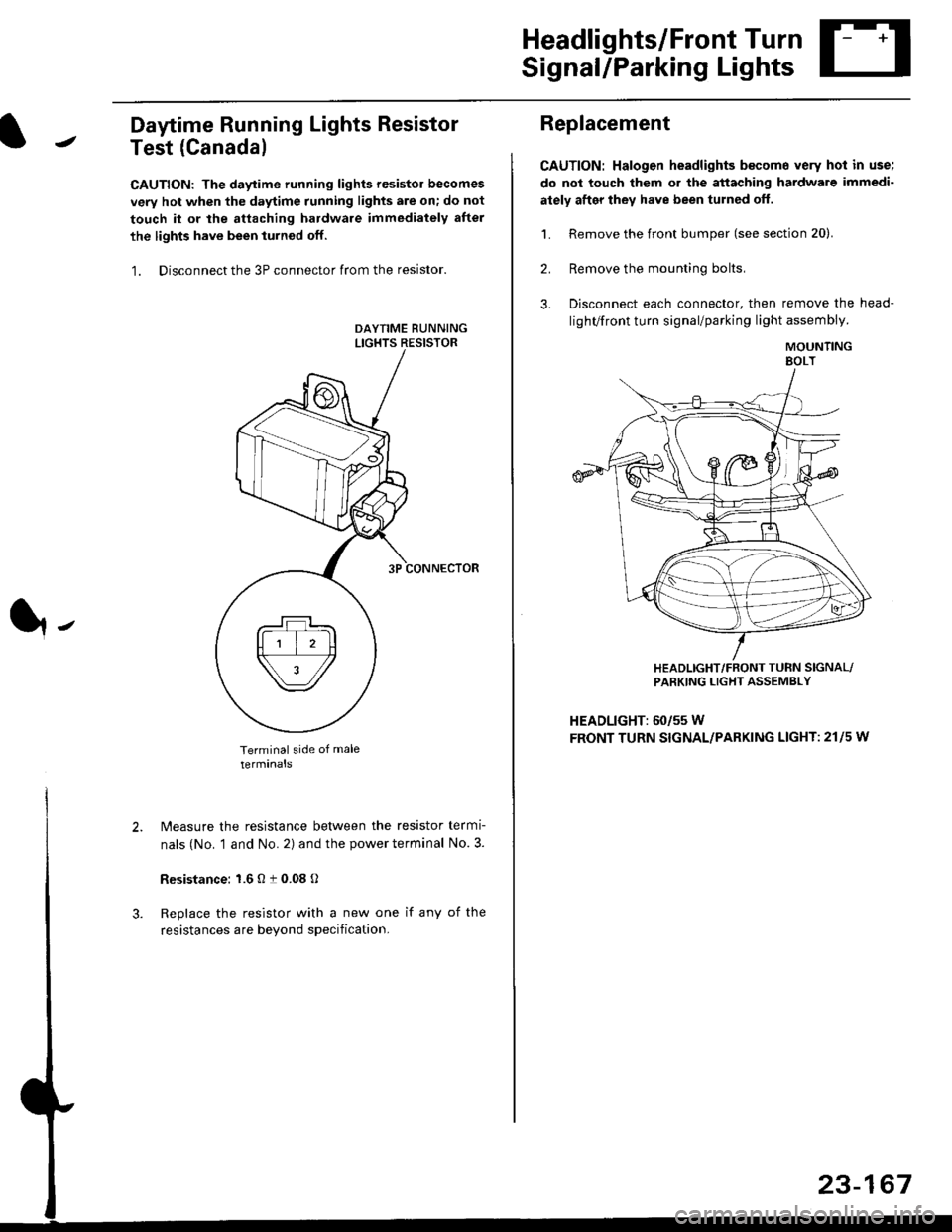
Daytime Running Lights Resistor
Test (Canada)
CAUTION: The daytime running lights resistor becomes
very hot when the daytime running lights are on; do not
touch il or the attaching hardware immediately after
the lights have been iurned off.
1. Disconnect the 3P connector from the resistor.
Terminal side of male
terminals
N4easure the resistance between the resistor termi
nals (No. 1 and No. 2) and the power terminal No. 3.
Resistance: 1.6 O t 0.08 O
Replace the resistor with a new one if any of the
resistances are beyond specification.
It-
Replacement
CAUTION: Halogen headlights b€come very hot in use;
do not touch them or the attaching hardware immedi-
ately after they have been turned off.
1. Remove the front bumper (see section 20).
2. Remove the mounting bolts,
3. Disconnect each connector, then remove the head-
lighVfront turn signal/parking light assembly.
MOUNTINGEOLT
HEADLIGHT/FRONT TUFN SIGNAL/PARKING LIGHT ASSEMBLY
HEADLIGHT: 60/55 W
FRONT TURN SIGNAL/PARKING LIGHT: 21l5 w
23-167
Page 1638 of 2189
Headlights
Adjustment
Eoforo adiu3ting th€ h.adlights:
. Park the vehicle on level surface.
. Make sure the tire prgssures are correct.
a The driver or someone who weighs the same should
sit in the driver's seat.
96 - 98 modols
1. Open the hood.
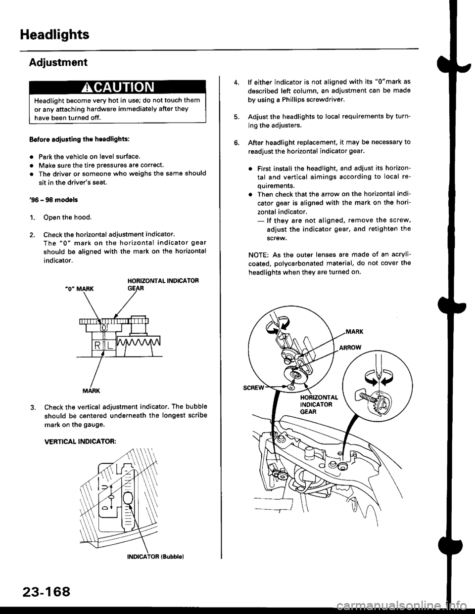
2. Check the horizontal adjustment indicator.
The "0" mark on the horizontal indicator gear
should be aligned with the mark on the horizontal
indicator.
HORIZONTAL INDICATOR
Check the vertical adjustment indicator. The bubble
should be centered underneath the longest scribe
mark on the gauge.
VERTICAL INDICATOR:
Headlight become very hot in use; do not touch them
or any attaching hardware immediately after they
have been turnsd off.
MARK
23-164
(Bubblol
lf either indicator is not aligned with its "0"mark as
described left column, an adjustment can be made
by using a Phillips screwdriver.
Adjust the headlights to local requirements by turn-
ing the adjusters.
After headlight replacement, it may bs necessary to
readjust the horizontal indicator gear.
. First install the headlioht, and adjust its horizon-
tal and vertical aimings according to local re-
quirements.
. Then check that the arrow on the horizontal indi-
cator gear is aligned with the mark on the hori-
zontal indicator.- lf they are not aligned, remove the screw,
adiust the indicator gear, and retighten the
screw.
NOTE: As the outer lenses are made ot an acryli-
coated, polycarbonated material, do not cover the
headlights when they are turned on.
Page 1640 of 2189
Headlights
Adjustment (cont'dl
Turn the low beams on.
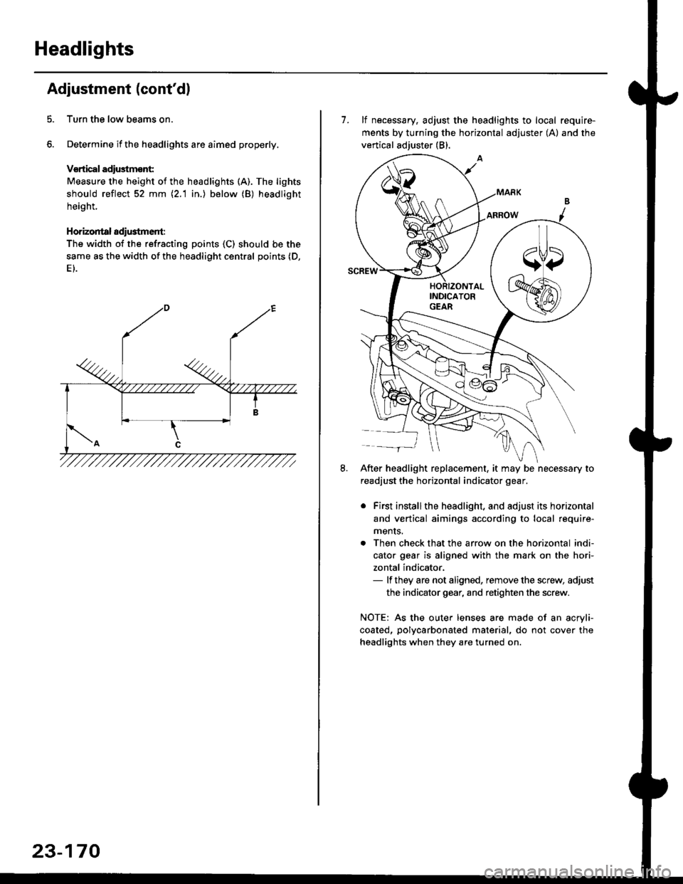
Determine if the headlights are aimed properly.
Vsrtical adiustmsnt:
Measure the height of the headlights (A). The lights
should reflect 52 mm \2.1 in.) below (B) headlight
height.
Horizontal adi$tment:
The width of the refracting points (C) should be the
same as the width of the headlight central points (D,
23-170
7. lf necessary, adjust the headlights to local require-
ments by turning the horizontal adjuster (A) and the
vertical adjuster (B).
After headlight replacement, it may be necessary to
readjust the horizontal indicator gear.
. First installthe headlight, and adjust its horizontal
and vertical aimings according to local require-
ments.
. Then check that the arrow on the horizontal indi-
cator gear is aligned with the mark on the hori-
zontal indicator,- lf they are not aligned, remove the screw, adjust
the indicator gear, and retighten the screw.
NOTE: As the outer lenses are made of an acryli-
coated, polycarbonated material, do not cover the
headlights when they are turned on.
Page 1813 of 2189
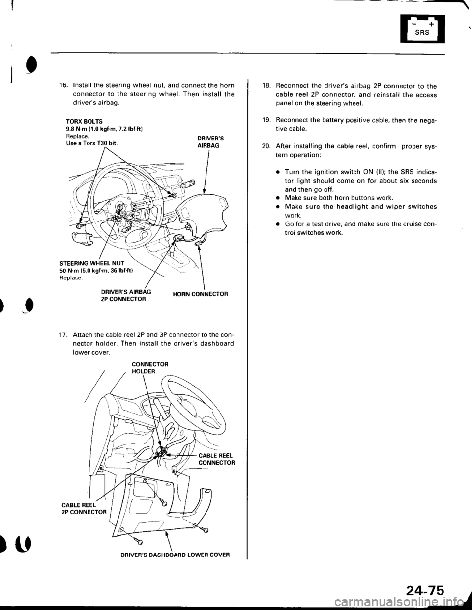
16. Install the steering wheel nut, and connect the horn
connector to the steering wheel. Then install the
driver's airbag.
TORX SOLTS9.8 N m 11.0 kgf m, 7.2 lbtftlReplace.Use a Torx T30 bit.
STEERING WHEEL NUT50 N.m 15.0 kgf.m,36lblft)Replace.
DRIVEB'SAIRBAG
DRIVER'S2P CONNECTOBHORN CONNECTOB
I
17.Attach the cable reel 2P and 3P connector to the con-
nector holder. Then install the driver's dashboard
lower cover.
)UDRIVER'S DASHBOARD LOWER COVER
24-75
18. Reconnect the driver's airbag 2P connector to the
cable reel 2P connector. and reinstall the accesspanel on the steering wheel.
19. Reconnect the battery positive cable, then the nega-
tive cable.
20. After installing the cable reel, confirm proper sys-
tem operation:
Turn the ignition switch ON (ll); the SRS indica-
tor light should come on for about six seconds
and then go off.
Make sure both horn buttons work.
Make sure the headlight and wiper switches
Go for a test drive, and make sure the cruise con
trol switches work.
a
a
Page 2066 of 2189
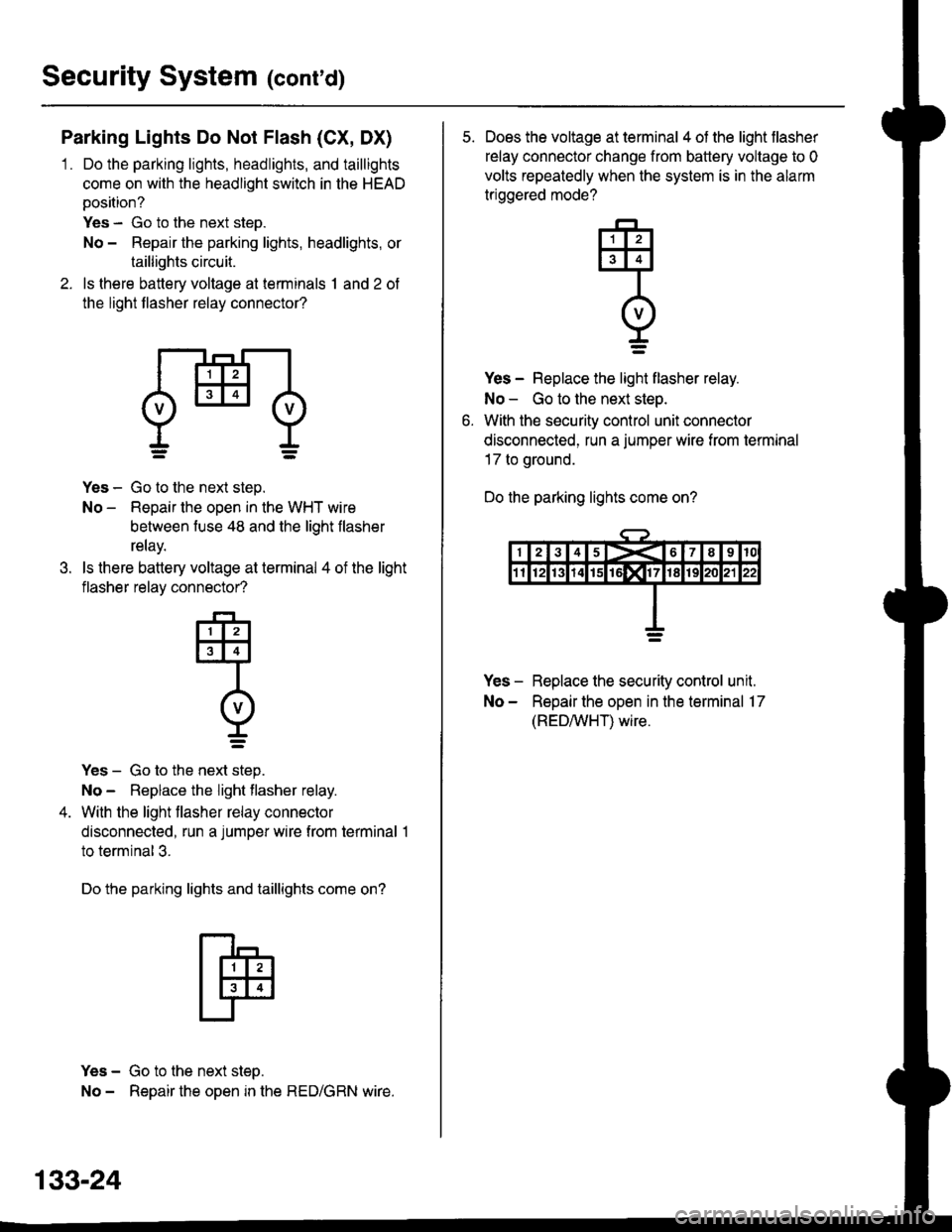
Security System (conrd)
Parking Lights Do Not Flash (CX, DX)
1 . Do the parking lights, headlights, and taillights
come on with the headlight switch in the HEAD
position?
Yes - Go to the next step.
No - Repair the parking lights, headlights, or
taillights circuit.
2. ls there battery voltage at terminals 1 and 2 of
the light flasher relay connector?
dHl
.t.
Yes - Go to the next step.
No - Repair the open in the WHT wire
between fuse 48 and the light flasher
relay.
ls there battery voltage at terminal 4 of the light
flasher relay connector?
-F-,
tlllJt3l4l
Intvl
r=
Yes - Go to the next step.
No - Replace the light flasher relay.
With the light flasher relay connector
disconnected, run a jumper wire from terminal 1
to terminal 3.
Do the parking lights and taillights come on?
Yes - Go to the next step.
No - Repair the open in the RED/GRN wire.
133-24
5. Does the voltage at terminal 4 of the light flasher
relay connector change from battery voltage to 0
volts repeatedly when the system is in the alarm
triggered mode?
Yes - Replace the light flasher relay.
No - Go to the next step.
With the security control unit connector
disconnected, run a jumper wire from termrnal
17 to ground.
Do the parking lights come on?
Yes - Replace the security control unit.
No - Repair the open in the terminal 17
(REDAIVHT) wire.
q
I=
Page 2067 of 2189
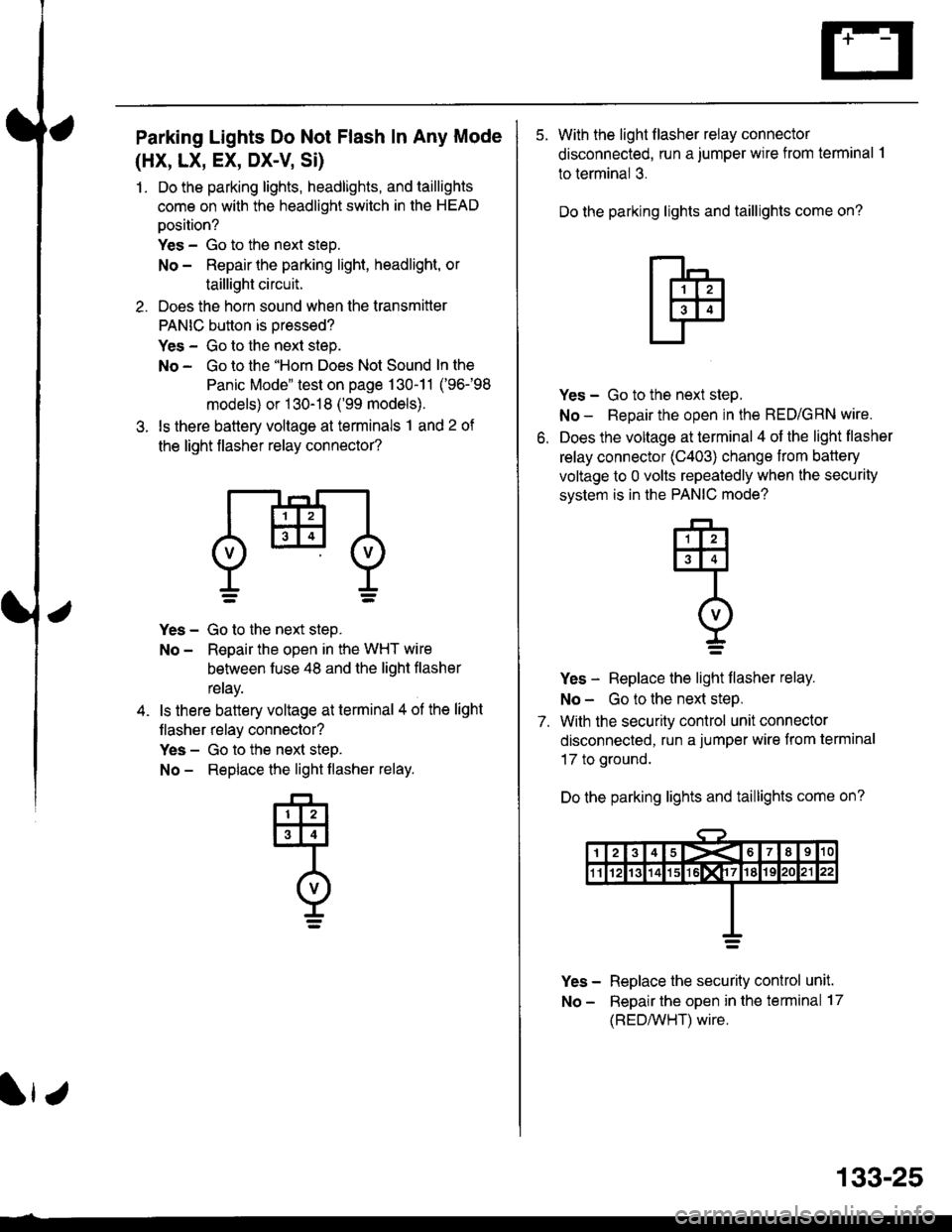
Parking Lights Do Not Flash In Any Mode
(HX, LX, EX, DX-V Si)
1. Do the parking lights, headlights, and taillights
come on with the headlight switch in the HEAD
oosition?
Yes - Go to the next steo.
No - Repair the parking light, headlight, or
taillight circuit.
2. Does the horn sound when the transmitter
PANIC button is oressed?
Yes - Go to the next step.
No - Go to the "Horn Does Not Sound In the
Panic Mode" test on page 130-11 ('96-98
models) or 1 30-18 ('99 models).
3. ls there battery voltage at terminals 1 and 2 of
the light flasher relay connector?
Yes - Go to the next step.
No - Reoair the open in the WHT wire
behveen fuse 48 and the liqht flasher
reray.
ls there battery voltage at terminal 4 ol the light
flasher relay connector?
Yes - Go to the next steD.
No - Replace the light flasher relay.
133-25
5. With the light flasher relay connector
disconnected, run a jumper wire from terminal .l
to terminal 3.
Do the parking lights and taillights come on?
o.
Yes - Go to the next step.
No - Repair the open in the RED/GRN wire.
Does the voltage at terminal 4 of the light flasher
relay connector (C403) change from battery
voltage to 0 volts repeatedly when the security
svstem is in the PANIC mode?
Yes - Replace the light flasher relay.
No - Go to the next steP.
7. With the security control unit connector
disconnected, run a jumper wire from terminal
17 to ground.
Do the parking lights and taillights come on?
Yes - Replace the security conlrol unit.
No - Repair the open in the terminal 17
(REDMHT) wire.
q
I=