1996 HONDA CIVIC fuel light
[x] Cancel search: fuel lightPage 379 of 2189

PGM-FI System
(From page 11-109)
Replace the sensor that causedthe light to go out.Does the N4lL go OFF?
Check fo. a short in the wi.os(VCC lines):':. Turn the ignition switch OFF.2. Disco n n ect the ECM/PCMconnector D (16P).
3. Check for continuity betweenbody ground and ECM/PCMconnector terminals D4 andD10 individually.
Ropair short to body groundin the wire betweon ECM/PCM {O4) and MAP s6n3or.Repair short to body groundin the wire between ECM/PCM lD10l, the TP sensor, theEGR valve lift sensor {D16Y5engine) and/or the Fuel tankpressure sensor {'96 Dl6Ygengine lcoupe),'97 D16Y7engine (coupe: KL model,sedan: KL (LXl model), '97
D16Y8 engine (coupe: allmodels, sedan: KL model. €8-allmodelsl.
ls there continuity?
Check tor rn open in the wires(lGP lines):1. Disconnect the fuel injectorsand IAC valve connectors,2. Turn the ignition switch ON (ll).3. Meas u re voltage betweenbody ground and ECM/PCMconnector terminals A11 and424 indivjdually.- Repair open in the wirels)between ECM/PCM (A11,A24land PGM-Fl main relay.- Check for poor connectionsor loose wiras at the PGM-FImain relay,- Test the PGM-FI mdin relavlsee pag6 11-237).
ls there battery vohage?
Check for an open in the wires(LG line3):1. Reconnect all sensor connectors.2. Reconnect the ECM/PCM con-nector D (16P).
3. Turn the ignition switch ON (ll).4. Measure vo ltage betweenbody ground and ECM/PCMconnector terminals Ag andA22 individually.
Repair open in the wirolglb€twe€n ECM/PCM {A9, A22} andG101 that had more than 1.0 V.
ls there less than 1.0 V?
Substitute 6 known-good ECM/PCM and r€check. lf symptom/indication 9o€s away, replacethe original ECM/PCM.
Engine Control Module/Powertrain Control Module (ECM/pCMl
('96 - 98 Models, '99 - 00 D16Y5 engine with M/Tl (cont,dl
ECM/PCM CONNECTOR D {16P}
Wire side of female terminals
ECM/PCM CONNECTOR A (32P}
Wire side of female terminals
11-110
LG1
VCCl {YEL/RED}
IGP 1{YEL/BLKI
2I11
1213l5t6Itt8t9202321
25272a2930
IGP 2(YEL/BLKIv) (l
{8RN/BLK)
I258tol1'12tt11t5l617t8t920232a
2A2330
LG2{8RN/8LK}
Page 380 of 2189
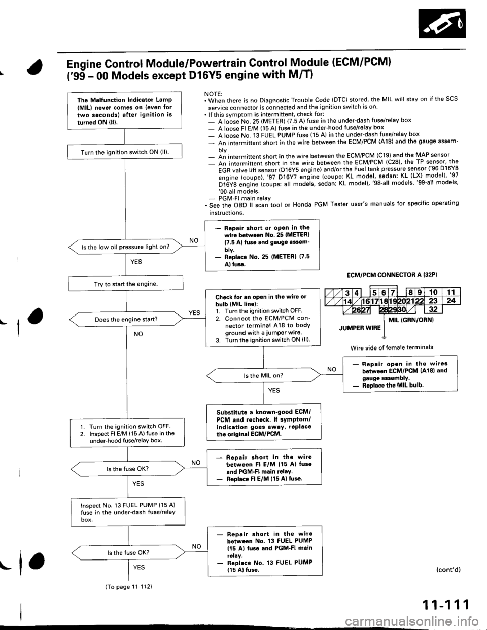
Engine Control Module/Powertrain Control Module (ECM/PCM)
('95 - 00 Models except Dl6Y5 engine with M/T)
NOTE:. When there is no Diagnostic Trouble Code lDTC) stored, the MIL will staY on if the SCS
seruice connector is connected and the ignition switch is on.. lf this symptom is intermittent, check for:- A loose No. 25 (METER) {7.5 A) fuse in the underdash fuse/relay box- A loose Fl E/M (15 Alluse in the undeFhood fuse/relay box- A loose No. 13 FUEL PUMPfuse (15 A) in the under-dash fuse/relay box- An intermittent shon in the wire between the ECM/PCM (A18) and the gauge assem'
- an intermittent short in the wire between the ECM/PCM (C19) and the MAP sensor- An intermittent short in the wire between the ECM/PCM {C28), the TP sensor, the
EGR valve lift sensor (D16Y5 engine) and/or the Fuel tank pressure sensor ('96 D16Y8
engine (coupe),'97 D16Y7 engine lcoupe: KL model, sodan: KL (LX) model)"g7
Dt6Y8 engine (coupe: all mod;ls, sedanl KL model),'98-all models,'99-al' models''00-all models.- PGM'FI main relay. See the oBD ll scan tool or Honda PGM Tester user's manuals for specific operating
instructrons,
ECM,/PCM CONNECTOR A I32PI
Wire side of {emale terminals
The Mrlfunction Indicator LamP{MlL) never comes on {even tor
two seconds) after ignition is
turned ON lll).
Turn the ignition switch ON lll).
- Repair shott or open in thowire bstwoon No. 25 IMETER)l?.5 A)tuse and gauga tsom_blv.- Reolace No. 25 (METERI (7.5
Alluse.
ls the low oil pressure light on?
Try to start the engine.
Check for an opon in the wire orbulb (MlL line):1. Turn the ignition switch OFF.2. Connect the ECM/PCM con'
nector terminal A18 to bodyground with a iumper wire.
3. Turn the ignition switch ON (ll)
Does the engine start?
- Repair open in tho wire3
betwoon ECM/PCM (A18) andgaugo .*tembly.- Rool.ce the MIL bulb.
Substitute a known-good ECM/
PCM and rochoc&. lf sYmptom/indication goes sw6y, repl.ce
tho original ECM/PCM.Turn the ignition switch OFF.Inspect Fl E/M (15 A)fuse in theunderhood Iuse/relay box.
Rop.ir short in the wirc
betwo€n Fl E/M (15 A) luso
and PGM-Fl mrin rGl.y.Reol.ce Fl E/M (15 A)tusa.
lnspect No. 13 FUEL PUMP {15 A}
luse in the under-dash fuse/relay
- Reoair short in the wiro
between No. 13 FUEL PUMP
115 Al luse sod PGM-FI mainrelay.- Reolace No. 13 FUEL PUMP115 A) tuse.
(To page 11 112)
(cont'd)
11-111
.f,
Page 726 of 2189
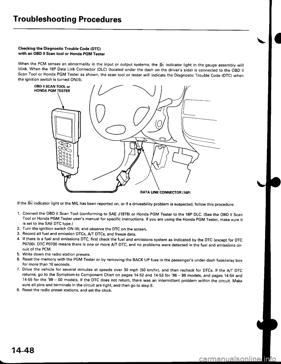
Troubleshootin g Procedures
Chccking the Diagnostic Trouble Code IDTC)with an OBD ll Scan tool or Honda PGM Tester
when the PCM senses an abnormality in the input or output systems, the pl indicator light in the gauge assembly willblink. When the 16P Data Link Connector (DLC) (located under the dash on the driver,s side) is connected to the OBD llScan Tool or Honda PGM Tester as shown, the scan tool or tester will indicate the Diagnostic Trouble Code (DTC) whenthe ignition switch is turned ON{ll).
lf the El indicator light or the MIL has been reported on, or lf a driveability problem is suspected, follow this procedure:
1. Connect the OBD ll Scan Tool (conforming to SAE J19781 or Honda PGM Tester to rhe 16p DLC. (See the OBD ll ScanTool or Honda PGM Tester user's manual for specific instructions. lf you are using the Honda PGM Tester, make sure itis set to the SAE DTC type.)
2. Turn the ignition switch ON (lll, and observe the DTC on the screen,3, Record all fuel and emission DTCS, A/T DTCS, and freeze data.4 lf there is a fuel and emissions DTC, first checkthe fuel and emissions system as indicated bythe DTC (except for DTCP0700). DTC P0700 means there is one or more A,/T DTC, and no problems were detected in the fuel and emissions cir-cuit of the PCM.
5. Write down the radio station oresets.
6. Reset the memory with the PGM Tester or by removing the BACK UP fuse in the passenger's under-dash fuse/relay boxfor more than 10 seconds.
7. Drive the vehicle for several minutes at speeds over 30 mph (50 km/hr), and then recheck for DTCS. lf the A"/T DTCreturns, go to the Symptom-to Component Chart on pages 14-52 and 14-53 for'96 - 98 models, and pages 14-54 and14-55 for the'99 - 00 models, lf the DTC does not return, there was an intermittent problem within the circuit. Makesure all pins and terminals in the circuit are tight, and then go to step g.
8. Reset the radio preset stations, and set the clock.
OBD ll SCAN TOOL orHONDA PGM TESTER
DAYA LINK CONNECTOR {16P}
14-44
Page 1471 of 2189

l'f .
Electrical
Special Toofs .,....................,23-2
Troubleshooting
Tips and Precautions ..............,.................... . 23-3
Five-step Troubleshooting .............. ......... . . 23-5
wire color codes ..........,23-5
Schematic Symbols ........,................... . . .. .... 23-6
Relay and Control Unit Locations
Engine Compartment ...,..................... ... .. . 23'7
Dashboard ......................23-8
Dashboard/Door ......... 23-12*Airbags ................. ....... Section 24
Air Conditioning ......... Section 21
Aftelnator ..........."""" """ 23-112
Anti-lock Brake System {ABS) Section 19*A/T Gear Position Indicator .....................,. .... ... 23-149
Automatic Transmission Svstem .... . ....... Section 14
Batterv ......... . . . ... ...... .......23-91
Blower controls .. . ... Section 2l
Charging System ....'...........23'112
Connector ldentilication and Wire Harness
Routing .................. ......23'13
Cruise Control ............,........23-240
Dash Lights Brightness Controller ............. ....... 23-180
Fan controfs "" 23'126
Fuel PumD ........ . ........ section 11
Fuses/Refay ...............,..,,.. 23'62
PGM-FI Control System ......................,....... Section 1 1
*Gauges
Circuit Diagram ....,.,.......23-131
Fuef Gauge ...........'.'.......23-142
Gauge/lndicator .. . .. 23-129
Ground Distribution .. . 23-75
Heatei controls .. . ..... Section 21*Horn................. ...............23-196
*tgnition Switch ....................23-89
lgnition System .......,.... 23-102
*lntegrated Control Unit ....................................... 23-156
fnterlock System ,........ . . , ,23-144
Lighting System . . . .. ......... 23-161
Lights, Exterior
Back-up Lights ..'............23'171
Brake Lights .................. 23'174
Daytime Bunning Lights (Canadal ............... 23'166
Front Parking Lights ......,................ .'. .......... 23-167
Front Turn Signal Lights .......... . . ............ ..,.23-167
Headtights ....".'....-... ..... 23'167
High Mount Brake Light ...................... ... .23'179
License Plate Lights ...... 23'176
Taitfights ................ .......23'171
lnterior Lights ..-.......,, . 23-142
Moonroof ..,.................,........ 23-235
Power Distribution ....... . . .23-61
Power Door Locks .......,,,. .23'251
Power Mirrors ,..............,.,...23'206
Power Relays ....... . ...... . . .. 23-86
Power Windows ............,,....23-220
Rear Window Defogger .......................... . . ... . . 23-2OO
Spark Plugs . ..... . ........ .....23-111
Slarting System ................23-93*stereo Sound Svstem ,................. ..... ... . ... ,.,.,,23'147'Supplemental Restraint System (SRS) ... . Section 24
Turn Signal/Hazard Flasher System .......'.'....-... 23-173
*Undel-dash Fuse/Relay Box ............,.................. 23-85
vehicfe soeed sensor (VSSI """" ""' 23-140+Wipers/Washers .........,.,.,...23-214
NOTE: Unless otherwise specified, references to auto-
matic transmission (Mf) in this section include the CVT.
Page 1486 of 2189

Connector ldentification and Wire Harness Routing
Engine Wire Harness lD16Y5, D16Y8 enginss): '96 - 98 models
Connector or
Torminal
Numbsr of
CavitissLocationConnects toNot€s
c 101c102c103c104c104c105c106c107c108c 109c110c111c112c113c114c115c116cl17c118c119c120cl21
c122c123cl23c124
c125
c127c12Ac129c130c131c132c 133c134c135
c136
c138c139c140c 141c142c 143c144cl44c145c'146cl47
10
1
22
14l4322l0I
2
2
2
2120
3l
14
14
1222
2
2
22
Left side of engine compartmentMiddle of engineMiddle of engineLeft side of engine companmentLeft side of engine compartmentMiddle of engineMiddle of engineMiddle of engineMiddle of engineMiddle of enginefvliddle of engineMiddle of engineMiddle of engineMiddle of engineMiddle of engineMiddle of engineMiddle of engineLeft side of engine compartmentMiddle of engineMiddle of engineMiddle of engineMiddle of engine
Middle of engineMiddle of engineMiddle of engineMiddle of engineMiddle of engineMiddle of engineMiddle of engineMiddle of engineMiddle of engineRight side of engine companmentBehind right kick panelUnder right side of dashUnder riOht side of dashUnder right side of dashUnder right side of dashUnder right side of dashUnder right side of dash
Under right side of dash
Under right side of dash
Middle of engineMiddle ot enginel iddle of engineMiddle of engineMiddle of ongineMiddle of engineLeft side of engine compartmentMiddle of engineMiddle of engineRight side of engine compartmentRight side of engine compartmentRight side of engine compartment
USACanada
Afi
USA
-' (A/r)
Main wire harness (C303)Crankshaft speed fluctuation (CKF) sensorEngine oil pressure switchAlternatorAlternatorNo. 'l fuel injectorNo. 2 fuel injectorNo.3 fuel injectorNo. 4 fuel injectorIAC valveThrottle position (TP) sensorl\4anifold absolute pressure (MAP) sensorIntake air temperature (lAT) sensorPower steering pressure {PSPI switchEVAP purge control solenoid valveJunction connectorJunction conn€ctorVehicle speed sensor {VSS}Countershaft speed sensorEngine coolant temp€rature (ECT) switch ADistributorEngine coolant temperature (ECT) sendingunrtEngine coolant temperature (ECT) sensorPrimary HO2S (sensor'l)Primary HO2S (sensor 1)Back-up light switchLock-up control solenoid valveSecondary HO2S (sensor 2)Mainshaft speed sensorLinear solgnoid valveShift control solsnoid valveStarter solenoidJunction connectorMain wire harnesE (C446)ECM/PCMPCMECMiPCMECM/PCMMain wire harness (C305)
Main wire harness (C305)
Main wire harness (C305)
Knock sensor (KS)IAC valveVTEC solenoid valveVTEC pressure switchEVAP control canister vent shut valveEGR control solenoid valveSecondary gear shaft speed sensorEGR valveEGR valveDrive pulley speed sensorSolenoid connector {CVT)Driven pulley speed sensor
*, (M/T)M/T*" INT\
*, tAtf)
NT:'96 model*,(A,/T):'97 - 98mooets
moqets
M/T
-1 (l,/T)*, (A,/T)-,(4,/T)*1 {M/T)*, (A,/T)*1 (CW)*, (A,T)
T101r102Left side of engine companmentRight side of engine companmentAlternatorUnder-hood fuse/relay boxG 101Middle of engineEngine ground, via engine wire harness
2
*1: Dl6Y5 engine*2: D16Y8 engine*3: D16Y5 (Ay'T), D16Y8 engines
3-16
Page 1488 of 2189
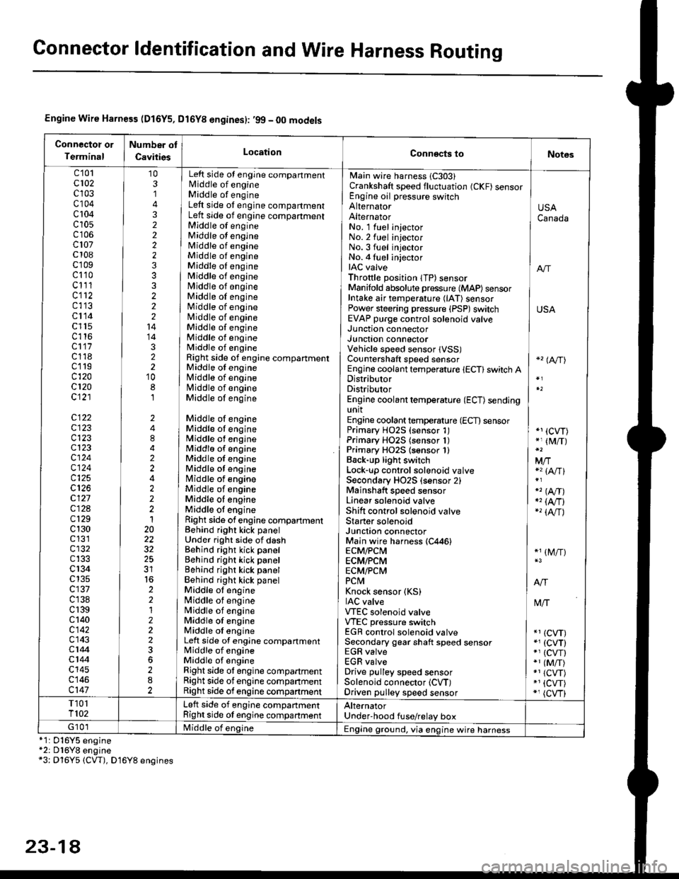
Gonnector ldentification and Wire Harness Routing
Engine Wire Harness (D16Y5, Dl6Yg engines): ,99 - 00 models
Connectot or
Terminal
Number ot
CavitiesLocationConn€cts toNotes
c'101cl02c103c104c 104c10s
c107c 108c'r09c110c111cl12c113cl14c l15c116cl17c118c119c120cl20c121
c122c123c123cl23cl24c124c125
c127c12Ac129c 130c131cl32c133c 134c135c137c138c 139c 140c142c143c144cl44c145c146c147
103,]
322223332221414322'10
8,l
2484224222120
32
2212223
282
No. 1 luel injector INo.2 fuel injectorNo.3 fuel injector ]No. 4 fuel injector iIAC valve I anThrottle position lTP) sensorManifold absolute pressure {MAP) sensor IIntake air temperature (lAT) sensor IPower steering pressure (PSP)switch USAEVAP purge control solenoid valve ]
Main wire harness 1C303)Crankshaft speed fluctuation (CKF) sensorEngine oil pressure switchAlternatorAlternator
Left side ot engine compartmentlvliddle of engineMiddle of engineLeft side ot engine compartmentLeft side of engine compartmentMiddle of engineMiddle ot engineMiddle of engineMiddle of engineMiddle oI engineMiddle of engineMiddle of engineMiddle of engineMiddle of engineNliddle of engineMiddle of engineMiddle of engineMiddle of engineRight side of engine compartmentMiddle of engineMiddle of engineN4iddle of engineMiddle of engine
Middle of engineMiddle ot engineMiddle ot engineMiddlo of engineMiddle of engineMiddle ot enginelrliddle of engineMiddle of engineMiddle oI engineMiddle ot engineRight side of engine compartmenlBehind right kick panelUnder right side of dashBehind right kick panelBehind right kick panelBehind righr kick panelBehind right kick panelMiddle ot engine[,liddle of engineN4iddle of engineMiddle of engineMiddle oI engineLeft side of engine compartmentMiddle of engineMiddle of engineRight side ol engine compartmentRight side of engine companmentRight side of engine compartment
USACanada
Junction connectorJUnct|On COnnectorVehicle speed sensor lVSS)Countershaft speed sensorEngine coolant temperature {ECT} switch ADistributorDistributorEngine coolant temperature (ECT) sendingunitEngine coolant temperature (ECT) sensorPrimary H02S (sensor 1)Primary HO2S (sensor 1)Primary HO2S lsensor 1)Back-up light switchLock'!p control solenoid valveSecondary HO2S (sensor 2)Mainshaft speed sensorLinear solenoid valveShift control solenoid valveStarter solenoidJunction connectorMain wire harness (C446)ECM/PCMECM/PCMECM/PCMPCtvtKnock sensor (KS)IAC valveVTEC solenoid valveVTEC pressure switchEGR control solenoid valveSecondary gear shaft speed sensorEGR valveEGR valveDrive pulley speed sensorSolenoid connector (CVT)Driven pulley speed sensor
*'� (A/TI
*1 (CVT)*, (M/T)
Mfia (A/Tl
" (A,/T)., (4,/r)-'� {AlrJ
*1 (M/T)
tvliT
*1 (CVT)*, (cvT)*' (cw)*1 (MiT)*1 {CVT)*1 {CVT)*, (cvr)
T101T102Left side of engine companmentRight side ot engine companmentAlternatorUnder'hood fuse/relay boxG 101Middle of englne IEngine ground, via engine wire harness*1: 016Y5*2: D16Y8*3: Dl6Y5
engineengine(CW), D16Y8 engines
23-14
Page 1490 of 2189
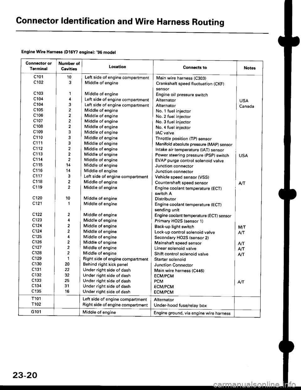
Gonnector ldentification and Wire Harness Routing
Engine Wire Harness {D16Y7 engine}: '96 model
Conneclor or
Terminal
Number ot
CavhiesLocationConnects toNotes
c101
c102
c 103
c104
c104
c105
c'r06
c107
c 108
c 109
c110
c111
c112
c l13
c't14
LttS
cl16
cl17
c118
cl19
c120
c121
c123
c124
c124
c125
c126
c't27
c12a
c129
c130
c131
c132
c133
c134
c135
10
1
4
5
'14
14
10
1
,,
2
2
1
22
31
16
No. 1 fuel injector INo. 2 fuel injector
No. 3 fuel injector INo,4 fuel injector
IAC valve l
Throttle position (TP)sensor IManifold absolute pressure (MAP) sensorIntake ai. temperature (lAT) sensor ]Power steering pressure (PSP) switch I USAEVAP purge control solenoid valve IJunction connector
Junction connector IVehicle speed sensor (VSS) |Countershaft speed sensor AlTEngine coolant temperature (ECT) I
Main wire harness (C303)
Crankshaft speed fluctuation (CKF)
sensor
Engine oil pressure switch
Alternator
Alternator
switch A
Distributor
Engine coolant temperature (ECT)
sending unit
Engine coolant temperature lECT) sensor
Primary H02S (sensor 1)
Back-up light switch
Lock-up control solenoid valve
Secondary HO2S (sensor 2)
Mainshaft speed sensor
Linear solenoid valve
Shift control solenoid valve
Staner solenoid
Junction Connector
Main wire harness {C446)ECM/PCM
PCM
ECM/PCM
ECM/PCM
Left side of engine compartment
Middle of engine
Middle of engine
Left side of engine compartment
Left side of engine compartment
Middle of engine
Middle of engine
Middle of engine
Middle of engine
Middle of engine
Middle of engine
Middle of engine
Middle of engine
Middle of engine
Middle of engine
Middle of engine
Middle of engine
Left side of engine compartment
Middle of engine
Middle of engine
Middle of engine
Middle of engine
Middle of engine
Middle of engine
Middle of engine
Middle of engine
Middle of engine
Middle of engine
Middle of engine
Middle of engine
Right side of engine compartment
Behind right kick panel
Under right side of dash
Under right side of dash
Under right side of dash
Under right side of dash
Under right side of dash
USA
Canada
M/T
AtJ
Afi
T101
T102
Left side of engine compartment
Right side of engine compartment
Alternator
Under-hood fuse/relay box
G101Middle of engineEngine ground, via engine wire harness
23-20
Page 1492 of 2189
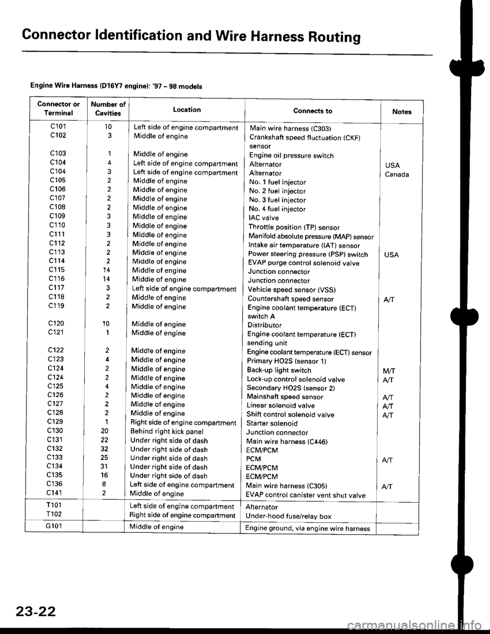
Connector ldentification and Wire Harness Routing
Engine Wire Harness {Dt6Y7 enginel: '97 - 9g models
Connectot or
Terminal
Number of
CsvitiesLocationConnects toNotes
c 101
c102
c103
c104
c104
c105
c106
c107
c 108
c109
cl10
clll
c112
cl13
cl14
c115
c1 l6
c117
c118
cl 19
cl20
c121
c122
c123
cl24
c124
c125
c126
c127
c128
c129
c 130
c 131
c132
c134
c135
cl41
10
1
2
10
I
2
2'>
4
t
20
3r
2
No. l fuel injector
No.2 fuel injector
No. 3 fuel injector INo. 4 fuel injector
IAC valve ]Throttle position (TP) sensor IManifold absolute pressure (MAP) sensorIntake air temperature (lAT) sensor ]Power steering pressure (PSp) switch I USAEVAP purge control solenoid valve
Junction connector IJunction connector IVehicle speed sensor (VSS)
Countershaft speed sensor I enEngine coolant temperature (ECTI
Main wire harness (C303)
Crankshaft speed fluctuation (CKF)
sensor
Engine oil pressure switch
Alte|'nator
Alternator
switch A
Distributor
Engine coolant temperature (ECT)
sending unit
Engine coolant temperature (ECT) sensor
Primary HO2S (sensor 1)
Back-up light switch
Lock-up control solenoid valve
Secondary H02S (sensor 2)
Mainshaft speed sensor
Linear solenoid valve
Shift control solenoid valve
Staner solenoid
Junction connector
Main wire harness (C446)
Left side of engine compartment
Middle of engine
Middle of engine
Left side of engine compartment
Left side of engine compartment
Middle of engine
Middle of engine
Middle of engine
Middle of engine
Middle of engine
Middle of engine
Middle of engine
Middle of engine
Middle of engine
Middle of engine
Middle of engine
Middle of engine
Left side of engine compartment
Middle of engine
Middle of engine
Middle of engine
Middle of engine
Middle of engine
Middle of engine
Middle of engine
Middle of engine
Middle of engine
Middle of engine
Middle of engine
Middle of engine
Right side of engine compartment
Behind right kick panel
Under right side of dash
Under right side of dash
Under right side of dash
Under right side of dash
Under right side of dash
Left side of engine compartment
Middle of engine
USA
Canada
Mtr
AIT
ECM/PCM
PcM I ArrECM/PCM
ECM/PCM
Main wire harness {C305) | AftEVAP control canister vent shut valve
T 101
r102
Left side of engine compartment
Right side of engine companment
Alternator
Under-hood fuse/relay box
G 101Middle of engineEngine ground, via engine wire harness
23-22