Page 1152 of 2189

Rear Damper
Disassembly/lnspection (cont'dl
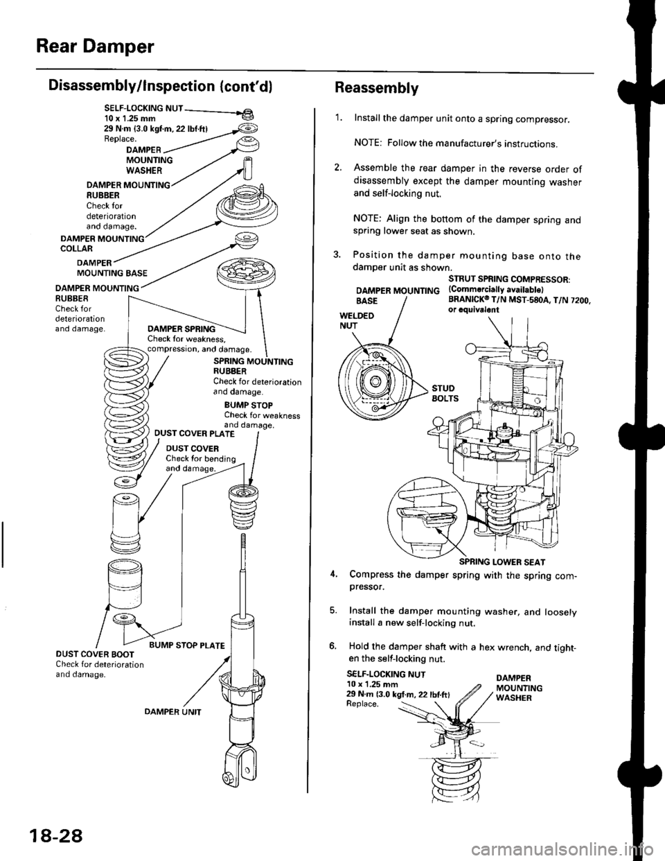
SELF-LOCK|NG NUT - el10 x 1.25 mm v
29 N.m {3.0 kst'm, 22 lbf.ftlReplace.
DAMPEBMOUNTINGWASHER
DAMPER MOUNTING8U8BERCheck tordeteriorationano oamage.
DAMPERCOLLAR
DAMPERMOUNTING BASE
OAMPER MOUNTING
DAMPER SPRINGCheck lor weakness,compression, and damage.
SPRING MOUNTINGRUBBERCheck for deteriorationano oamage.
BUMP STOPCheck for weaknessand damage,
BUBBESCheck fordeteriorationano oamage.
OUST COVER PLATE
DUST COVERCheck lor bending
DUST COVER BOOTCheck for deteriorationand damage.
18-2A
OAMPER UNITReplace. :
Reassembly
1.Install the damper unit onto a spring compressor.
NOTE: Followthe manufacturer's instructions.
Assemble the rear damper in the reverse order ofdisassembly except the damper mounting washer
and self-locking nut.
NOTE: Align the bottom of the damper spring andspring lower seat as shown.
Position the damper mounting base onto thedamoer unit as shown.
SIRUT SPRING COMPRESSOR:
DAMpERMOUNTTNG (Commerciattyavaitabtel
BRANICKO T/N MST-580A, T/N 7200.or cquivalont
Compress the damper spring with the spring com-pressor.
Install the damper mounting washer, and looselyinstall a new self-locking nut.
Hold the damper shaft with a hex wrench, and tight-en the self-locking nut.
SELF-LOCKING NUTDAMPER10 x 1,25 mm29 N m 13.0 kgt.m, 22 lbtftlMOUNTINGWASHER
Page 1429 of 2189

Description
Outline
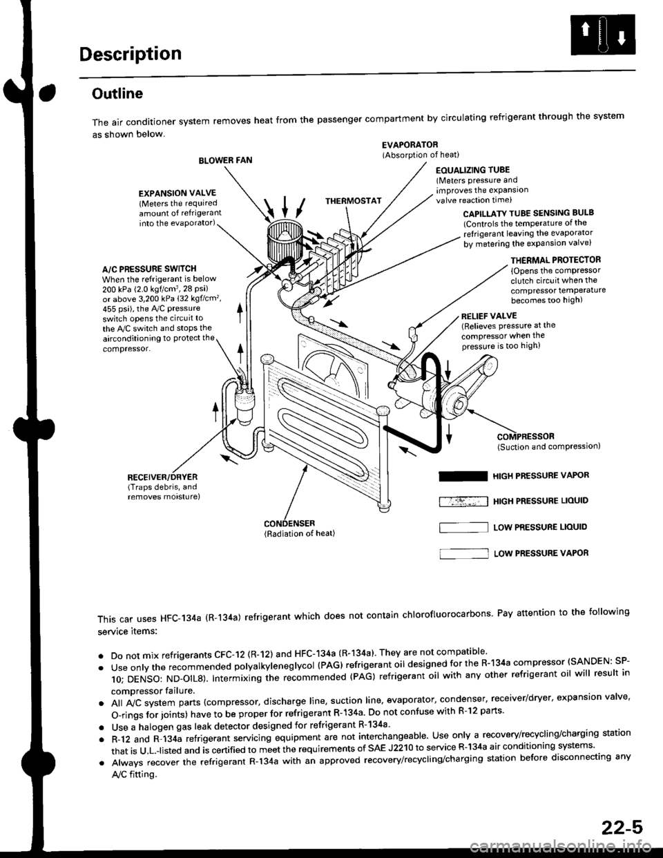
The air conditioner system removes heat from the passenger compartment by circulating refrigerant through the system
as shown below.
BLOWER FAN
EVAPORATOR(Absorption of heati
EOUALIZING TUBE(Meters pressure andimproves the expansionvalve reaction time)
into the evaporator)CAPILLATY TUBE SENSING BULB
lControls the temPerature of the
ref rigerant leaving the evaporator
by metering the expansion valve)
/\
THERMOSTAT
A/C PRESSURE SWITCH
When the refrigerant is below
200 kPa (2.0 kgtcm'�,28 Psi)or above 3,200 kPa 132 kgflcm',
455 psi), the Ay'C pressure
switch opens the circuit to
the A,/C switch and stops the
EXPANSION VALVE(Meters the requiredamount of refrigerant
airconditioning to Protect the
compressor.
RECEIVER/DRYER(Traps debris, andremoves morsturel
THERMAL PROTECTOR
{Opens the comPressorclutch circuit when the
compressor temPeraturebecomes too high)
RELIEF VALVE(Relieves pressure at the
compressor when thepressure is too high)
(Radiation of heat)
I
f-r-�-; I
(Suction and comPression,
HIGH PRESSURE VAPOR
HtGH PRESSUBE LIOUID
LOW PRESSURE LIOUID
This car uses HFC-134a (R-134a) refrigerant which does not contain chlorofluorocarbons Pay attention to the following
service items:
. Do not mix refrigerants CFC-12 (R-12) and HFC-134a (R-134a)' They are not compatible'
. Useonlythe recommended polyalkyieneglycol (PAG) refrigerant oil designedforthe R-134a compressor (SANDEN: SP-
10; DENSO: ND_OIL8). Intermixing ihe re-commended (pAG) refrigerant oil with any other refrigerant oil will result in
compressor failure.
. All A,,ic system parts {compressor, discharge line, suction line, evaporator, condenser, receiver/dryer, expansion valve'
O-rings for joints) have to be proper for refrigerant R- 134a Do not confuse with R-l2 parts'
. Use a halogen gas leak detector designed for refrigerant R-134a
. R-12 and R-134a refrigerant servacing equipment are not interchangeable. Use only a recovery/recycling/charging station
that is u,L.-listed and is certified to meet the requirements of sAE J2210 to service R-134a air conditioning systems'
. Always recover the refrigerant R-134a with an approved recovery/recycling/charging station before disconnecting any
A,/C fitting.
S]
22-5
Page 1576 of 2189

lgnition System
Distributor Replacement
Removal:
1. Disconnect the connector from the distributor.
2. Disconnect the ignition wires from the distributor
ignition {Dl) cap.
3. Remove the mounting bolts from the distributor,
then remove the distributor from the cylinder head.
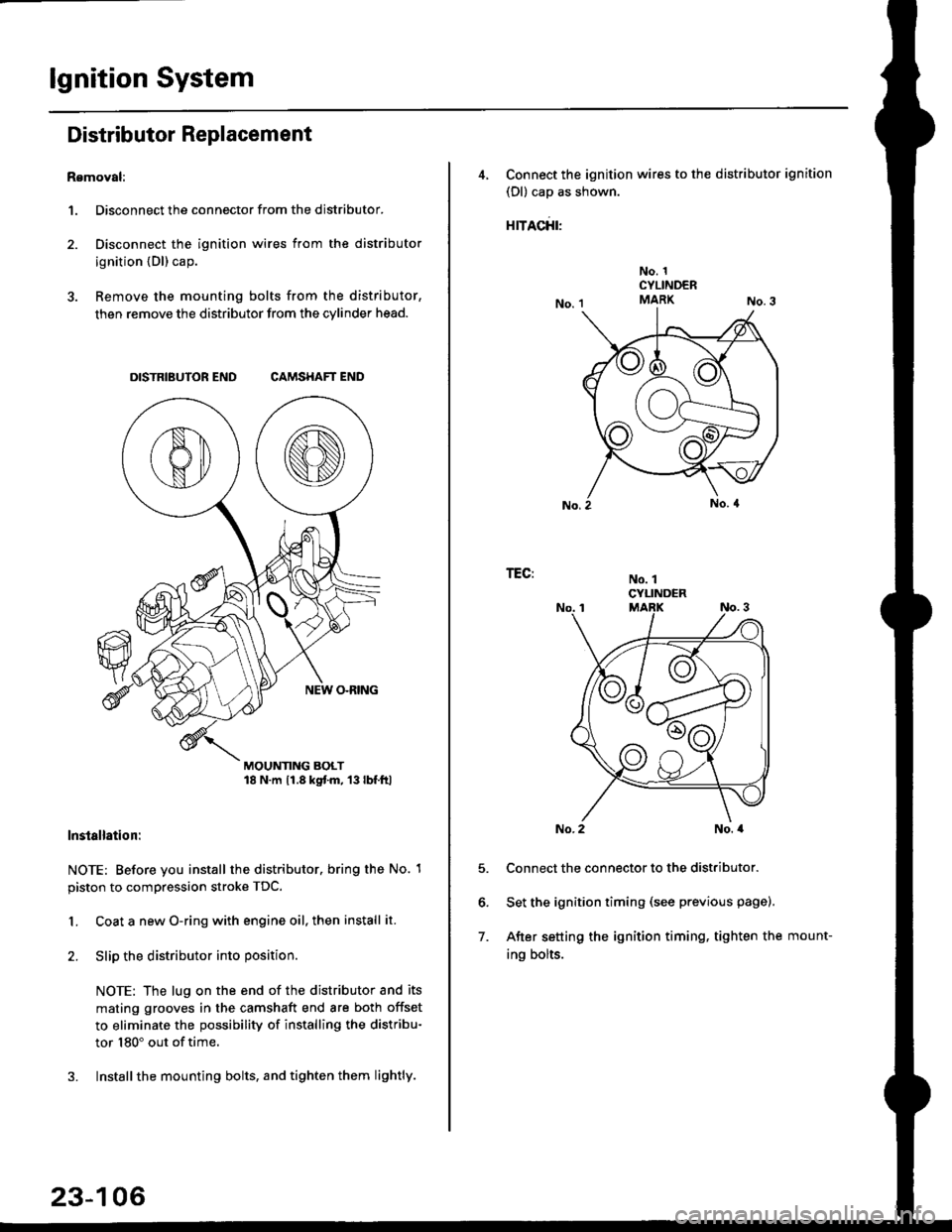
DISTRIBUTOR END CAMSHAFT END
MOUNTING BOLT18 N.m 11.8 kgtm, 13lbf.ltl
lnstallation:
NOTE: Before you install the distributor. bring the No. 1
piston to compression stroke TDC.
1. Coat a new O-ring with engine oil, then install it.
2. Slip the distributor into position
NOTE: The lug on the end of the distributor and its
mating grooves in the camshaft end are both offset
to eliminate the possibility of installing the distribu-
tor 180" out of time.
3. Installthe mounting bolts, and tighten them lightly.
23-106
4, Connect the ignition wires to the distributor ignition
(Dl) cap as shown.
rracfit'
No. 1CYLINDERMARK
No. 1CYLINDER
TEG:
5.
6.
7.
No. 2No. a
Connect the connector to the distributor.
Set the ignition timing (see previous page).
After setting the ignition timing, tighten the mount-
ing bolts.