Page 198 of 2189

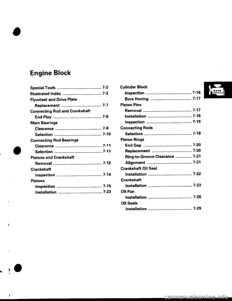
Engine Block
Speciaf Tools ..........." 7-2
lllustlated Index ...................."..'.......... 7-3
Flywheel and Drive Plate
Repf acement """'.' 7-7
Connecting Rod and Crankshaft
End Play ..........."....7-8
Main Bearings
Clearance ............... 7-9
Selection ................7-10
Connecting Rod Bearings
clearance ....'.......... 7-11
Selection ................ 7-11
Pistons and Crankshaft
Removaf ................. 7 -12
Crankshaft
Inspection ."".........7-14
Pistons
Inspection ......"'.....7-15
fnstaffation .............7-23
Cylinder Block
lnspec'tion ..............7-16
Bore Honing ..........7-17
Piston Pins
Removal ...,...........'.7-17
lnstallation .............7-18
Inspection .'............7-19
Connecting Rods
Selection ................7-18
Piston Rings
End Gap ..........".."' 7'2O
Repfacement .........7-2O
Ring-to-Groove Clearance ...........'.'. 7 -21
Afignment .......""'.. 7'21
Crankshaft Oil Seal
fnstaffation .............7-22
Crankshaft
fnstaffation ..-.-..'.".' 7'23
Oil Pan
lnstallation .............7-26
Oil Seals
fnstaffation ....""""' 7-29
r-f
Page 203 of 2189

lllustrated Index
(cont'd)
NOTE: New rod bearings must be selected by matching connecting rod assembly and crankshaft(see page 7,11).identification markings
Lubricate all internal parts with engine oil duringreassembtv.
PISTON INSTALLATION DIRECTION:
EXHAUST
4\/=\6\z\
\e/!rqrf/
INTAKE
PISTON RINGSReplacement. page 7-20Measurement, pages 7 20 andj-21Alignment, page 7-21
PISTON PINRemoval, page 7,17Installation, page 7-18Inspection, page 7,19
CONNECTING RODEnd play, page 7-8Selection, page 7,18
CONNECTING RODBEARINGSClearance, page 7 11Selection, page 7-11
CONNECTING ROD BEARING CAPInstallation, page 7-23NOTE: lnstall caps so thebearing recess is on thesame side as the recessin the rod.
PISTONInspectron, page 7-15NOTE: Betore removing the piston, inspect thetop of the cylinder bore for carbon build-up orridge. Bemove ridge if necessary, page 7-13
ENGINE BLOCKCylinder bore inspection, page 7-16Warpage inspection, page 7,'16Cylinder bore honing, page 7,17
Inspect top of each cylinder borefor carbon build-up or ridgebefore removing piston.Remove ridge if necessary, page 7-13
CONNECTING ROD CAP NUT816A2 €ngin6:9 x 0.75 mm{0 N.m (4.1 kgt m, 30 tbf.ftlD16Y5, Dl6Y7. D16Y8 engines:8 x 0.75 mm3l N.m {3.2 kg{.m,23 tbt.fr)Apply engine oiltothe bolt threads.NOTE: After torquing each bearingcap, rotate crankshaft tocheck for binding.
7-6
Page 209 of 2189
Pistons and Crankshaft
Removal
1. Remove the oil pan assembly.
2. Remove the right side cover.
816A2 engine
D16Y5, Dl6Y7, D16Y8 ongines
RIGHT SIDE
7-12
\
3. Remove the oil screen.
4. R€move the oil pump.
816A2 engin€
OIL SCREEN
D16Y5, D1oyr, D16Y8 engin.s
O-RINGReplace.
5, Remove the baffle plate (816A2 engine).
OIL PUMP
Page 214 of 2189

Cylinder BlockPiston Pins
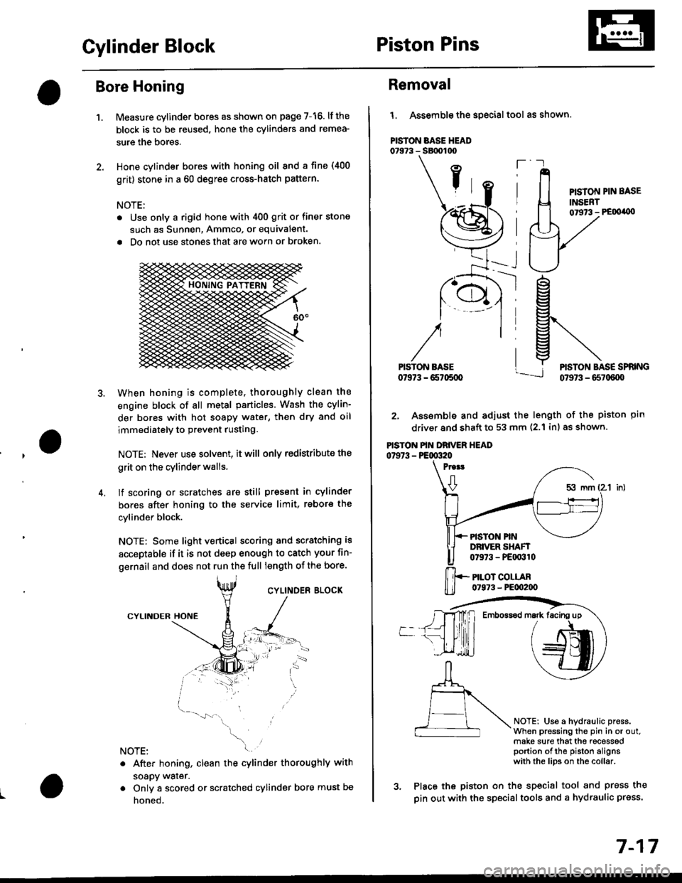
Bore Honing
1.Measure cylinder bores as shown on page 7-16. lf the
block is to be reused, hone the cylinders and remea-
sure the bores.
Hone cylinder bores with honing oil 8nd a fine (400
grit) stone in a 60 degree cross-hatch pattern.
NOTE:
. Use only a rigid hone with 400 grit or finer stone
such as Sunnen, Ammco, or equivalent.
. Do not use stones lhat are worn or broken.
When honing is complete, thoroughly clean the
engine block of all metal particles. Wash the cylin-
der bores with hot soapY water, then dry and oil
immediately to prevent rusting.
NOTE: Never use solvent. it will only redistribute the
grit on the cylinder walls.
lf scoring or scratches are still present in cylinder
bores after honing to the service limit, rebore the
cylinder block.
NOTE: Some light vertical scoring and scratching is
acceptable if it is not deep enough to catch your fin-
gernail and does not run the full length of the bore.
CYLINOES BLOCK
CYLINDER
NOTE:
. After honing, clean the cylinder thoroughly with
soapy warer.
. Onlv a scored or scratched cylinder bore must be
noneo.
Removal
l. Assemble the special tool as shown.
PISTON BASE HEAD07973 - SBtx)too
ft
PISTON PIN BASE
INSERT01973 - PE00'0)
ptn
NOTEi Us6 a hydraulic press.When pressing the pin in or out.make sure that the recesssdportion of the piston alignswith the lips on the collar.
rg
g\
lj*N*,""
2. Assemble and adjust the length of the piston
driver and shaft to 53 mm (2.1 inl as shown.
PISTON PIN DRIVER HEAD07973 - PE00320
Proat
0
PISTON PINDRIVER SHAFT0t973 - PEqr310
PILOT COLLAR07973 - PE00200
3. Place the piston on the sp€cial tool and press the
pin out with the special tools and a hydraulic press.
Emboss6d mark facing up
7-17
Page 1462 of 2189

Compressor (DENSOI
Replacement (cont'd)
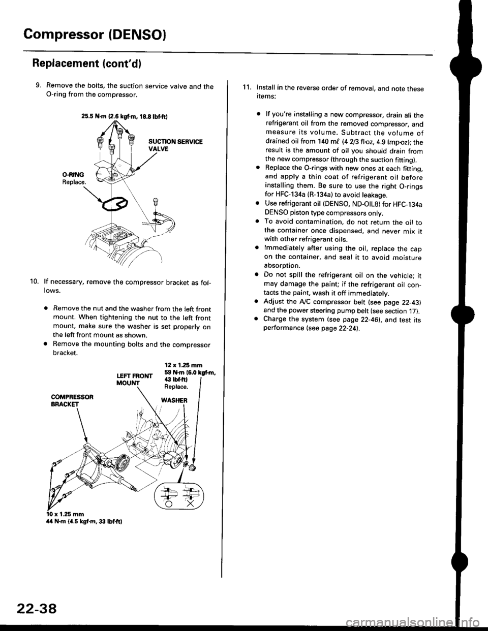
9. Remove the bolts, the suction service valve and theO-ring from the compressor,
lf necessary, remove the compressor bracket as fol-lows.
. Remove the nut and the washer from the left frontmount. When tightening the nut to the left frontmount, make sure the washer is set p.operly onthe left front mount as shown.
a Remove the mounting bolts and the compressor
bracket.
12 x 1,25 rnm59 N.m 16.0 kgfrm,
10.
LEFT FRONTMOUNT€ rbf.fi)Roplace.
WASHEB
x 1.25 mm
2s.5 N.m {2.6 kgf.m. 18.8 tbtttl
4/r N.m {4.5 kgf.m, 33 lbt ft}
22-3A
1 1. Install in the reverse order of removal, and note thesertems:
lf you're installing a new compressor. drain all therefrigerant oil from the removed compressor. andmeasure its volume. Subtract the volume ofdrained oil from '140 ml (4 28 fl{,z, 4.9 lmpoz); theresult is the amount of oil you should drain fromthe new compressor (through the suction fifting).Replace the O-rings with new ones at each fining,and apply a thin coat of refrigerant oil beforeinstalling them. Be sure to use the right O,ringsfor HFC-134a (R-134a) to avoid leakage.
Use refrigerant oil {DENSO, ND-OtL8) for HFC-134aDENSO piston type compressors only.To avoid contamination, do not return the oil tothe container once dispensed, and never mix itwith other refrigerant oils.
lmmediately after using the oil, replace the capon the container, and seal it to avoid moisture
absorption.
Do not spill the refrigerant oil on the vehicle; itmay damage the paint; if the refrigerant oil con-tacts the paint, wash it off immediatelv.
Adjust the ly'C compressor belt (see page 22-43)and the power steering pump belt (see section 17).Charge the system (see page 22-46), and test itsperformance (see page 22-24!..
Page 1576 of 2189

lgnition System
Distributor Replacement
Removal:
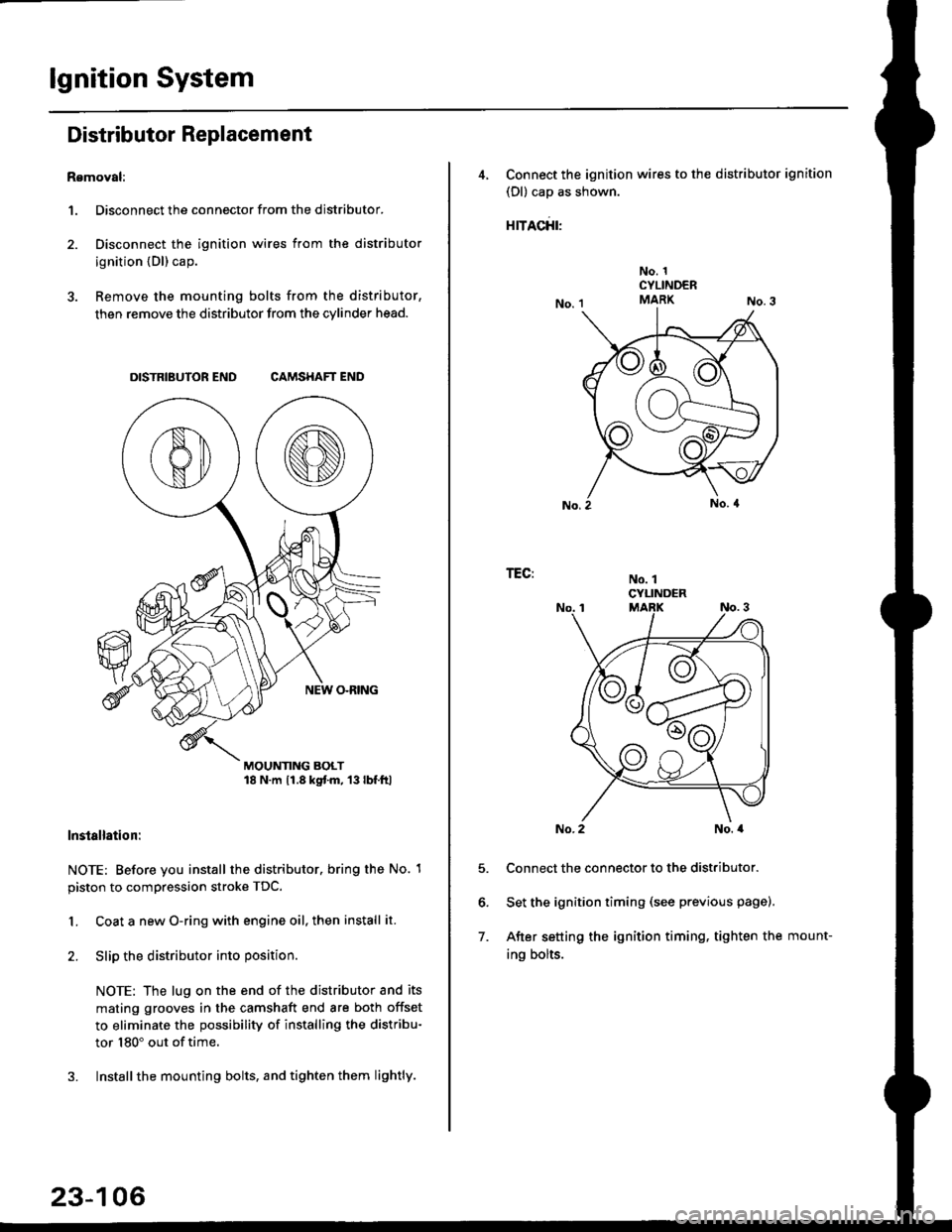
1. Disconnect the connector from the distributor.
2. Disconnect the ignition wires from the distributor
ignition {Dl) cap.
3. Remove the mounting bolts from the distributor,
then remove the distributor from the cylinder head.
DISTRIBUTOR END CAMSHAFT END
MOUNTING BOLT18 N.m 11.8 kgtm, 13lbf.ltl
lnstallation:
NOTE: Before you install the distributor. bring the No. 1
piston to compression stroke TDC.
1. Coat a new O-ring with engine oil, then install it.
2. Slip the distributor into position
NOTE: The lug on the end of the distributor and its
mating grooves in the camshaft end are both offset
to eliminate the possibility of installing the distribu-
tor 180" out of time.
3. Installthe mounting bolts, and tighten them lightly.
23-106
4, Connect the ignition wires to the distributor ignition
(Dl) cap as shown.
rracfit'
No. 1CYLINDERMARK
No. 1CYLINDER
TEG:
5.
6.
7.
No. 2No. a
Connect the connector to the distributor.
Set the ignition timing (see previous page).
After setting the ignition timing, tighten the mount-
ing bolts.