1996 HONDA CIVIC Elect
[x] Cancel search: ElectPage 55 of 2189
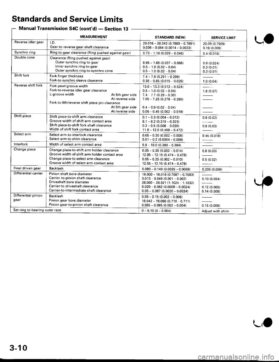
MEASUREMENTSTANDARD (NEW) SERVICE LIMITReverse idler geart.D.Gear-to reverse gear shaft clearance20.016 - 20.043 (0.7880 -0.7891)
0.036 - 0.084 {0.0014 - 0.0033)20.09 (0.7909)
0.16 (0.006)
Synchro ringRing to-gear clearance (Ring pushed against gear)0.73 - 1.18 (0.029 0.046)0.4 (0.016)Double coneClearance (Ring pushed against geadOuter synchro ring to gearIn ner synchro ring to-gearOuter synchro ring-to-synchro cone
0.9s - 1.68 10.037 - 0.066)0.5 - 1.0 (0.02 - 0.04)0.5 1.0 (0.02 - 0.04)
0.6 (0.024)
0.3 {0.01)0.3 (0.01)Shift forkFork {inger thicknessFork-to synchro sleeve clearance7.4 - 7.6 (0.291- 0.299i0.35 - 0.65 (0.015 0.026)1.0 (0.04)Beverse shift forkFork pawl groove widthFork-to-reverse idler gear clearanceL-groove width At 5th gear sideAt reverse sideFork'to-5th/reverse shift piece pin clearanceAt 5th gear sideAt reverse side
13.0 - 13.3 10.512 - 0.524)0.5 - 1.0 (0.02 - 0.04)7.4 t.1 10.29 -O.30)
7 .O5 - 7 .25 (0.21A - 0.2A5i'
0.4 0.9 (0.02 0.04)0.05 0.45 (0.002 - 0.018)
1€ {0.07)
Shift pieceShift piece-to-shift arm clearanceGroove width of shift arm contact areaShilt'piece-to-shift fork shaft clearanceWidth of shift lork contact area
0.1 - 0.3 (0.004 - 0.012)8.1-8.2 (0.319 - 0.323i0.2 - 0.5 (0.008 0.020)1 1.9 - 12.0 10.469 - 0.472)
0.6 (0.02)
0.8 (0.03)
Select armSelect arm-to-interlock clearanceSelect arm to-shim clearance0.05 - 0.20 (0.002 - 0.008)0.01 - 0.2 10.0004 - 0.008)0.45 (0.018)
InterlockWidth of select arm contact area9.9 - 10.0 (0.390 0.394)Change pieceChange piece-to-shilt arm holder clearanceGroove width ot shitt arm holder contact areaChange piece-to select arm clearanceGroove width of select arm contact area
0.05 - 0.35 (0.002 - 0.014)12.05 - 12.15 \0.474 -0.47a1
0.05 - 0.25 (0.002 - 0.010)12.05 - 12. t5 (0.474 - 0.478)
0.8 {0.03)
0.5 (0.02)
Final driven gearBacklash0.090 - 0.149 (0.0035 - 0.0059)0.200 (0.008)DifferentialcarrierPinion shatt bore diameterCarrier to-pinion shaft clearanceDriveshaft bore diameterCarrier-to driveshaft clearanceCarrier-to-int6rmediate shatt clearance
18.000 - 18.016 10.7087 - 0.7093)0.013 - 0.045 {0.001 0.002)24.000 - 28.021 11.1024 1.1032)0.020,0.062 (0.0008 - 0.0024)0.05 - 0.087 {0.0020 - 0.0034)
0.10 {0.004)
0.12 (0.005)
0.14 (0.006)
Differential piniongearBacklashPinion gear bore diameterPinion gear-to-pinion shaft clearance
0.05 -0.15 (0.002 - 0.006)18.042 18.066 (0.710 - 0.711)0.055 - 0.095 (0.002 - 0.004)0.15 (0.006)
Set ring to bearing outer race0 - 0.10 (0 - 0.004)Adjust with shim
Standards and
Manual Transmission
Service
S4C (cont'd)
Limits
- Section 13
ua
.'1'
3-10
L,O
Page 57 of 2189

Standards and Service Limits
Automatic Transmission (cont'd) - Section l4
MEASUREMENTSTANOARD {NEW)SERVICE LIMITDiameter of needle bearing contact areaOn mainshaft stator shaft bearingOn mainshaft 2nd gearOn mainshaft 4th gear collarOn mainshaft 1st gear collarOn countershaft (left side)On countershaft 3rd gear collarOn countershaft 4th gearOn countershaft reverse gear collarOn countershaft 1st gear collarOn reverse idler gear shaftInside diameter of needle bearing contact areaOn mainshaft 1st gearOn mainshaft 2nd gearOn mainshaft 4th gearOn countershaft 1st gearOn countershaft 3rd gearOn countershaft 4th gearOn countershaft reverse gearOn reverse idler gearOn stator shaft (ATF pump sideiOn stator shalt (stator side)Reverse idler gear shaft holder l.D.End playMainshaft lst gearMainshaft 2nd gearMainshaft 4th gearCountershaft lst gearCountershaft 3rd gearCountershaft 4th gearReverse idler gearCountershaft reverse gearSelecto. hub O.D.Mainshaft 4th gear collar lengthMarnshaft 4th gear collar Ilange thicknessMainshaft lst gear collar length
22.980 22.993 10.9047 0.9052|j35.975 35.991 (1.4163 - 1.4169)31.975 31.991 (1.2589_,1.2595)30.975 - 30.991 t1.2195 1.2201136.004 36.017 (1.4175 - 1.4180)35.980 35.996 (1.4165 - 1.4172)27.980 - 27.993 (1.1016 - 1.1021)31.975 31.991 (1.2589 - 1.2595)31.97s 31.991 (1.2589 - 1.2595)13.990 - 14.000 {0.5508 - 0.5512)
35.000,3s.016 (1.3780 - 1.3786)41.000 - 41.016 11.6142 - 1.6148)38.000 - 38.0'16 {1.4961 - 1.4967)38.000 38.016 (1.4961 - 1.4967)41.000 41.016 (1.6142 - 1.6148)33.000 - 33.016 (1.2992 1.2998)38.000 - 38.016 (1.4961 - 1.4967)18.007 - 18.020 (0.7089 - 0.7094)29.OO0 -29.O1311.1417 - 1.1422127.O00 27.02111.0630 - 1.0638)'14.416 - 14.434 (0.5676 0.5683)
0.08 0.19 (0.003 - 0.007)0.05 - 0.13 (0.002 0.005)0.075 - 0.185 (0.003 0.007)0.1 - 0.5 {0.004 - 0.020)0.05 - 0.17 {0.002 - 0.007)0.10 - 0.18 (0.004 0.007)0.05 - 0.18 (0.002 0.007)0.10 - 0.25 (0.004 0.010)51.87 - 51.90 {2.042 2.043)45.00 - 45.03 (1.771 - 1.773)4.435 - 4.525 (0.1746 - 0.1781)27.00- 27.15 (1.063 - 1.069)Countershaft distance collar length38.87 - 38.90 {1.530 - 1.531)38.92 38.95 {1.532 - 1.533)38.97 - 39.00 (1.534,1.535i39.02 - 39.05 (1.536 - 1.537)39.07 - 39.10 {1.538 - 1.539)39.r2 - 39.15 (1.540 - 1.541)39.17 - 39.20 (1.542 - 1.543)39.22 - 39.25 (1.544 - '�t.545)
39.27 39.30 (1.546 - 1.547)Countershaft 3rd gear collar length ,96 97 models'98 - 00 modetsCountershaft reverse gear collar lengthCountershaft reverse gear collar flangethacknessCountershaft 1st gear collar lengthCountershaft lst gear collar flange thickness
21.15 - 21.20 (0.833 - 0.835)20.65 20.70 (0.813 - 0.825)14.5 r4.6 {0.571 - 0.575)
2.4 - 2.6 10.094 0.102)14.s - 14.6 (0.571 - 0.575)2.4 2.6 (0.094 - 0.102)
Wear or damage
t a.\
L
Page 64 of 2189
ElectricalSection 23
*: When using a new belt, adjust deflection or tension to new values. Run the engine for 5 minutes then turn it off
Readiust deflection or tension to used belt values
Unit of englh: mm {n)
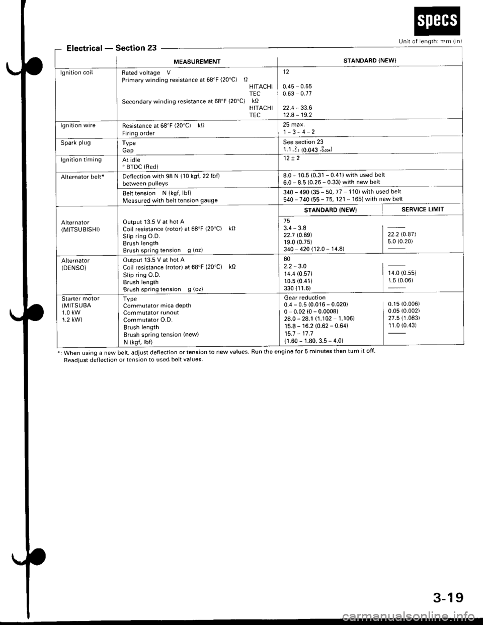
MEASUREMENTSTANDARD {NEW}
lgnition coilRated voltage VPrimary winding resistance at 68'F (20'C) oHITACHITEC
Secondary winding resastance at 68'F 120"C) kOHITACHITEC
12
0.45 0.550.63 0.11
22.4 - 33.612.A - 19.2
lgnition wireResistance at 68'F (20'C) kf)
Firing order
25 max.1-3-4 2
Spark plugTypeGap
See section 231.1 3, (o.o€ -3*.)
lgnition timingAt idle' BTDC lRed)
Alternator belt+Deflection with 98 N (10 kgf,22lbf)between pulleys8.0 - 10.5 {0.31 - 0.41} with used belt
6.0 - 8.5 {0.26- 0.33)with new belt
Belt tension N (kgf, lbf)
Measured with belt tension gauge340 - 490 (35 - 50, 77 110) with used belt
540 - 740 (55 - 75, 121. 165)whh newbert
(MITSUBISHI)Output l3.5 V at hot ACoal resistance (rotor) at 68'F (20"C) kO
Slip rins O.D.Brush lengthBrush spring tension g (oz)
STANDARD INEWI SERVICE LIMIT
753.4-3.8 I -
Z2.j \0.A9) 22.2 \0.47)19.0 (0.75) 5.0 (0.20)
340 420 (12.0 14.8)
Alternator(DENSOiOutput '13.5 V at hot A
Coil resistance (rotor) at 68'F (20'C) k0
Slip ring O.D.Erush lengthBrush spring tension g (oz)
802.2 - 3.014.4 (0.57) | 14.0 (0.55)
10.5 (0.41) 1.5 (0.06)
330 {11.6)
Starter(MITSUEA
1.0 kw1.2 kW)
TvpeCommutator mica depthCommutator runoutCommutator O.D.Brush lengthBrush spring tension (new)
N (ksf, lbf)
Gear reduction0.4 - 0.5 (0.016 - 0.020) 0.15(0.006)
o o.o2 (o - 0.000e) | o.o5 (o.oo2)
28.0-28.1 (1.102 1.106) | 27.5(1.083)
15.8 - 16.2 10.62 - 0.64) 11.0 (0.43)
15.7 - 11 .1
{1.60 - 1.80, 3.5 - 4.0i
3-19
Page 67 of 2189
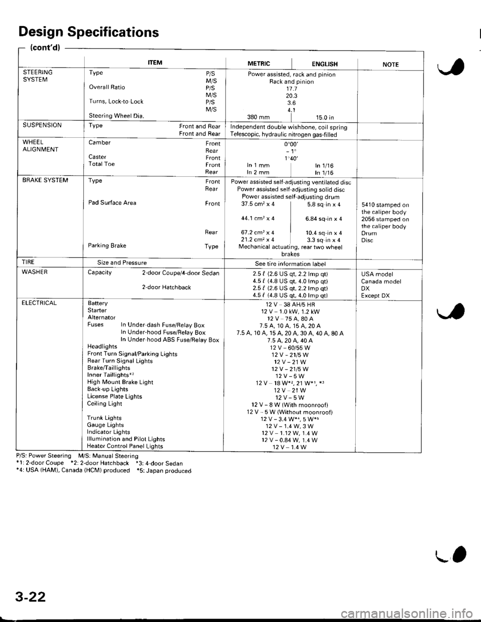
ITEMMETRICENGLISHNOTESTEERINGSYSTEMTvpe P/sM/SOverall Ratio p/S
M/STurns, Lock-to Lock p/S
M/SSteering Wheel Dia.
Power assisted, rack and pinionRack and pinion1l.120.33.64..1380 mm 15.0 inSUSPENSIONTYPe Front and RearFront and RearIndependent double wishbone, coil springTelescopic, hydraulic nitrogen gas-filled
WHEELALIGN| 4ENTCamber FrontRearCaster F.ontTotalToe FrontRear
0.00,- 't'
1.40'ln 1 mm ln 1/16In 2 mm In 1/16EBAKE SYSTEMType FrontRea r
Pad Surface Area Front
Rea r
Parking Brake Type
Power assisted self adjusting ventilated discPower assisted self adiustjng solid discPower assisted sell adjusting dr!m37.5 cm'�x 4 5.8 sq in x 4
44.1ctn,x4 ] 6.84sq-inxa
67.2 cmz x 4 | to.+ sq in ' I21.2 cm, x 4 3.3 sq in x 4Mechanical actuating, rear two wheelbrakes
5410 stamped onthe caliper body2056 stamped onthe caliper bodyDrumDisc
TIRESize and PressureSee lire intormation label
WASHERCapacity 2door Coupe/4,door Sedan
2,door Hatchback
2.5 f (2.6 LJS qt, 2.2 lmp qt)4.5 | (4.8 US qt,4.0lmp qt)2.51 (2.6 US qt, 2.2 lmp qt)4.5 f (4.8 US qt, 4.0 lmp qt)
USA modelCanada modelDXExcept DXELECTRICALBafteryStarterAlternatorFuses In Under dash Fuse/Felay BoxIn Under-hood Fuse/Belay 8oxIn Under hood ABS FLrse/Relay BoxHeadlightsFront Turn Signal/Parking LightsRear Turn Signal LaghtsBrake/TaillightsInner Taillights*,High Mount Brake LightBack up LightsLicense Plate LightsCeiling Light
Trunk LightsGauge LightsIndicator Lightslllumination and Pilot LightsHeater Control Panel Lights
12 V 38 AH/5 HR12 V 1.0 kW, 1.2 kW12V 75 A,80 A7.5 A, t0 A, 15 A, 20 A7.5 A, 10 A, 15 A, 20 A, 30 A, 40 A, 80 A7.5 4.20 A, 40 A12V_60/55W12V -2115W
12V - 21W12V - 21/5W12V-5W12 V 18 W*" 21 W+" *3
12V 21W12v-5wl2V-8W(Withmoonroofl12 V - 5W (Without moonroof)
12V-1.4W,3W't2 v 1.12W. 1.4 W12v-0.84w, 1.4 W12V 1.4 W
Design Specifications
(cont'd)
P/S: Power Steering M/S: Manual Steering*l: 2-door Coupe *2: 2door Hatchback *3: 4-door Sedan*4: USA (HAM), Canada (HCM) produced *5: Japan produced
3-22
L'
Page 105 of 2189

39. Remove the left and right front mount and bracket'
MOUNT/BRACKET
40. Remove the rear mount bracket.
41. Remove the uPPsr bracket.
42. Remove the transmission mount bracket, then
remove the transmission mount.
44.
Check that the engine/transmission is completely
free of vacuum hoses, fuel and coolant hoses and
electricalwiring.
Slowly raise the engine approximately 150 mm (6 in)'
Check once again that all hoses and wires are discon-
nected from the engine^ransmission
Raise the engine all the way, and remove it from the
car.
UPPER
TRANSMISSION
45.
5-11
Page 125 of 2189
Valve Seals
Replacement (Cylinder head removal not requiredl
NOTE: Cylinder head removal is not required in thisprocedure.
The procedure shown below applies when using the in-
car valve spring compressor (Snap-on YA884S withY48845 - 2 A7/8" attachment).
!@@ Alway wear approved eye protection whenusing ihe in-cai valve spring compressor.
1. Turn the crankshaft so that the No. I and the No. 4pistons are at top dead center (TDC).
2. Remove the cylinder head cover and the rocker arm
assembly.
NOTE:
. Refer to page 6-30 for rocker arm assembly
removat.
. When removing or installing the rocker armassembly, do not remove the camshaft holder
bolts. The bolts will keep the holders, springs
and rocker arms on the shaft.
. Refer to page 6-46 when installing the cylinder
head cover.
Remove the fuel injectors and the wire harness.
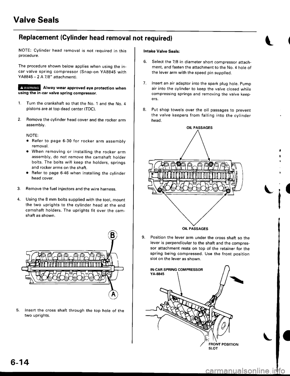
Using the 8 mm bolts supplied with the tool. mount
the two uprights to the cylinder head at the end
camshaft holders. The uprights fit over the cam-
shaft as shown.
lnsert the cross shaft through the top hole of thetwo uprights.
3.
4.
6-14
Intake Valve Seals:
6. Select the 7/8 in diameter short compressor attach-ment, and fasten the attachment to the No. 4 hole of
the leve. arm with the speed pin supplied.
8.
7.lnsert an air adapto. into the spark plug hole. pump
air into the cylinder to keep the valve closed whilecompressing springs and removing the valve keepers.
Put shop towels over the oil passages to prevent
the valve keepers from falling into the cylinder
neao.
OIL PASSAGES
Position the lever arm under the cross shaft so thelever is perpendicular to the shaft and the compres-
sor attachment rests on top of the retainer for thespring being compressed. Use the front position
slot on the lever as shown.
,
I
i'
OIL PASSAGES
IN-CAR SPRING COMPRESSOR
SLOT
Page 126 of 2189
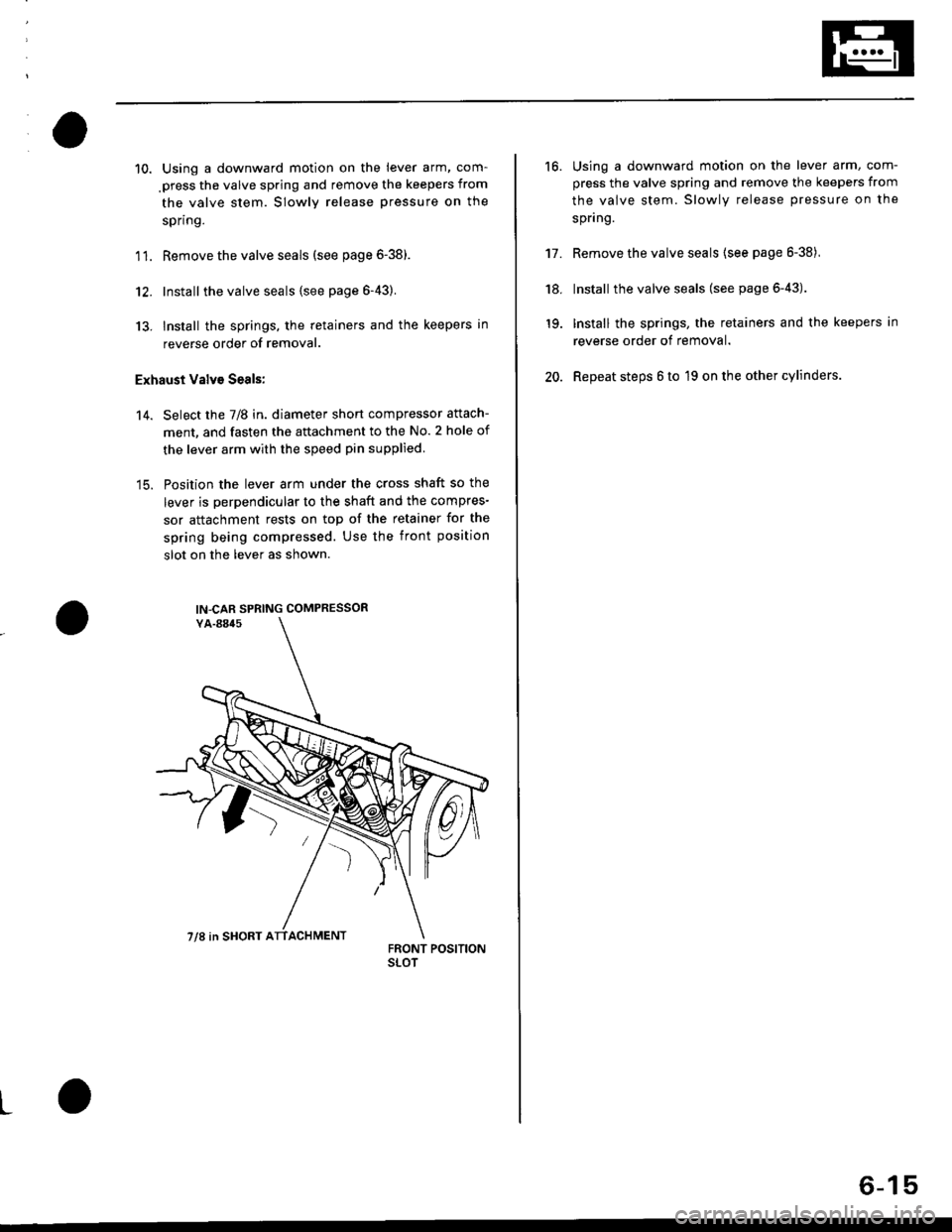
10. Using a downward motion on the lever arm, com-
.press the valve spring and remove the keepers from
the valve stem. Slowly release pressure on the
spring.
11. Remove the valve seals (see page 6-38).
12. Install the valve seals {see page 6-43).
13. Install the springs, the retainers and the keepers in
reverse order of removal.
Exhaust Valvs Sesls:
Select the 7/8 in. diameter short compressor attach-
ment, and fasten the attachment to the No. 2 hole of
the lever arm with the speed pin supplied.
Position the lever arm under the cross shaft so the
lever is perpendicular to the shaft and the compres-
sor attachment rests on top of the retainer for the
spring being compressed. Use the front position
slot on the lever as shown.
'14.
IN-CAR SPRING COMPRESSOR
7/8 in SHORT ATTACHMENT
L
16.Using a downward motion on the lever arm, com-
press the valve spring and remove the keepers from
the valve stem. Slowly release pressure on the
spnng.
Remove the valve seals {see page 6-38),
Install the valve seals (see page 6-43).
Install the springs, the retainers and the keepers in
reverse order of removal.
Repeat steps 6 to 19 on the other cylinders.
't7.
'18.
19.
20.
6-15
Page 152 of 2189

Valve Guides
7.
VALVESEAT
PFUSSIAN BTUE COMPOUNO
The actual valve seating surface. as shown by the
blue comDound, should be centered on the seat.
. lf it is too high (closer to the valve stem), you
must make a second cut with the 60'cutter to
move it down, then one more cut with the 45'
cutter to restore seat width,
. lf it is too low (closer to the vslve edge), you
must make a second cut with the 30" cutter to
move it uD, then one more cut with the 45'cutter
to restore seat width.
NOTE: The final cut should always be made with
the 45" cutter.
lnsert the intake and exhaust valves in the head and
measure the valve stem installed height.
Intake. Exhau3t Siem Installsd Height:
Standard (New): 53.17 - 53.6,4 mm
12.093 - 2.112 in)
Sorvice Limit: 53.89 mm (2.122 in)
lf the valve stem installed height is over the service
limit. reDlace the valve and recheck. lf its still over
the service limit, replace the cylinder head; the
valve seat in the head is too deep.
VALVE STEMINSTALLED HEIGHT
8.
\-
Replacement
1.As illustrated below, use a commercially-available
air-impact valve guide driver attachment modified
to fit the diameter of the valve guides. In most cases.
the same procedure can be done using the special
tool and a conventional hammer.
VALVE GUIDE DRIVERlCommerciallv available)5.3 mm
87 mm +- 57 mft
t3.43 in) | 12 24 inl
tr-r'10.8 mm(0.42 inl
or
VALVE GUIDE DRIVER, 5.5 mm
07742 - 0010100
Select the proper replacement guides. and chill them
in the freezer section of a refrigerator for about an
nour.
Use a hot plate or oven to evenly heat the cylinder
head to 300"F (150'C). Monitor the temperature with
a cooking thermometer.
CAUTION:
. Do not use a torch; it may warp the head.
Do not got the head hottel than 300"F (150"C1;
excessive heat may loosen thg valve seats.
To avoid burns. use heayy gloves whon handling
the heated cylinder h€ad.
{cont'd)
6-41