1996 HONDA CIVIC Door light
[x] Cancel search: Door lightPage 1274 of 2189
Ouarter Glass
Installation (cont'd)
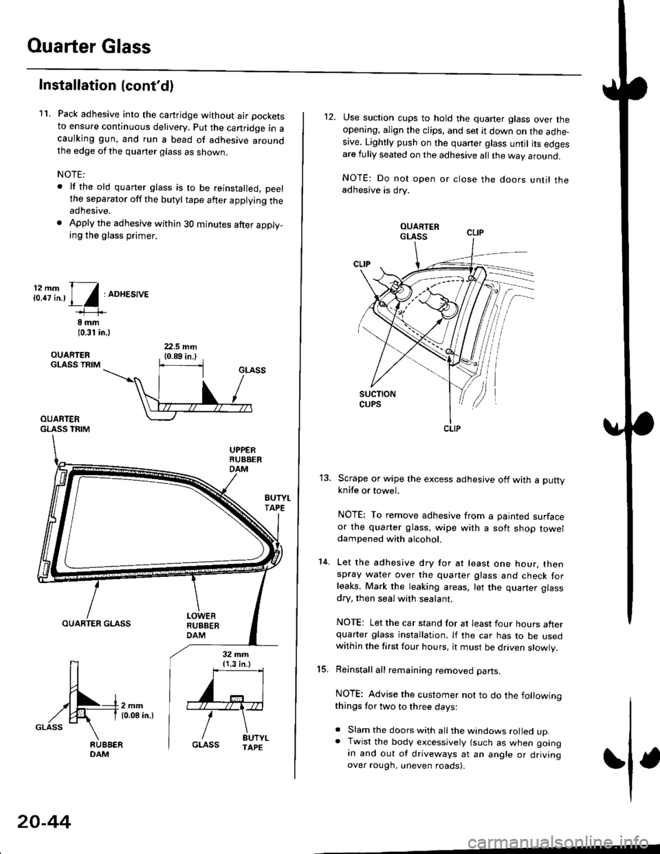
11. Pack adhesive into the cartridge without air pockets
to ensure continuous delivery. put the canridge in acaulking gun, and run a bead of adhesive aroundthe edge of the quarter glass as shown.
NOTE:
. lf the old quarter glass is to be reinstalled, peelthe separator off the butyl tape after applying theadhesive.
. Apply the adhesive within 30 minutes after apply_ing the glass primer.
i:.8i".,1/:ADHES,'E
8 rnm(0.31 in.l
OUARIERGLASS TRIM
OUARTERGLASS TFIM
BUTYI.TAPE
OUARTER GLASS
[-4m,^,GLASS \
32 mm{1.3 in.)
''='I
'"r"\
/ drt".GLASS TAPE
20-44
12. Use suction cups to hold the quarter glass over theopening, align the clips, and set it down on the adhe-sive. Lightly push on the quaner glass until its edgesare fully seated on the adhesive all the way around.
NOTE: Do not open or close the doors until theadhesive is drv.
Scrape or wipe the excess adhesive off with a puttyknife or towel.
NOTE: To remove adhesive from a painted surfaceor the quarter glass, wipe with a soft shop toweldampened with alcohol.
Let the adhesive dry for at least one hour, thenspray water over the quarter glass and check forleaks. Mark the leaking areas, let the quarter glass
dry, then seal with sealant.
NOTE: Let the car stand for at least four hours afterquarter glass installation. lf the car has to be usedwithin the first four hours, it must be driven slowly.
Reinstall all remaining removed parts.
NOTE: Advise the customer not to do the followingthings for two to three days:
. Slam the doors with all the windows rolled up.. Twist the body excessively (such as when goingan and out of driveways at an angle or drivingover rough, uneven roads).
15.
14.
CLIP
Page 1279 of 2189
}
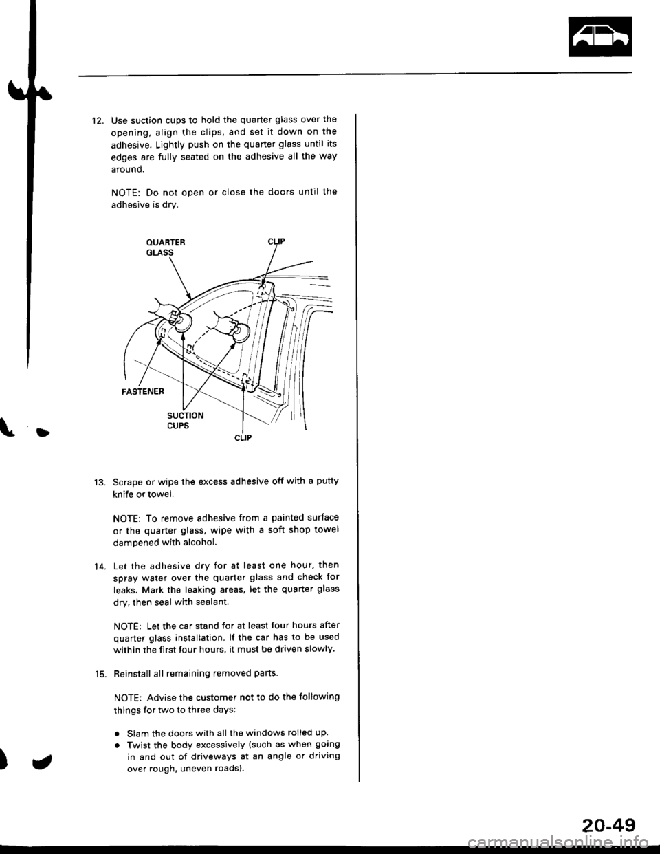
12. Use suction cups to hold the quarter glass over the
opening, align the clips, and set it down on the
adhesive. Lightly push on the quarter glass until its
edges are fully seated on the adhesive all the way
around.
NOTE: Do not open or close the doo.s until the
adhesive is dry.
Scrape or wipe the excess adhesive off with a putty
knife or towel,
NOTE: To remove adhesive from a painted surface
or the quaner glass, wipe with a soft shop towel
dampened with alcohol.
Let the adhesive dry for at least one hour, then
spray water over the quarter glass and check for
leaks. Mark the leaking areas, let the quarter glass
dry, then seal with sealant.
NOTE: Let the car stand for at least four hours after
quarter glass installation. lf the car has to be used
within the first four hours, it must be driven slowly
Reinstall all remaining removed parts-
NOTE: Advise the customer not to do the following
things for two to three days:
. Slam the doors with all the windows rolled up.
. Twist the body excessively (such as when going
in and out of driveways at an angle or driving
over rough, uneven roadsl.
13.
14.
)
CLIP
a
20-49
Page 1334 of 2189
Door and Side Moldings
Replacement (cont'dl
Door molding removal:
The following materials and tools are required to repairthe door moldings.
NOTE: Followthe manufacturer's instructions.
Materials: (Reference)
. Stripe remover
3M 08907
Stripe adhesive remover
3M 08908
Adhesive tape
3M Super Automotive Attachment Tape
Tools;
a Protective tape
. Knife or Cutter
. Sponge or Shop towel. Infrared dryer
. Film
. Putty knife
. Alcohol
CAUTION: Put on gloves to protect your hands,
Remove the door panel, and pull back the plastic
cover,
Apply protective tape on and around the molding.
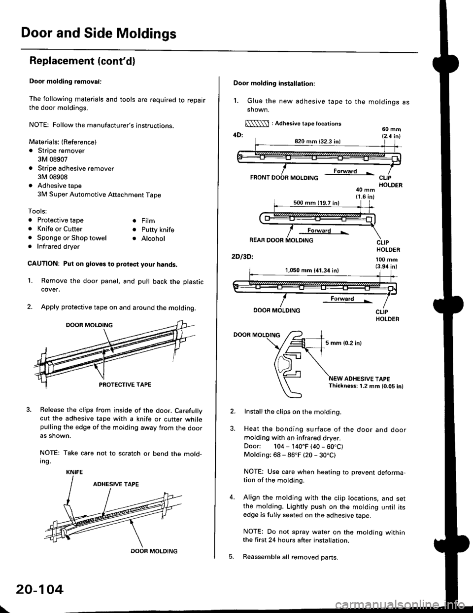
3. Release the clips from inside of the door. Carefullvcut the adhesive tape with a knife or cutter whilepulling the edge of the molding away trom the dooras shown.
NOTE: Take care not to scratch or bend the mold-Ing.
1.
KNIFE
DOOR MOLDING
\
20-104
Door molding installation:
1. Glue the new adhesive tape to the moldings assnown.
[\\\l : Adhesive tape tocations60 mm4D: t2 t i^l
40 mm11.6 in)
Forward L
REAR DOOR
2Dl3Dl
CLIPHOLDER
100 mm(3.94 inl1,050 mm 141.34 inl
Forward !
DOOR MOLDING
DOOR MOLDING
5 mm {0.2 inl
ADHESIVE TAPEThickness: 1.2 mm 10.05 in)
Installthe clips on the molding.
Heat the bonding surface of the door and doormolding with an infrared dryer.
Door: 104 - 140"F (40 - 60.C)Molding: 68 - 86"F (20 - 30.C)
NOTE: Use care when heating to prevent deforma-tion of the molding.
Align the molding with the clip locations, and setthe molding. Lightly push on the molding until itsedge is fully seated on the adhesive tape.
NOTE: Do not spray water on the motding withinthe first 24 hours after installation.
Reassemble all removed pans.
Page 1394 of 2189
Troubleshooting -'99 - 00 Models
Self-diagnosis Function
The heater control panel has a self-diagnosis function.
Running the Self-diagnosis Funqtion
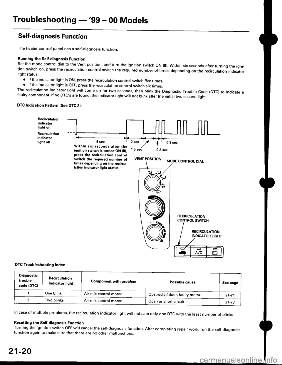
Set the mode control dial to the Vent position, and turn the ignition switch ON fll). Within six seconds after turnang the igni_tion switch on. press the recirculation control switch the required number of times depending on the recirculation indicatorlight status:
.lftheindicatorlightisON,presstherecirculationcontrolswitchfivetrmes.
.lftheindicatorlightisOFF,presstherecirculationcontrol switch six rrmes.The recirculation indicator light will come on for two seconds. then blink the Diagnostic Trouble code {DTc} to indicate afaulty component. lf no DTc's are found, the indicator light will not blink after the initial two second liqht.
DTC Indication Pattern (S6e DTC 2l:
Recirculationindicato.light on
Recirculationindicatorlight off2 sec
,/1.5 soct
' 0,3 secWithin six seconds atter theignition switch is turned ON (lll,pross the recirculation controlswitch the required number ottimes depending on the rocircu-lation indicetor light status
0.3 sec
VENT POSITIONMODE CONTROL DIAL
RECIRCULATIONCONTROL SWTCH
DTC Troubleshooting Index
Diagnostic
trouble
code (DTCI
Rgcirculation
indicator lightComponent with problemPossible causeSee page
One blinkAir mix control motorObstructed door, laulty motor21-21
2Two blinksAir mix control motorOpen or short circuit21-23
ln case of multiple problems, the recirculation indicator light will indicate only one DTc with the least number of blinks.
Resetting the Self-diagnosis FunctionTurning the ignition switch OFF will cancel the self-diagnosis function, After completing repair work, run the setf diagnosisfunction again to make sure that there are no other malfunctions.
21-20
@
At
V'
Page 1395 of 2189
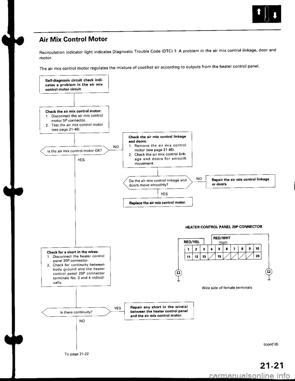
Air Mix Gontrol Motor
Recirculation indicator light indicates Diagnostic Trouble code (DTC) 1l A problem in the air mix control linkage, door and
motor.
The air mix control motor regulates the mixture of cool/hot air according to outputs from the heater control panel'
Self-diagnosis circuit check indi'
cates a Problem in the air mix
conlrol motor circuit,
Check th6 aii mix conirol motor:
1. Disconnect the air mix control
motor 5P connector.
2. Test the air mix control motor(see page 21-46).
check the air mix control linkage
and doors:1. Remove the air mix control
motor (see Page 21-46)
2. Check the air mix control link-
age and doors lor smooth
movement.
ls the air mix control motor OK?
Do the air mix control linkage and
doors move smoolhlY?
R€olace the air mix control motor'
Check tor a short in the wiles:
1. Disconnect the heater controlpanel 20P connector-2. Check for continuitY between
body ground and the heater
control panel 20P connector
terminals No.3 and 4 individ'
uaIY.
Ropair any short in th€ wire{s}
betweon the heater control Paneland the air mix control motor'
HEATER CONTROL PANEL 2OP CONNECTOR
RED/WHTRED/YEL
Wire side ot female terminals
(cont'd)
fo page 21-22
21-21
Page 1448 of 2189
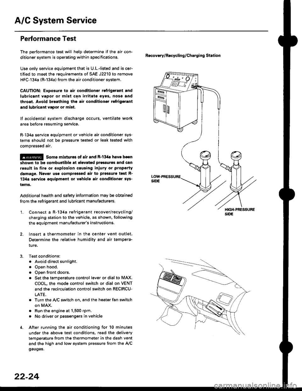
A/C System Service
Performance Test
The performance test will help determine if the air con-
ditioner system is operating within specifications.
Use only service equipment that is U.L.-listed and is cer-
tified to meet the reouirements of SAE J2210 to remove
HFC-134a (R-134a) from the air conditioner system.
CAUTION: Exposure to air conditionor rofrigerant and
lubricant vapor or mist can irrilalo €yes, nose and
throat. Avoid breathing tho air conditioner rstrigerrnt
and lubricant vapor or mist,
lf accidental system discharge occurs, ventilate work
area before resuming service.
R-134a service equipment or vehicle air conditioner sys-
tems should not be pressure tested or leak tested with
compressed air.
@ some mixtur$ of air and R-134a have been
shown lo b9 combustible rt glgvatad pr€ssur63 and can
resull in tire 01 oxplosion causing inlury ot property
damage. Never uao compre33ed air to pressure t99t R-
134a ssrvico 6quipmsnt or vohicla air conditioner sys-
tems.
Additional health and safety information may be obtained
from the refrigerant and lubricant manufacturers.
'1. Connect a R-134a refrigerant recover/recycling/
charging station to the vehicle, as shown, following
the equipment manufacturer's instructions.
2. lnsert a thermometer in the center vent outlet.
Determine the relative humidity and air tempera-
ture,
Test conditions:
. Avoid direct sunlight.
. Open hood.
. Open front doors.
. Set the temDerature control lever or dial to MAX,
COOL, the mode control switch or dial on VENT
and the recirculation control switch on RECIRCU-
LATE.
. Turn the A,/C switch on. and the heater fan switch
on MAX.
. Run the engine at 1,500 rpm.
. No driver or passengers in vehicle
After running the air conditioning for 10 minutes
under the above test conditions, read the delivery
temperature from the thermometer in the dash vent
and the high and low system pressure from the A,/C
gauges.
Recovery/Rocycling/Charging Station
22-24
Page 1471 of 2189

l'f .
Electrical
Special Toofs .,....................,23-2
Troubleshooting
Tips and Precautions ..............,.................... . 23-3
Five-step Troubleshooting .............. ......... . . 23-5
wire color codes ..........,23-5
Schematic Symbols ........,................... . . .. .... 23-6
Relay and Control Unit Locations
Engine Compartment ...,..................... ... .. . 23'7
Dashboard ......................23-8
Dashboard/Door ......... 23-12*Airbags ................. ....... Section 24
Air Conditioning ......... Section 21
Aftelnator ..........."""" """ 23-112
Anti-lock Brake System {ABS) Section 19*A/T Gear Position Indicator .....................,. .... ... 23-149
Automatic Transmission Svstem .... . ....... Section 14
Batterv ......... . . . ... ...... .......23-91
Blower controls .. . ... Section 2l
Charging System ....'...........23'112
Connector ldentilication and Wire Harness
Routing .................. ......23'13
Cruise Control ............,........23-240
Dash Lights Brightness Controller ............. ....... 23-180
Fan controfs "" 23'126
Fuel PumD ........ . ........ section 11
Fuses/Refay ...............,..,,.. 23'62
PGM-FI Control System ......................,....... Section 1 1
*Gauges
Circuit Diagram ....,.,.......23-131
Fuef Gauge ...........'.'.......23-142
Gauge/lndicator .. . .. 23-129
Ground Distribution .. . 23-75
Heatei controls .. . ..... Section 21*Horn................. ...............23-196
*tgnition Switch ....................23-89
lgnition System .......,.... 23-102
*lntegrated Control Unit ....................................... 23-156
fnterlock System ,........ . . , ,23-144
Lighting System . . . .. ......... 23-161
Lights, Exterior
Back-up Lights ..'............23'171
Brake Lights .................. 23'174
Daytime Bunning Lights (Canadal ............... 23'166
Front Parking Lights ......,................ .'. .......... 23-167
Front Turn Signal Lights .......... . . ............ ..,.23-167
Headtights ....".'....-... ..... 23'167
High Mount Brake Light ...................... ... .23'179
License Plate Lights ...... 23'176
Taitfights ................ .......23'171
lnterior Lights ..-.......,, . 23-142
Moonroof ..,.................,........ 23-235
Power Distribution ....... . . .23-61
Power Door Locks .......,,,. .23'251
Power Mirrors ,..............,.,...23'206
Power Relays ....... . ...... . . .. 23-86
Power Windows ............,,....23-220
Rear Window Defogger .......................... . . ... . . 23-2OO
Spark Plugs . ..... . ........ .....23-111
Slarting System ................23-93*stereo Sound Svstem ,................. ..... ... . ... ,.,.,,23'147'Supplemental Restraint System (SRS) ... . Section 24
Turn Signal/Hazard Flasher System .......'.'....-... 23-173
*Undel-dash Fuse/Relay Box ............,.................. 23-85
vehicfe soeed sensor (VSSI """" ""' 23-140+Wipers/Washers .........,.,.,...23-214
NOTE: Unless otherwise specified, references to auto-
matic transmission (Mf) in this section include the CVT.
Page 1506 of 2189
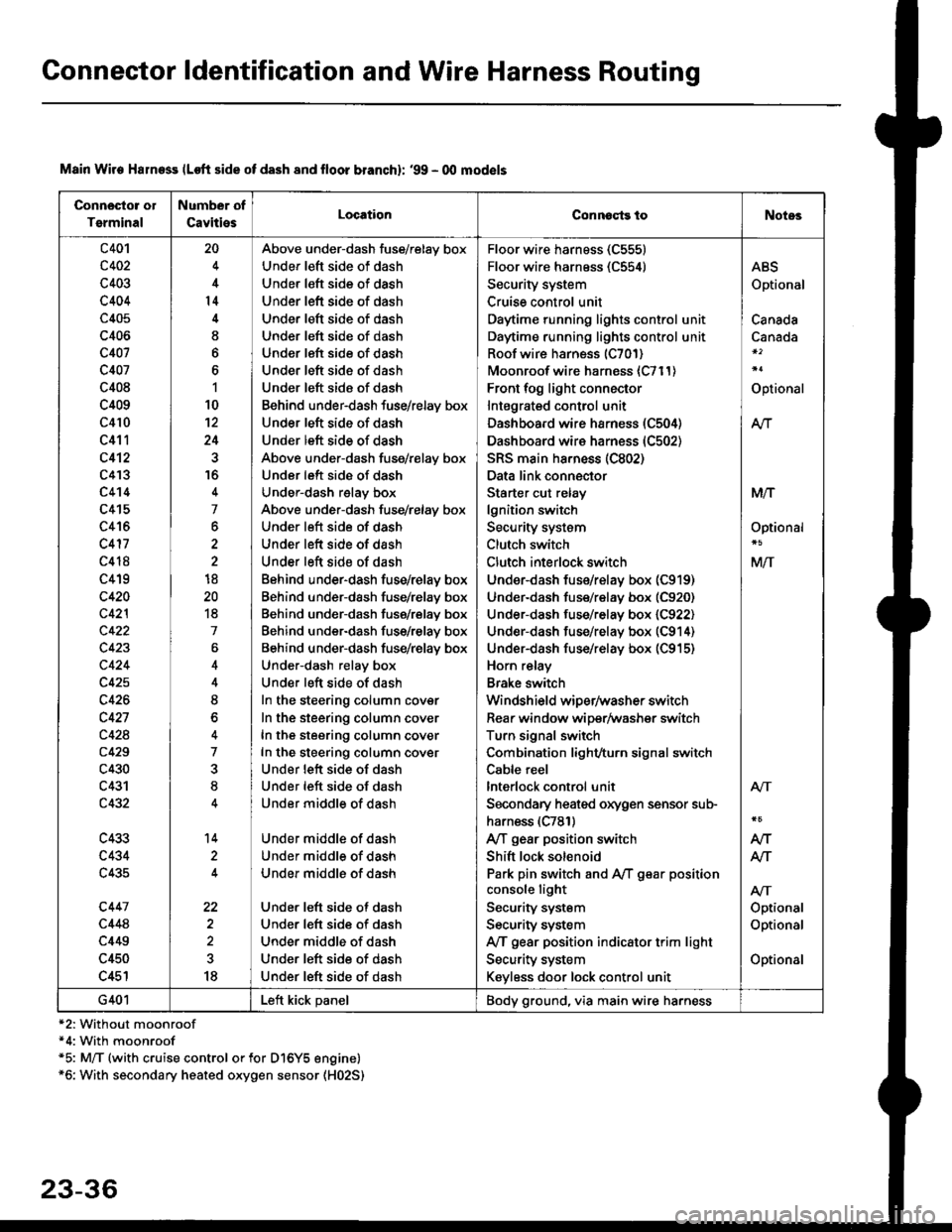
Connector ldentification and Wire Harness Routing
Connosto! ol
Tsrminal
Number of
CavitiesLocationConnoqtg toNotes
c401
c402
c403
c404
c405
c406
c407
c407
c408
c409
c410
c411
c412
c4'�I3
c4't4
c415
c416
c417
c418
c419
c420
c42l
c422
c423
c424
c425
c426
c427
c428
c429
c430
c431
c432
c433
c434
c435
c447
c448
c449
c450
c451
20
4
14
I
6
1
10
12
24
16
4
7
6
2
18
20
18
7
4
8
o
7
8
14
22
18
Above under-dash fuse/relay box
Under left side of dash
Under left side of dash
Under left side of dash
Under left side of dash
Under left side of dash
Under left side of dash
Under left side of dash
Under left side of dash
Behind under-dash fuse/relay box
Under left side of dash
Under left side of dash
Above under-dash fuse/relay box
Under left side of dash
Under-dash relay box
Above under-dash fuse/relay box
Under left side of dash
Under left side of dash
Under left side of dash
Behind under-dash fuse/relay box
Behind under-dash fuse/relay box
Behind under-dash fuse/relay box
Behind under-dash fuse/relay box
Behind under-dash fuse/relay box
Under-dash relay box
Under left side of dash
In the steering column cover
In the steering column cover
In the steering column cover
In the steering column cover
Under lett side of dash
Under left side of dash
Under middle of dash
Under middle of dash
Under middle of dash
Under middle of dash
Under left side of dash
Under left side of dash
Under middle of dash
Under left side of dash
Under left side of dash
Floor wire harness (C555)
Floor wire harness (C554)
Security system
Cruise control unit
Daytime running lights control unit
Daytime running lights control unit
Roof wire harness (C701)
Moonroof wire harness {C711)
Front fog light connector
Intagrated control unit
Dashboard wire harness (C504)
Dashboard wire harness (C502)
SRS main ha.ness (C802)
Data link connector
Starter cut relay
lgnition switch
Security system
Clutch switch
Clutch interlock switch
Under-dash fus€/relay box (C919)
Under-dash fuse/relay box (C920)
Under-dash fuse/relay box (C922)
Under-dash fuse/relay box (C914)
Under-dash fuse/relay box (C915)
Horn relay
Brake switch
Windshield wiper/washer switch
Rear window wiper/Washer switch
Turn signal switch
Combination light/turn signal switch
Cable reel
lnterlock control unit
Secondary heaied oxygen sensor sub-
harness (C781)
A/T gear position switch
Shift lock solenoid
Park pin switch and A,/T g€ar position
console light
Security system
Security system
IVT gear position indicator trim light
Security system
Keyless door lock control unit
ABS
Optional
Canada
Canada
Optional
At-|.
M/T
Optional
M/T
Atr
Optional
Optional
Optional
Atr
AIT
AJ-|.
G401Left kick panelBody ground, via main wire harness
Main Wire Halness lLoft side of dash 8nd lloor branchl: '99 - 00 mod€ls
*2: Without moonroof*4: With moonroof*5: M/T (with cruise control or for Dl6Y5 engine)*6: With secondary heated oxygen sensor (H02S)
23-36