1996 HONDA CIVIC Cam shaft seal
[x] Cancel search: Cam shaft sealPage 159 of 2189

Gylinder Head/Valve Train
816A2 engine
Special Tools ............. 6'50 Rocker Arms
VTEC Contlol System
Troubfeshooting Flowchart ............ 6-51 Disassembly/Reassembly ...............6'72
VTEC Solenoid ValveRocker Arms and Lost Motion Assemblies
Inspection ...""'...... 5-54 Inspection .........""' 6-73
VTEC Rocker ArmsRocker Arms and Shafts
Manual Inspection ........................... 6-54 Clearance Inspection ..'..."'.............. 6-74
Inspection Using Special Tools .....' 6-55 Camshafts
Valve Clearance
.^ Adiustment .........." 6-57 Valves'Valve Springs and Valve Seals
. t Crankshaft Pulley and Pulley Bolt Removal """"""""' 6-77
Replacement ..".....6-59 Valve Seats
Timing BeltReconditioning ......6'78
Cylinder Headlnstallation '............ 6-82
Page 175 of 2189
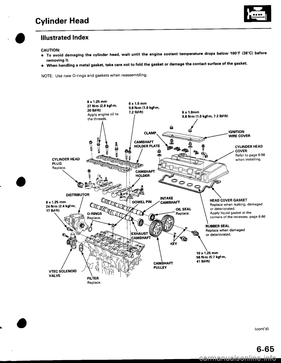
Cylinder Head
lllustrated Index
CAUTION:
. To avoid damaging the cylinder head, wait until the engine coolant tempsraturo drops below 100"F (38"C1 bofote
removing it,
. when handling a metal gasket, take caro not to fold the gaskot or damage the contact surface of the gasket.
NOTE: Use new O-rings and gaskets when reassembling.
CYLINDER HEAO
PLUGReplace.
)@
DISTRIBUTOR
8 x 1 ,25 mm
27 N.m P.E kgl m.
20 tbf.foApply engine oil to
the threads.
cr.rMp.S
CAMSHAFT A"o''*t*'; wes@
OIL SEALReplace.
6 x l,omm9.8 N'm tl.0 kgt'm,7.2lbf ft)
RUBBER SEALReplace when damaged
or detedorated.
6x1.0mm9.8 N.m (1.0 kgf'm,
7.2 rbnftl
fi%
IGNMONWIRE COVER
CYLINOER HEAD
COVERRefer to page 6-86
when installing
HEAD COVER GASKETReplace when leaking, damaged
or deteriorated.Apply liquid gasket at thecorners of the recesses, Page 6-86
8 x 1,25 mm24 N.m {2.4 kgf'm,
1? tbf.ftl
EXHAUST
10 x 1.25 mm56 N.m (5.7 kgf m,,r1 lbl.ft)
(cont'd)
6-65
Page 195 of 2189
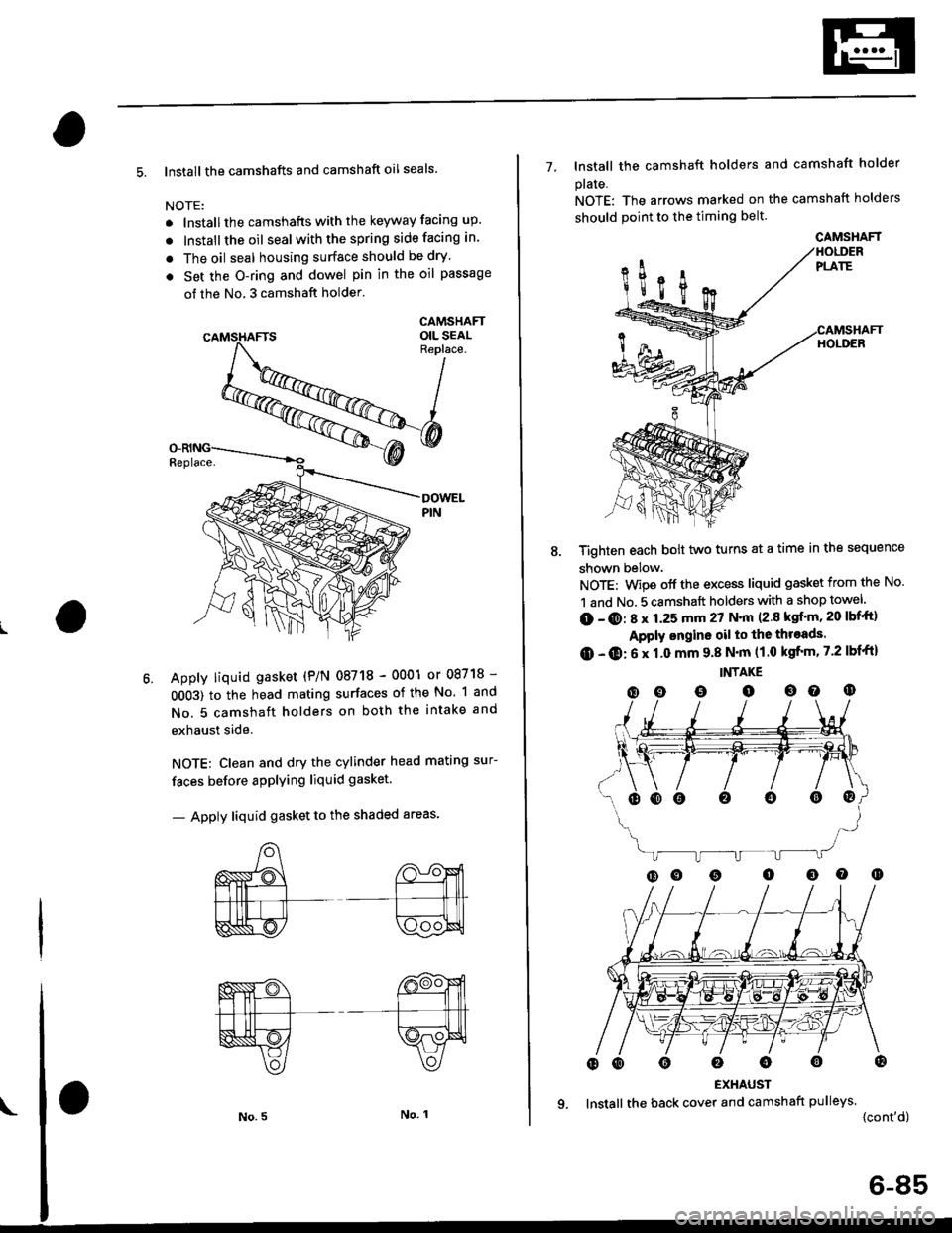
5. lnstall the camshafts and camshaft oil seals.
NOTE:
. lnstallthe camshafts with the keyway facing up.
. lnstall the oil seal withthespring side facing in.
. The oil seal housing surface should be dry'
. Set the O-ring and dowel pin in the oil passage
of the No, 3 camshaft holder'
CAMSHAFTOIL SEALReplace.
Apply liquid gasket (P/N 08718 - 0001 or 08718 -
0OO3) to the head mating surfaces of the No. 1 and
No. 5 camshaft holders on both the intake and
exhaust side.
NOTE: Clean and dry the cylinder head mating sur-
faces before applying liquid gasket.
- Apply liquid gasket to the shaded areas'
7- lnstall the camshaft holders and camshaft holder
plaIe.
NOTE: The arrows marked on the camshaft holders
should point to the timing belt.
Tighten each bolt two turns at a time in the sequence
shown below.
NOTE: Wipe off the excess liquid gasket from the No.
1 and No. 5 camshaft holders with a shop towel
(D - @: 8 x 1.25 mm 27 N.|n (2.8 ksf'm, 20 lbf'ft)
Apply ongine oil to the throads.
O - O: 6 x 1.0 mm 9.8 N'm (1.0 kgfrm, 7.2 lbf'ft)
INTAKE
(D o o o oo o
EXHAUST
lnstall the back cover and camshaft pulleys.
{cont'd)
oooo0o@
CAMSHAFT
6-85
Page 591 of 2189
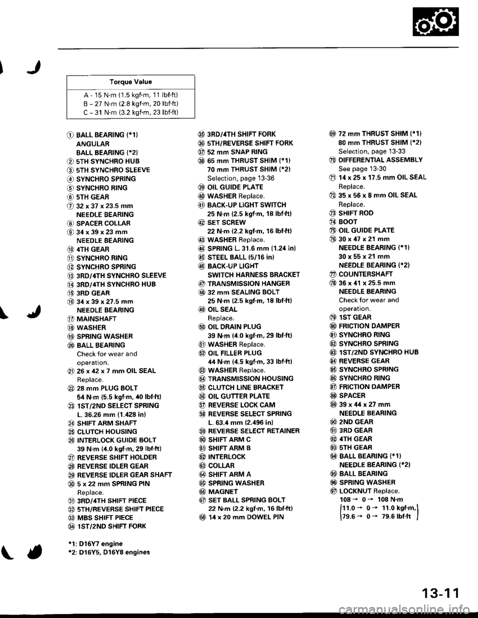
Torque Value
A - 15 N.m (1.5 kgf.m, 1'1 lbf.ft)
B - 27 N.m (2.8 kgf.m. 20 lbift)
C - 31 N.m {3.2 kgnm, 23 lbift)
\
O BALL BEARING (*T)
ANGULAR
BALL BEARING {*2I
O 5TH SYNCHRO HUB
O 5TH SYNCHRO SLEEVE
€) SYNCHRO SPRING
o SYNCHRO B|NG
@ 5TH GEAR
@ gz xgt x 23.5 mm
NEEDLE BEARING
@ SPACER COLLAR
@34x39x23mm
NEEDLE BEARING
(D 4TH GEAR
O SYNCHRO RING
C) SYNCHRO SPRING
CO 3RD/4TH SYNCHRO SLEEVE
@ 3RD/4TH SYNCHRO HUB
(} 3RD GEAR
@34x39x27.5mmNEEDLE BEARING
G) MAINSHAFT
G) WASHER
@ SPRING WASHER
@ BALL BEARING
Check for wear and
operation.(E 26x42x7 mm OIL SEAL
Replace.
@ 28 mm PLUG BOLT
5,1 N.m {5.5 kgf'm, /t0 lbt'ft)
@ lsT/zND SELECT SPRING
L. 36.26 mm (1./P8 in)
@ SHIFT ARM SHAFT
@ CLUTCH HOUSING
@ INTEELOCK GUIDE BOLT
39 N.m (4.0 kgf.m, 29 lbf.ftl
@ REVERSE SHIFT HOLDER
@ REVERSE IDLER GEAR
@ REVERSE IDLER GEAR SHAFT
@ 5 x 22 mm SPRING PIN
Replace.
@ 3RD/4TH SHIFT PIECE
@ 5TH/REVERSE SHIFT PIECE
@ MBS SHIFT PIECE
@ 1ST/2ND SHIFI FORK
*1:D16Y7 engine*2: D16Y5, D16Y8 engines
@ 3RD//|TH SHIFT FORK
@ 5TH/REVERSE SHIFT FORK
@ 52 mm SNAP RING
@ 65 mm THRUST SHIM (*11
70 mm THRUST SHIM (*21
Selection, page 13-36
@ OIL GUIDE PLATE
@ wASHER Replace.
@ BACK.UP LIGHT SWITCH
25 N.m (2.5 kgf'm, 18 lbf'ft)
@ sET SCREW
22 N.m {2.2 kgf.m, 16 lbl.ft}
@ WASHER Replace.
@D SPRING 1.31.6 mm (1.2,1inl
@ STEEL BALL 15/16 in)
@ BACK-UP LIGHT
SWITCH HARNESS BRACKET
@ TRANSMISSION HANGER
@ 32 MM SEALING BOLT
25 N.m (2.5 kgf.m, 18 lbt'ft)
@ OIL SEAL
Replace.
@ OIL DRAIN PLUG
39 N.m (4.0 kgf.m, 29 lbf.ft)
@ WASHER Replace.
@} OIL FILLER PLUG
44 N.m (4.5 kgf.m, 33 lbf'ftl
@ WASHER Replace.
@) TRANSMISSION HOUSING
€) CLUTCH LINE BRACKET
@ OIL GUTTER PLATE
@ REVERSE LOCK CAM
@ REVEBSE SELECT SPRING
L. 63.4 mm {2.,196 in)
@ REVERSE SELECT RETAINER
@ SHIFT ARM C
@ SHIFT ARM B
@ INTERLoCK
@ COLLAR
@ SHIFT ARM A
@ SPRING WASHER
@ MAGNET
@ sET BALL SPRING BOLT
22 N.m (2.2 kgf.m, 16 lbf.ftl
@ 14 x 20 mm DOWEL PIN
@ 72 mm THRUST SHIM l*11
80 mm THRUST SHIM (*21
Selection, page '13-33
@ DIFFERENTIAL ASSEMBLY
See page 13-30
@ 14 x 25 x 17.5 mm OIL SEAL
Replace.
@ 35 x 56 x 8 mm OIL SEAL
Replace.
@ SHIFT ROD
@ BOOr
@ OIL GUIDE PLATE
@30x47x21 mm
NEEDLE BEARING (* 1}
30x55x21 mm
NEEDLE BEARING {'2)
@ COUNTERSHAFT
@36x41 x 25.5 mm
NEEDLE BEARING
Check for wear and
operatron.
@ lsT GEAR
@ FRICTION DAMPER
@ SYNCHRO RING
@ SYNCHRO SPRTNG
@ lST/2ND SYNCHRO HUB
@ REVERSE GEAR
@ SYNCHRO SPRING
@ SYNCHRO RING
@ FRICTION DAMPER
@ SPACER
@39x4lx27mm
NEEDLE BEARING
@ 2ND GEAR
@ 3RD GEAR
@ 4TH GEAR
@ sTH GEAR
@) BALL BEARING {* 1}
NEEDLE BEARING (*2}
@ BALL BEARING
@) SPRING WASHER
@ LoCKNUT Replace.
108 - 0- 108 N.m
ftt.o* o- 1r.o kst.m,l
179.6- 0- 79.6 rbtft I
13-1 1
Page 609 of 2189
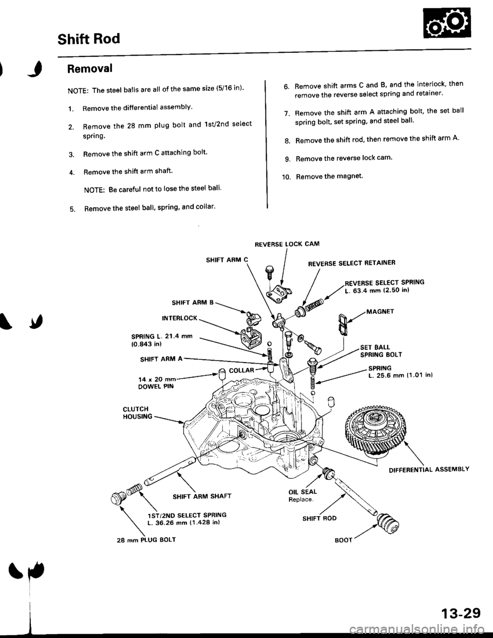
Shift Rod
Removal
NOTE: The steel batlsareall of the same size (5/16 in)'
1. Remove the differential assembly'
2. Remove the 28 mm plug bolt and lst/2nd select
spring.
3. Remove the shift arm C attaching bolt'
4. Remove the shift arm shaft'
NOTE: Be careful notto lose the steel ball'
5. Remove the steel ball, spring, and collar'
SHIFT ARM C
SHIFT ARM B
INTERLOCK
6. Remove shift arms C and B, and the interlock, then
remove the reverse select spring and retainer'
7. Remove the shift arm A attaching bolt, the set ball
spring bolt, set spring, and steel ball'
8. Remove the shift rod' then remove the shift arm A'
9. Remove the reverse lock cam'
10. Remove the magnet.
CAM
REVERSE SELECT RETAINER
REVERSE SELECT SPRING
L. 63.4 mm {2.50 inl
REVERSE LOCK
lIV/
' lJ
\s
SPRING L. 21.4 mm(0.843 in)
SI{IFT ARM A
14x20OOWEL PIN
COLLAR
,*(S* \
6S* srtrr ran,t srarr
\
',)r,r"o r..."r "rr,*n
t. 36.26 mm {1.428 in,
28 mm PI-UG BOLT
OIL SEALReplace.
&-"onn"
BALLSPRING EOLT
SPRINGL. 25.6 mm 11.01 inl
DIFFERENTIAL ASSEMBLY
SHIFT ROD
Page 619 of 2189

Transmission
Reassembly
NOTE: The steel balls are all ofthe same size (5/16 in).
1. Install the magnet and reverse lock cam.
2. Set shift arm A on the clutch housing, then install
the shift rod.
3. Install the spring washer and shift arm A attaching
bolt.
Installthe steel ball, spring, and set ball spring bolt.
Install shift arm B in the interlock, then set it on the
clutch housing.
1.
Insert shift arm shaft in the clutch housing.
Install the collar, spring. and steel ball into the case.
Compress the ball and insert the shift arm shaft,
Install shift arm C in shift arm A, then insert the shift
arm shaft.
Install the reverse select retainer and reverse select
spring onto shift arm shaft.
Install the differential assembly.
5.
8.
9.
10.
A:8x1.0mm3'l N,m (3.2 kgt.m,23 lbf.ft)
6 x 1.0 mm15 N.m 11.5 kgt.m, 11 lbt'ftl
OIL SEALReplace.
SI{IFT ARM C
COLLAR
REVERSE SELECT SPRINGL. 63.4 mm 12.50 in)
REVERSE LOCK CAM
REVERSE SELECT RETAINER
sHtFT ARM ' ___\.*^
rNrERLocK p
|Jiiill---=l@
MAGNET
SET BALL SPRING BOLT22 N.m 12.2 kgl.m, 16 lbf'ftl
SPRINGL. 25.6 mm (1.O1 in)
SHIFT AFM A
CLUTCHHOUSING
SHIFT ARM SHAFT
(cont'd)
13-39
SHIFT ROD
l
BOOT
Page 1098 of 2189
Power Steering Pump
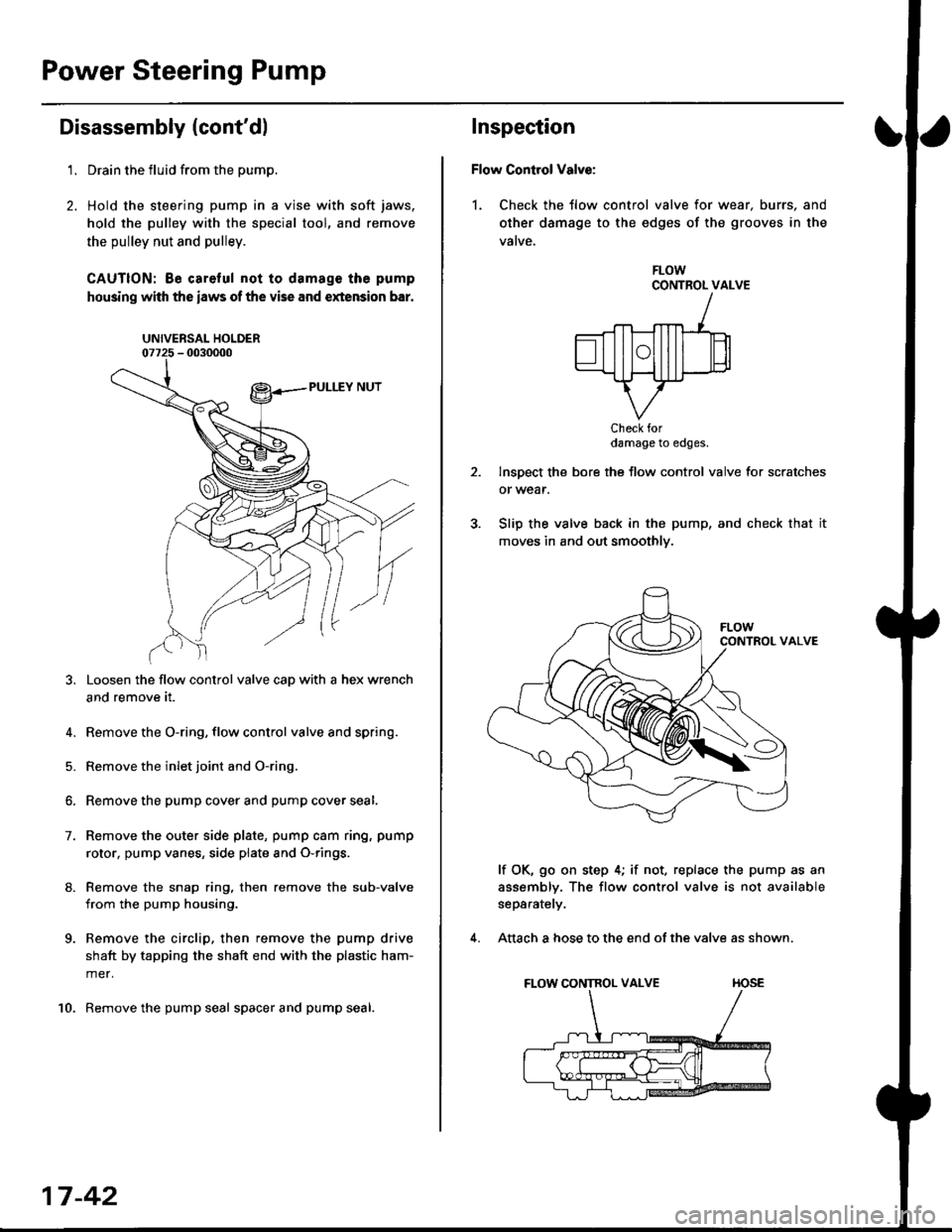
Disassembly (cont'dl
2.
't.Drain the fluid from the pump.
Hold the steering pump in a vise with soft jaws,
hold the pulley with the special tool, and remove
the pulley nut and pulley.
CAUTION: Be careful not to damage the pump
housing with the iaws of the vise and extension bar.
UNIVERSAL HOLDER
Loosen the flow control valve cap with a hex wrench
and remove it.
4. Remove the O-ring, flow control valve and spring.
5. Remove the inlet joint and O-ring.
6. Remove the pump cover and pump cover seal.
7. Remove the outer side plate, pump cam ring, pump
rotor, pump vanes, side plate and O-rings.
8. Remove the snap ring, then remove the sub-valve
from the pump housing.
9. Remove the circlip, then remove the pump drive
shaft by tapping the shaft end with the plastic ham-
mer.
10. Remove the pump seal spacer and pump seal.
17-42
Inspection
Flow Control Valve:
1. Check the tlow control valve for wear. burrs, and
other damage to the edges of the grooves in the
vatve,
FLOWCONTROL VALVE
Check fordamage to edges.
Inspect the bore the flow control valve for scratches
or wear.
Slip the valve back in the pump, and check that it
moves in and out smoothly.
lf OK, go on step 4; if not, replace the pump as an
assembly. The flow control valve is not available
separately.
Attach a hose to the end of the valve as shown.
FLOW CONTROL VALVE TIOSE
4.
Page 1100 of 2189
Power Steering Pump
Reassembly
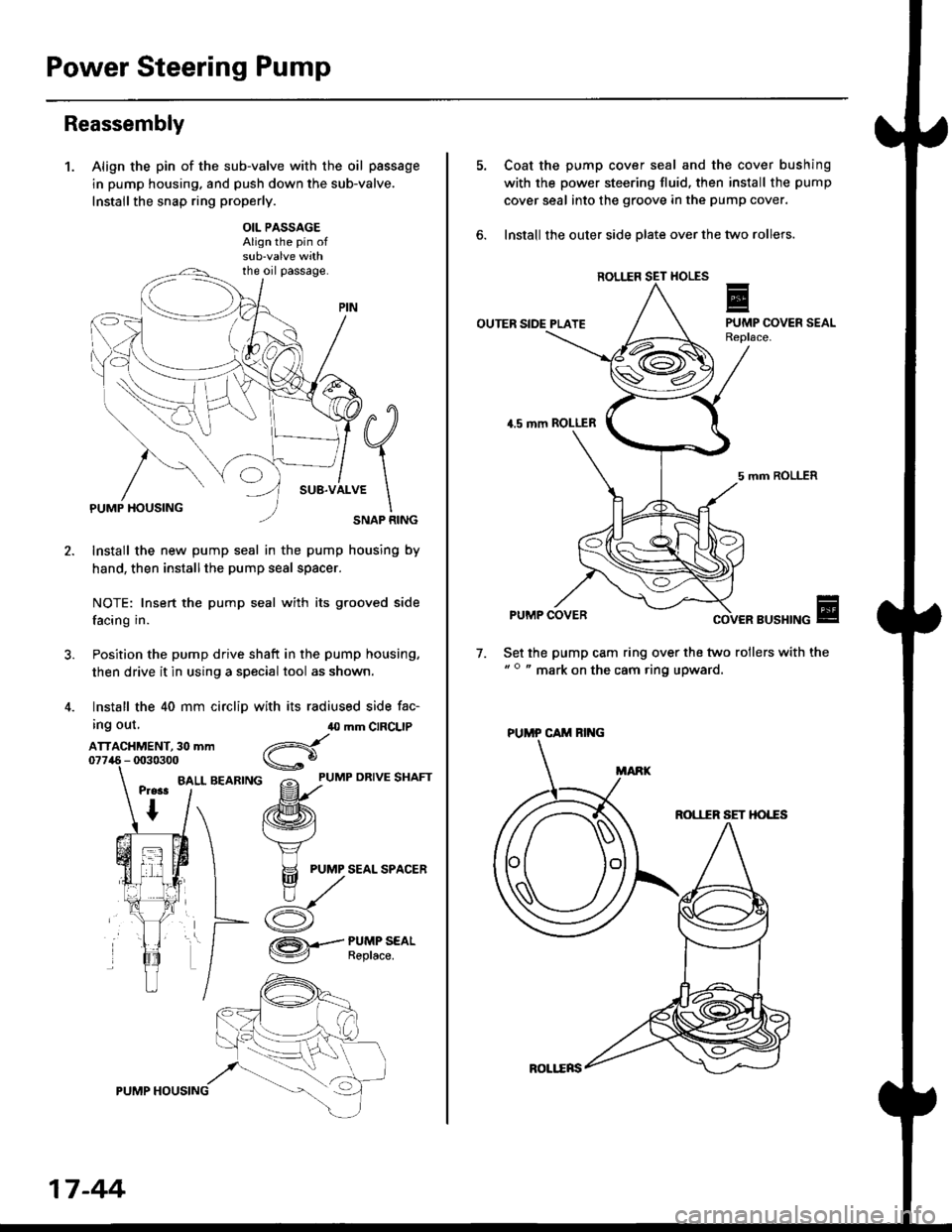
1.Align the pin of the sub-valve with the oil passage
in pump housing. and push down the sub-valve.
Installthe snap ring properly.
OIL PASSAGEAlign the pin of
the oil passage.
PUMP HOUSINGSNAP RING
Install the new pump seal in the pump housing by
hand, then installthe pump seal spacer.
NOTE: Insert the pump seal with its grooved side
facing in.
Position the pump drive shaft in the pump housing,
then drive it in using a special tool as shown.
Install the 40 mm circlip with its radiused side fac-
ing out,
ATTACHMENT, 30 mm
BALL BEARING
40 mm CIRCLIP
d
gf'uMP oRrvE sHAFr
/ffi\
f.\'vj
H PUMP SEAL SPACER
n,/
/:K
/ZA\.-- PUMP SEAL
V Reptace.
17 -44
ROLl.ERS
Coat the pump cover seal and the cover bushing
with the power steering fluid, then install the pump
cover seal into the groove in the pump cover.
lnstall the outer side olate over the two rollers.
ROL1IR
OUTER SIDE PLATE
4.5 mm ROLLER
5 mm ROLLER
PUMP COVERBUSHING
Set the pump cam ring over the two rollers with the" o " mark on the cam ring upward.
7.
ROI,IIR SET HO'"ES
PUMP CAM RING