1996 HONDA CIVIC engine wire
[x] Cancel search: engine wirePage 1135 of 2189
)
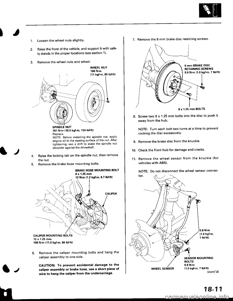
1.Loosen the wheel nuts slightlY.
Raise the front of the vehicle, and support it with safe-
ty stands in the proper locations (see section 1).
Remove the wheel nuts and wheel.3.
l)
WHEEL NUT'108 N.m
18'l N.m 118.5 kgf m, 134lblfti
Replace.NOTEI Before installing the spandle nut, apply
engine oil to the seating surface of the nut After
tightening, use a drift to stake the spindle nut
shoulder againsl the driveshaft
Raise the locking tab on the spindle nut, then remove
the nut.
Remove the brake hose mounting bolts.
BRAKE HOSE MOUNTING BOLT
I x 1.25 mm12 N.m (1,2 kgtm,8,7 lbf'ftl
6. Remove the caliper mounting bolts and hang the
caliper assembiy to one side
CAUTTON: To prevent accidental damage to the
caliper assembly or brake hoso' use a short piece of
wire to hang the caliPer tlom lhe undelcarriage.
{11 kgf m, 80 lbl.ft)
CALIPER MOUNTING BOLTS12 x 1.25 mm108 N.m {'11.0 kgtm, 80 lbt.ft)
7. Remove the 6 mm brake disc retaining screws.
8.
I x 1.25 mm BOLTS
Screw two 8 x 1.25 mm bolts into the disc to push it
away from the hub,
NOTE: Turn each bolt two turns at a tame to prevent
cocking the disc excessivelY.
Remove the brake disc from the knuckle.
Check the front hub for damage and cracks.
Remove the wheel sensor from the knuckle (for
vehicles with ABS).
NOTE: Do not disconnect the wheel sensor connec-
tor.
N.m
6 mm BRAKE OISCRETAINING SCREWS9.8 N.m t1.0 kgf.m, 7 lbf'ft)
{'1.0 kgf m,
7 tbf.ft)
10.
11.
MOUNTING
WHEEL
BOLTS9.8 N.m11.0 kgf,m, 7 lbf'ft)(cont'd)
Page 1215 of 2189
Troubleshooting
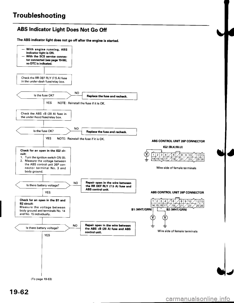
The ABS indicator light does not go off after the engine is started.
- With engine running, ABSindicator light is ON.- With tho SCS sewice connec-to. connected l3oe page 19-561,no DTC is indicated,
Checkthe RR DEF RLY {7.5 A)tusein the under-dash fuse/relay box.
Raphco tha furo and rochack.
Check the ABS +B (20 A) fuse inthe under hood tuse/relay box.
R6pl.ce tho tu3c lnd r.ch.ck.
Chock for an open in the lG2 cir-GUrt:1. Turn the ignition switch ON (lt).2. Measure the voltage betweenthe ABS control unh 26P con-nector terminal No. 3 andbody ground.
Bopair opcn in tha wir. botw.cnth. RR DEF RLY 17.5 Al tus. .ndABS control unit.
Check tor an opon in thG Bl end82 circuit:Measure the voltage betweenbody ground and terminals No. 14and No. 15 individually.
Rrpair opsn in tha wiro t atwa,anthe ABS +B (20 Al fu.r .nd ABScontrol unh.
ls there banery voltage?
1To page 19-63)
ABS Indicator Light Does Not Go Off
YES NOTE: Feinstattthe luse it it is OK.
YES NOTE: Reinsta
the fuse if it is OK.ABS CONTROL UNIT 26P CONNECTOR
IG2IELK/BLUI
Wire side of female terminals
ABS CONTBOL UN]T 26P CONNECTOR
8T IWHT/GRNI
Wire side of temale terminals
19-62
Page 1217 of 2189
Troubleshooting
Wheel Sensor
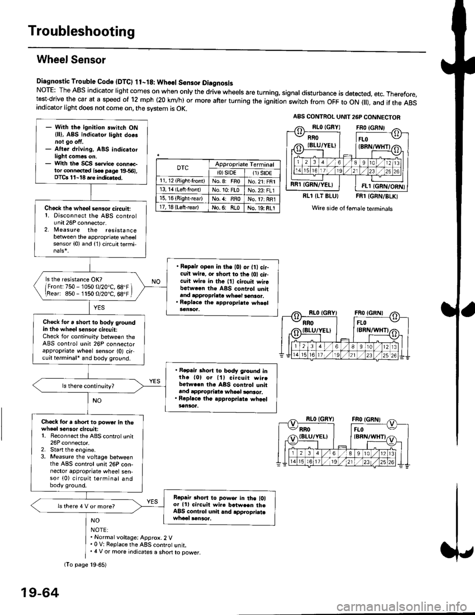
Diagnostic Trouble Gode {DTC) ll-18: Wheol S€n3ol DiagnosisNoTE: The ABS indicator light comes on when only the drive wheels are turning, signal disturbance is detected, etc. Therefore,test-drive the car at a speed of 12 mph (20 krn/h) or more after turning the ignition:witch from OFF to ON fll), and if the ABSindicator light does not come on, the svstem is OK.
0TcAppropriate Terminal(0)srDE11) SrD€r 1, 12 (Right-front)No.8: FRoNo.21: FRI13, 14 (Left-front)No. 10: FLoNo.23: FL115, 16 {Right-rear)No. {: RRoNo. 17: RRl17, 18 (Left-rear)No.6: RLoNo. 19: RLI
RLl (LT BLU}FRl (GRN/BLKI
Wire side ol female terminals
NO
NOTE:. Normal voltage: Approx.2 V' 0 V: Replace the ABS controt unit.. 4 V or more indicates a short to power.
A8S CONTROL UNIT 26P CONNECTOR
RRO
IBLU/YELI
RR1 IGRN/YELIFL1 IGRN/ORN}
- With the ignition switch ON{ll), ABS indicator tighr doe.noi go off,- Aftsr driving, ABS indicatotlight comes on.- With the SCS so.vice connac-tor conn€c,ted {soe pege 19-561,DTCs 11-18 a.e indicrted.
Chock lhe wheol sensor ci.cuit:1. Disconnect the ABS controlunit 26P connector.2. lleasure the resistancebetween the appropriate wheelsensor (0) and (1) circuit termi,
. Reprir op€n in the l0l or {0 cir-cuit wiro, or shon to thc {01 cir-cuit wi.o in thc {11 circuit wircbctween ths ABS control unitand approprieto wheel a6nsor.. R.pl.ce th€ epp.opri.te wheal3€nloa.
ls the resistance OK?
/Frontr 750 - 1050 o/20"C, 68.F \\Rear: 850- 1150 O/20.C, 68"F /
Check toru short to body groundin the wheel senso. circuit:Check for continuity between theABS control unit 26P connectorappropriate wheel sensor (0) circuit terminali and body ground.
. Rapair short to body ground inth6 (0) or lll cilcuit wi..bctwa.n th6 ABS control unitand appropdaie whoel lonsor.. Rep|'c6 tho appropriatc whcelsanlor.
Chock tor a sho.t to powe. in thowheel3en3or circuit:1. Reconnect the ABS control unit26P connector,2. Start the engine.3. Measure the voltage betweenthe ABS control unit 26P con-nector appropriate wheel sen-sor (0) circuit terminal andbody ground.
Ropair rhon to powo. in the l0lor lll circuit wire batw.en th€ABS cont.ol unit and .pplopriatawhccl !€naoa,
ls there 4 V or more?
fio page 19-65)
19-64
Page 1219 of 2189
Troubleshooting
Solenoid
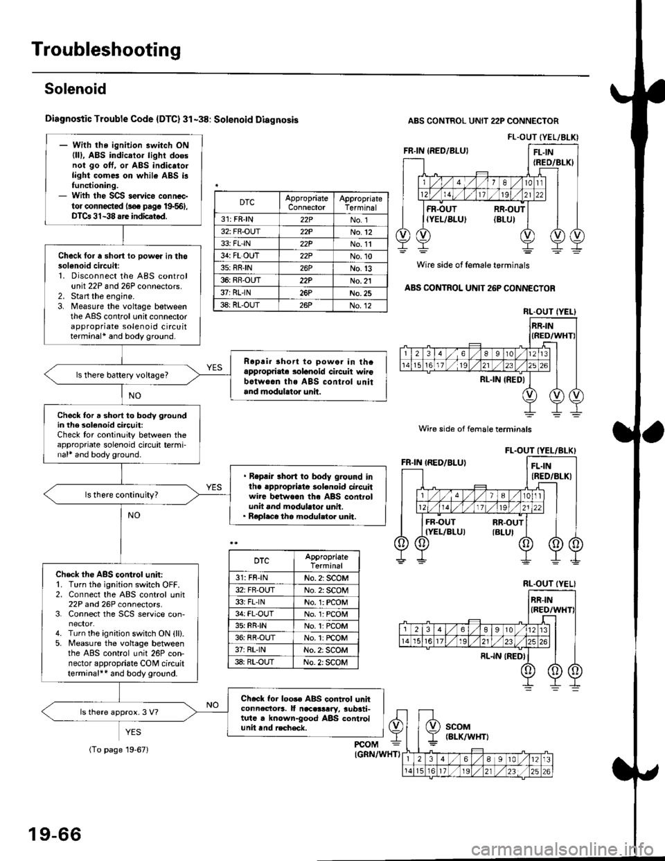
Diagnostic Trouble Code {DTC} 31-38: Solenoid Diagnosis
YES
ABS CONTROL UNIT 22P CONNECTOR
Wire side of female terminals
ABS CONTROL UNIT 26P CONNECTOR
FL.OUT (YEL/ALK)- With the ignition switch ON(lll, ABS indicator light doesnol go oft. or ABS indic.to.light comes on while ABS i3functioning.- With the SCS servico connec-tor connected ls€. pag€ 19-561,DTCa 31-38 are indicstod.
Check for a short lo powor in thosol6noid circuitl1. Disconnect the ABS controlunit 22P and 26P connectors.2. Sta rt the engine.3. Measure the voltage betweenthe ABS control unit connectorappropriate solenoid circuitterminal* and body ground.
Ropri. short to powor in thcappropriate solanoid ci.cuit wirobotw6.n ths ABS cont.ol unitand modulrtor unit.
ls there battery voltage?
Check for a short to body groundin the 3olenoid circuit:Check tor continuity between theappropriate solenoid circuit termi-nal* and body ground.
. Repair short to body ground inlhe .ppropriato solonoid circuitwire betwoan th6 ABS controlunit and modllato. unit.. Replaco the modul.tor unit.
Check th€ ABS control unit:'1. Turn the ignition switch OFF.2. Connect the ABS control unit22P and 26P connectors.3. Connect the SCS service con-
4. Turn the ignition switch ON {ll}.5. Measure the voltage betweenthe ABS control unit 26P con-nector appropriate CONI circuitterminal++ and body ground.
Check for loos€ ABS control unhconnectora. It naceslrry, aub3ti-tutc . known-good ABS controlunit tnd recheck.
ls there approx. 3 V?
DTCAppropriateConnectorAppropriateTerminal
31: FRJN22PNo. 1
32: FR-OUT22PNo.12
33i FL'IN22PNo. 11
34: FL OUT22PNo.10
3s: RRIN26PNo.13
36: RR-OUT22PNo. 21
37: RLIN26PNo.25
38: RL-OUT26PNo.12RL.OUT IYEL}
Wire side of female terminals
DTCAppropriateTerminal
31: FR-lNNo. 2: SCOM
32: FR-OUTNo. 2: SCOM
33i FLINNo. 1: rcOM
34: FL-OUTNo. l: PCOM
35: RR{NNo.1:PCOM
36: RR-OUTNo. 1: rcOM
37rRL'lNNo. 2: SCOM
38: RL-OUTNo. 2: SCOM
RL.OUT (YEL}
19-66
(To page 19-671
Page 1226 of 2189
![HONDA CIVIC 1996 6.G Workshop Manual lgnition Voltage
Diagnostic Trouble Code (DTC) 61: lgnhion Voltage Diagno3is
A8S CONTROL UNIT 26P CONNECTOR
IG2IBLK/BLU}
]Wire side of lemale terminals
- With tha engin€ running, ABSindicator lighl HONDA CIVIC 1996 6.G Workshop Manual lgnition Voltage
Diagnostic Trouble Code (DTC) 61: lgnhion Voltage Diagno3is
A8S CONTROL UNIT 26P CONNECTOR
IG2IBLK/BLU}
]Wire side of lemale terminals
- With tha engin€ running, ABSindicator lighl](/manual-img/13/6068/w960_6068-1225.png)
lgnition Voltage
Diagnostic Trouble Code (DTC) 61: lgnhion Voltage Diagno3is
A8S CONTROL UNIT 26P CONNECTOR
IG2IBLK/BLU}
]Wire side of lemale terminals
- With tha engin€ running, ABSindicator lighl is ON.- With the SCS s€rvice connec-to. conn€ctod ls€€ page 19-561,DTC 61 is indicated.
Problem v€rification:1. Erase the DTC.2. Start the engine.3. Make sure that the ABS ind;cator light comes on and DTC61 is indicated.
ls DTC 61 indicated?The system b OK .t this time.
Check the lG2 cilcuii:Measure the voltage between theABS control unit 26P connectorterminal No. 3 and body ground.
ls there 18 V or above?
lf the vohage is 0 V, check lor anopon in the lG2 circuit.It there is 12 - 17 V. substitute aknown-good ABS colrtrol unit andJecheck.
It
19-73
Page 1414 of 2189
Heater Unit
Replacement (cont'dl
6.
7.
8.
9.
Remove the dashboard (see section 20).
Remove the heater duct (see page 21-37) or evapo-
rator (see page 22-28).
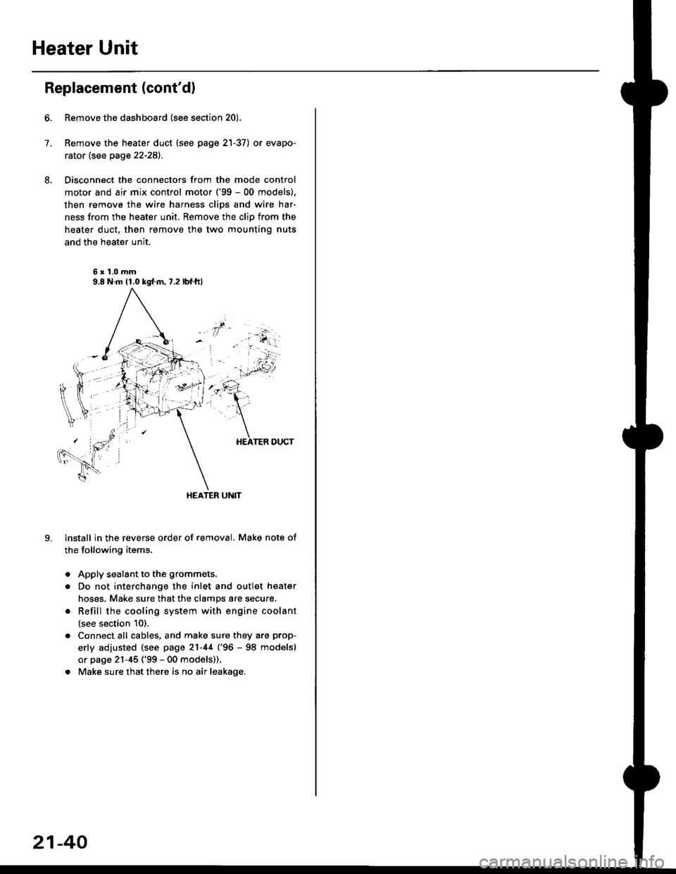
Disconnect the connectors from the mode control
motor and air mix control motor ('99 - 00 models),
then remove the wire harness clips and wire har-
ness from the heater unit. Remove the clip from the
heater duct, then remove the two mounting nuts
and the heater unit.
6x1.0mm9.8 N.m 11.0 kgl.m,7.2 lbf.ftl
HEATER UNIT
lnstall in the reverse order of removal. Make note of
the following items.
Apply sealant to the grommets.
Do not interchange the inlet and outlet heater
hoses. Make sure that the clamps are secure.
Refill the cooling system with engine coolant
(see section 10).
Connect all cables, and make sure they are prop-
erly adjusted (see page 21-44 (96 - 98 models)
or page 21-45 ('99 - 00 models)).
Make sure that there is no air leakage.
21-40
Page 1442 of 2189
Troubleshooting
A/C System (cont'd)
From page 22-11
. _Ff,, __
I11213[
,r,il*"-T",-.r-'..owrRE I
To page 22-19 1'96 - 98 models)
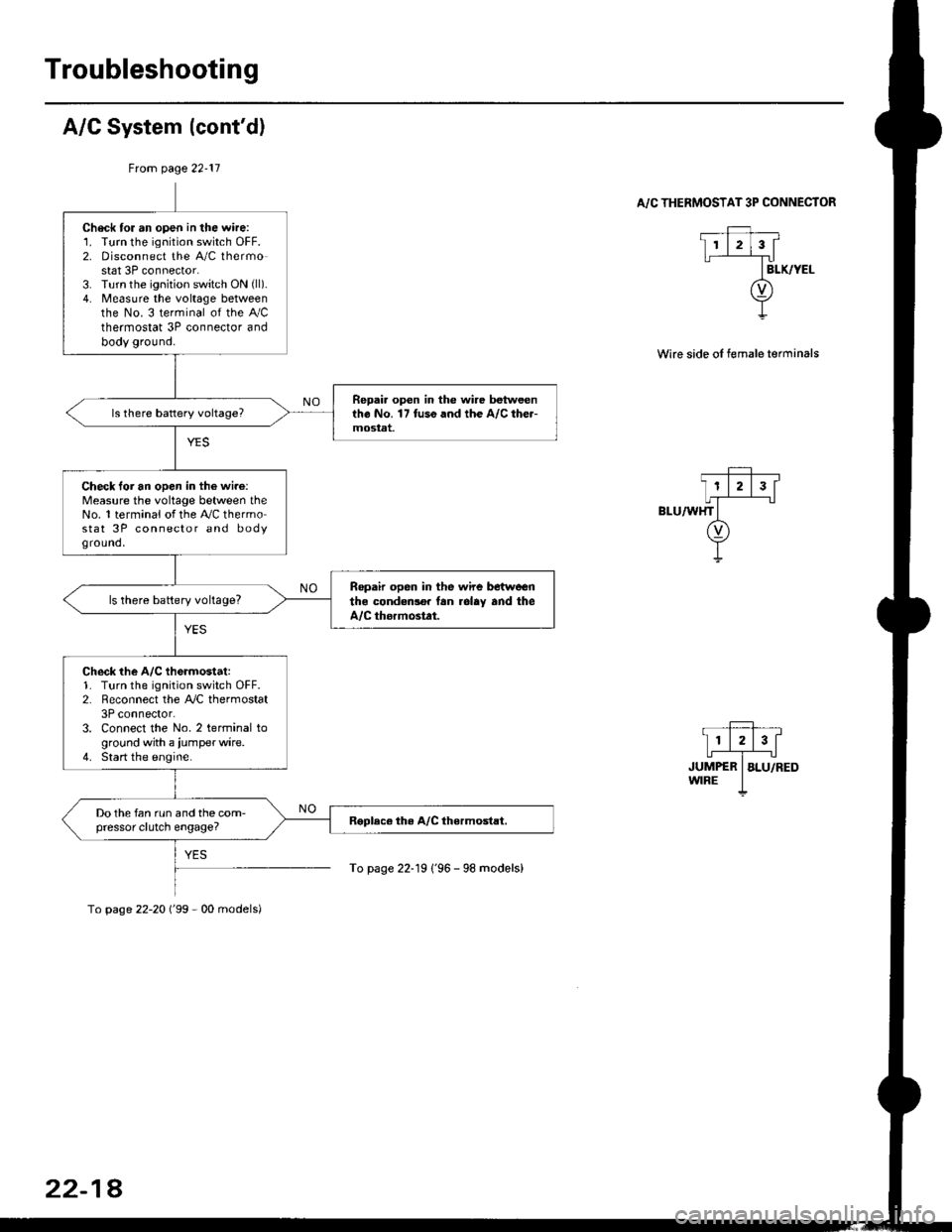
A/C THERMOSTAT 3P CONNECTOR
Wire side oI female terminals
Check tor an open in the wire:1. Turn the ignition switch OFF.2. Disconnect the A/C thermostat 3P connector.3. Turn the ignition switch ON (ll).
4. Measure the voltage betweenthe No. 3 terminal of the Ay'Cthermostat 3P connector andbody ground.
Repai. open in the wire betweentho No. 17 tuso and the A/C the.-mostat.
Check loi an open in the wi.e:Measure the voltage between theNo. 1 terminal of the A,/C thermostat 3P connector and bodyground,
Ropair open in the wire betwoenthe condedlo. lan rolay and theA/C thormostat.
ls there battery voltage?
Check the A/C th6rmostat:1. Turn the ignition switch OFF.2. Reconnect the A,/C thermostat3P connector.3. Connect the No. 2 terminal toground with a iumperwire.4. Start the engine.
Do the fan run and the com-pressor clutch engage?
To page 22-20 ('99 - 00 models)
22-18
Page 1471 of 2189

l'f .
Electrical
Special Toofs .,....................,23-2
Troubleshooting
Tips and Precautions ..............,.................... . 23-3
Five-step Troubleshooting .............. ......... . . 23-5
wire color codes ..........,23-5
Schematic Symbols ........,................... . . .. .... 23-6
Relay and Control Unit Locations
Engine Compartment ...,..................... ... .. . 23'7
Dashboard ......................23-8
Dashboard/Door ......... 23-12*Airbags ................. ....... Section 24
Air Conditioning ......... Section 21
Aftelnator ..........."""" """ 23-112
Anti-lock Brake System {ABS) Section 19*A/T Gear Position Indicator .....................,. .... ... 23-149
Automatic Transmission Svstem .... . ....... Section 14
Batterv ......... . . . ... ...... .......23-91
Blower controls .. . ... Section 2l
Charging System ....'...........23'112
Connector ldentilication and Wire Harness
Routing .................. ......23'13
Cruise Control ............,........23-240
Dash Lights Brightness Controller ............. ....... 23-180
Fan controfs "" 23'126
Fuel PumD ........ . ........ section 11
Fuses/Refay ...............,..,,.. 23'62
PGM-FI Control System ......................,....... Section 1 1
*Gauges
Circuit Diagram ....,.,.......23-131
Fuef Gauge ...........'.'.......23-142
Gauge/lndicator .. . .. 23-129
Ground Distribution .. . 23-75
Heatei controls .. . ..... Section 21*Horn................. ...............23-196
*tgnition Switch ....................23-89
lgnition System .......,.... 23-102
*lntegrated Control Unit ....................................... 23-156
fnterlock System ,........ . . , ,23-144
Lighting System . . . .. ......... 23-161
Lights, Exterior
Back-up Lights ..'............23'171
Brake Lights .................. 23'174
Daytime Bunning Lights (Canadal ............... 23'166
Front Parking Lights ......,................ .'. .......... 23-167
Front Turn Signal Lights .......... . . ............ ..,.23-167
Headtights ....".'....-... ..... 23'167
High Mount Brake Light ...................... ... .23'179
License Plate Lights ...... 23'176
Taitfights ................ .......23'171
lnterior Lights ..-.......,, . 23-142
Moonroof ..,.................,........ 23-235
Power Distribution ....... . . .23-61
Power Door Locks .......,,,. .23'251
Power Mirrors ,..............,.,...23'206
Power Relays ....... . ...... . . .. 23-86
Power Windows ............,,....23-220
Rear Window Defogger .......................... . . ... . . 23-2OO
Spark Plugs . ..... . ........ .....23-111
Slarting System ................23-93*stereo Sound Svstem ,................. ..... ... . ... ,.,.,,23'147'Supplemental Restraint System (SRS) ... . Section 24
Turn Signal/Hazard Flasher System .......'.'....-... 23-173
*Undel-dash Fuse/Relay Box ............,.................. 23-85
vehicfe soeed sensor (VSSI """" ""' 23-140+Wipers/Washers .........,.,.,...23-214
NOTE: Unless otherwise specified, references to auto-
matic transmission (Mf) in this section include the CVT.