1996 HONDA CIVIC control unit
[x] Cancel search: control unitPage 1971 of 2189
How the Circuit Works
Seat Belt Warning
With the ignition switch in ON (ll) or START (lll),
battery voltage is applied to the seat belt reminder
light. When the seat belt is not buckled, the seat
belt reminder/key-on beeper circuit in the
integrated control unit senses ground through the
closed seat belt switch. The seat belt reminder light
comes on and stays on, and the beeper beeps for
6 seconds. The reminder light and beeper will stop
when the seat belt is buckled or the timer circuit
deactivates them.
lgnition Key Warning
Battery voltage is supplied at all times to the seat
belt reminder/key-on beeper circuit in the
integrated control unit. When you turn on the
ignition key switch the integrated control unit
senses ground. lf you open the driver's door, the
door switch closes, causing the beeper to sound
until the door is closed.
Refer to the Service Manual (Section 23, Electrical)
for specitic tests or troubleshootrng procedures.
73-1
Page 1972 of 2189
![HONDA CIVIC 1996 6.G Workshop Manual Low Fuel Indicator Light
l
t
I
I
I
IJ
pag6 106.
,
-ls,T,*-*:lligff*,
l,;l:l?,
A3A
!-{ilril}-1 PowERTRAtNI Lowtuel I CONTROL
I i$grtor I MoD]LE (pcM)
i
S i18l7"*
UNDER.DASHFUSE/RELAYBOXPHOTO 5 HONDA CIVIC 1996 6.G Workshop Manual Low Fuel Indicator Light
l
t
I
I
I
IJ
pag6 106.
,
-ls,T,*-*:lligff*,
l,;l:l?,
A3A
!-{ilril}-1 PowERTRAtNI Lowtuel I CONTROL
I i$grtor I MoD]LE (pcM)
i
S i18l7"*
UNDER.DASHFUSE/RELAYBOXPHOTO 5](/manual-img/13/6068/w960_6068-1971.png)
Low Fuel Indicator Light
l
't
I
I
I
IJ
pag6 106.
,
-ls,T,*-*:lligff*,
l',;l:'l?,'
A3A
!'-{ilril}-1 PowERTRAtNI Lowtuel I CONTROL
I i$grtor I MoD]LE (pcM)
i
S' i18l7"*
UNDER.DASHFUSE/RELAYBOXPHOTO 58
!ra
or*+* i
TFI i
--l------i"I
I
A oxc€pt GX
c503PHO|O 61
AFN/GFI{
9FN/GBN
15
BLU/FEO
c410
vlEw 3s
c'131PHO|O A5vtEw 59
I TANK: UNITThan|tlrlor
So€qauges
L-----J- ----J
Sae GroundDistribution,pa$ 14-9.
74
Page 1980 of 2189
Gauges (cont'd)
- How the Gircuit Works
When the ignition switch is in ON (ll) or START (lll),
battery voltage is supplied through fuse 25 to the
gauges in the gauge assembly.
Speedometer and Odometer
The odometer and soeedometer drive circuits
receive pulses from the vehicle speed sensor
(VSS). The pulse rate increases as the car
accelerates. The frequency and duration of these
input pulses are measured and displayed by the
speedometer, odometer and tripmeter.
Tachometer
The tachometer drive circuit receives pulses from
the ignition control module (lCM) in the distributor
assembly or the ECM/PCM. The solid-state
lachometer then displays these pulses as engine
speed. For each 200 pulses per minute from the
ignition control modul€ (lCM) or the ECM/PCM, the
tachometer displays 100 RPM.
Engine Coolant Temperature Gauge
The engine coolant temperature gauge has two
intersecting coils wound around a permanent
magnet rotor. Voltage applied to the coils, through
fuse 25, generates a magnetic lield. The magnetic
field, controlled by the coolant temperature sending
unit, causes the rotor to rotate and the gauge
needle to move. As the resistance in the sending
unit varies, current through the gauge coils
changes. The gauge needle moves toward the coil
with the strongest magnetic field.
The 6ngine coolant temperature sending unit's
resistance varies from about 137 ohms at low
engine temperature to between 3H6 ohms at high
temperature (radiator fan running).
Refer to the Service Manual (Section 23, Electrical)
for specific tests or troubleshooting procedures.
81-2
(
Fuel Gauge (All except cX)
The fuel gauge has two intersecting coils wound
around a permanent magnet rotor. Voltage applied
to the coils, through tuse 25, generates a magnetic
field. The magnetic field, controlled by the fuel
gauge sending unit, causes the rotor to rotate and
the gauge needle to move. As the resislance in the
sending unit varies, current through the gauge coils
changes. The gauge needle moves toward the coil
with the strongest magnetic field.
The fuel gauge sending unit's resistance varies
from about 2-5 ohms at full, to about 110 ohms at
empty. When you turn the ignition switch off, the
gauge remains at the last reading until you turn the
ignition switch to ON (ll) or START (lll) again,
Refer to the Service Manual (Section 23, Electrical)
for specific tests or troubleshooting procedures.
Fuel Gauge (GX)
The fuel gauge has two intersecting coils wound
around a permanent magnet rotor. Voltage applied
to the coils, through fuse 25, generates a magnetic
field. The magnetic field, controlled by the PCM,
causes the rotor to rotate and the gauge needle to
move. The PCM calculates the gas quantity in the
fuel tank by using the fuel pressure value detected
by the tuel tank pressure sensor and the fuel
temperature value detected by the fuel tank
temperalure sensor, and outputs the signal to the
gauge assembly. The gauge needle moves toward
the coil with the strongest magnetic field.
When you turn the ignition switch off , the gauge
remains at the last reading until you turn the ignition
switch to ON (ll) or START (lll) again. When the
PCM detects a malfunction with the fuel pressure or
temperature, or detects a gas leak, the PCM
reduces the fuel meter to 0.
Refer to the Service Manual GX Supplement
(Section 11 , Fuel and Emissions) for specific tests
or troubleshooting procedures.
a
a
Page 1986 of 2189
Front WiperMasher (cont'd)
- How the Circuit Works
When the ignition switch is in ON (ll) or START (lll),
battery voltage is applied to lhe combination wiper
switch. and the windshield wiDer motor.
Low Speed
When you turn the wiper switch to LO, the wiper
motor's low speed winding is grounded through the
BLU wire and the LO speed contacts of the wip€r
switch at G401, and the wipers run at low speed.
ParUOfl
When you turn the wiper switch OFF, the integrated
control unit (PARK input) grounds the wiper motor
through the BLUMHT wire. The cam switch on the
motor signals the integrated control unit that the
wipers are in the PARK position; the control unit
then removes ground from the motor, and the
wipers stop in the PARK position.
High Speed
When the wiper switch is in Hl, the high speed
windings of the windshield wiper motor are
grounded through the BLUIrEL wire and the Hl
contacts of the wiper switch at G401, and the
wipers run at high speed.
Intermittent
When the wiper switch is in lNT, battery voltage is
applied through the YEUBLU wire to the integrated
control unit (lntermittent wiper ON input). The
integrated control unit (lnt€rmittenvPark Wiper
Control) grounds the low speed windings of the
wiper motor and the wipers make a single sweep
every few seconds (See Low Speed above). When
the wiper retums to the PARK position, the park
switch applies battery voltage through the
BLUMHT wire to the integrated control unit (PARK
input), and the wipers stop in the PARK position.
Mist
When you pull the wiper switch down to MIST
position, the high speed windings ot the wiper motor
are grounded through the BLU^/EL wire and the
closed contacts ot the mist switch at G401, and the
wipers make one pass across the windshield at high
speed. The ParUOff function then takes over and
the wipers stop in the PARK position.
Washel
When you pull the wiper switch toward you to turn
on the washer switch, battery vollage is applied to
the washer motor. The motor pumps fluid onto the
windshield until you release the lever; on '98r99
models, the integrated control unit (windshield
washer ON input) s€nses power at the WHT/BLK
wire terminal and runs the wipers whenever the
washer motor runs.
Refer lo the Service Manual (Seclion 23, Electrical)
for specific tests or troubleshooting procedures.
91-2
Page 1989 of 2189
UNDER.DASHFUSE/RELAYBOXPHOTO 58
I
I
I
I
I
I
FUSE 32tpE SE UGfiTStan r|{rs7,54
r--1 l ?EqnATEOI uohts I co rRoL; OFI I UNIT
! input ! im?,t
I
1f12)
To Under-dashFus€/Rglay 8oxon n6xl pag€.
-J---------rt--- ----Jc4r9 15 Y C501 c927PHOfO 6iOPTIONCONNECTORPHOTO 62
nEo/ALK
REO/ALK
* = '96-'98 models
*1[
"-"'['**,.1
_[ *[ ,*,
, FED/
I t:t t;t I
I l:l I ll IL--J ; L--J .L--J
HAZARD , REAR ' CRUISEWARNING. WINDOW :CONTROLSwITcH . DEFoGGER; MAINPage 114-1; SWITCH ' SWITCHvtEv/ 32 , Page114-1 'Pago114-1
c507(Ierminals11n6)
vtEw 56REO/EIK
14
RED/BLK
C't40PHOTO El
c723PHOfO 138
r--1 ;-r
| |ii | il || | | ll I: : A"rr GEAR !------J L--J
EEil'J",- p$i+bd'i 3333fi".' ilB?o'?u"."PANEL Eli"ira Page114 (96-'98 models)Page 114 PHoro 6, Page 1 14.1pHOfO 71 VIEW 71 pHOfO 73PHO|O 1i7 (g9'@l V|EW 6AwEtt/ 41 otv/Ew761ee-oo)
irril?.rJllPage 114-1PHOfO 13/vtEw 74
tl
tl
OASH LIGHTBRIGHTNESSCONTROLLERPage 114-1
(cont'd)
FIJSE l0
100-1
Page 1994 of 2189
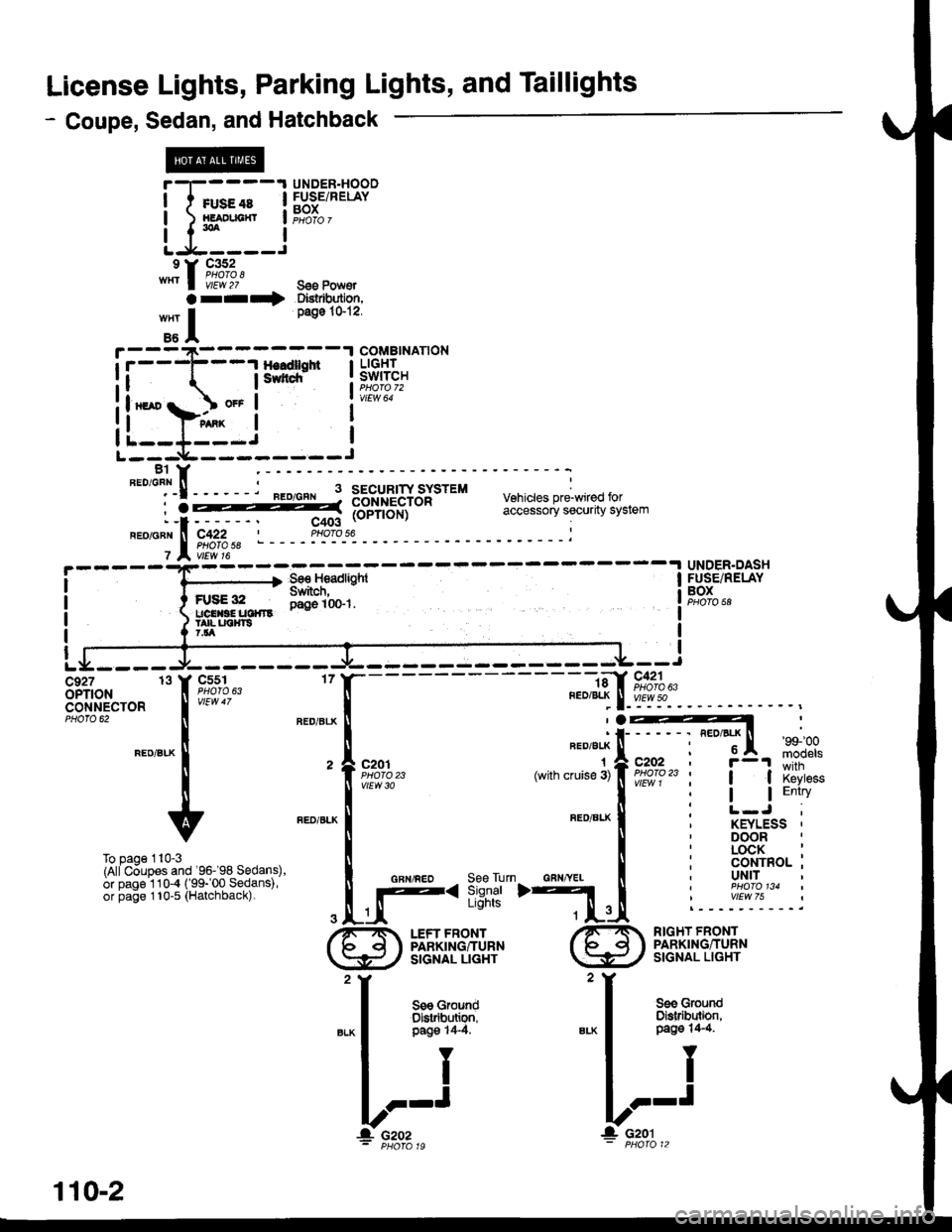
License Lights, Parking Lights, and Taillights
- Coupe, Sedan, and Hatchback
I I rusecs I
Li5:_i
"^1,1fr!;?'
arr*
HI
UNDER.DASHFUSE/RELAYBOX
UNDER.HOOOFUSE/RELAYBOX
g€o Pow€rDlstrbutiofl,page 101?.
B1 YFED/GFN ll-- -
:t! - - - '--:gsg-l 3totur['JY3;tttu vehicres pre'wired tor
: -i::-- - - -. c;A (oPrroN) ceucssu'Yir
neoionlr lf C422 | Ptloro 56I PHorc 587 A, vtEw t6
-)' 56€. Hsadlqht I
FUsEsr lYi-"'l;-. I
:]% ropnor.rt cLlEssv'v .evu"rt JtJre"'
ru9c ltz DaO€ 10$1.uclrlaEtlclllS -
ta{- uotfls7.lla
c927 13 Y CssloPTfoN I ltlglo 63
clNl.rEcroR I
-" "'
tFEoiEL( |
II
v
To Daoe 110-3(AliC6upes and '96- 98 Sedans),or page 1 10-4 ( 99- 00 Sedans),or page 110-5 (Halchback)
FED/8LK
1(with cruise 3)
RED/BLI(
GAN/YEI
AED/ELX'99100
moqelsc202r -'! wiiri| | xtYess
I I EntryI
KEYLESS '
DOORLOCK :CONTROL ;UNIT
RIGHT FRONTPARKING/TURNSIGNAL LIGHT
L.-r
/-1M LEFT FRONTfb d I PARKTNGIuRN
\Y,Z slcNAL LlcHr
'I
see Ground
"* | 3$l''Tll
II
l.?'J
! czoz- PHOfa 19
110-2
Page 2005 of 2189
- Canada\
-- f Pdoto\i3 A vttw.rsUNDER.DASHFUSE/RELAYBOX
DAYTIMERUNNINGLIGHTSCONTROLUNITvtEw 66
FUSE 2!(EUXMtIG7.5A
c420
vtEw 53
sE 20xM G Uclfr)
r'
I
I
IF
r
16
BIKWHT
See BrakeSystemIndicator Light
lcnvneo I
asl
-il*'*
IY
L_-J+: G401PHOTO 57
-
A4
B1
\BED/GRN
OAYTIMERUNNINGLIGHTSRESISTOR
S€e GroundDlstribution,page 1,1-6.PARKINGBRAKEswtTcHClosed withparking brakeapplied.H
Ughis-on Satterynpur
Hoadl8hi cornrol
lgnition
b'rak8 inputGround
Brake sysiemindicator lightcontrol
FUSE ra$r,rlxlxs ucl|l R€laY)7.ta
110-13
\
Page 2006 of 2189
Headlights (cont'd)
- How the Circuit Works
Low Beams
With the headlight switch in HEAD and the dimmer
switch in LO, current tlows through the headlight
switch. fuse 21 . fuse 22. and the low beam
tilaments to ground, and the low beams come on.
High Beams
With the headlight switch in HEAD and the dimmer
switch in Hl, current flows through the headlight
switch, dimmer switch, fuses 4, 5, and the high
beam filaments to ground, and the high beams
come on.
Current also llows through the high beam indicator
light to ground. The high beam indicator comes on
to remind the driver that the high beams are on.
Flash-to-Pass
The flash feature works with the headlight switch in
OFF, PARK, or HEAD (low beams). When you move
the flash-to-pass switch to ON, current flows
through the switch, fuses 4 and 5, and the high
beam filaments to ground, and the high beams
flash. The high beam indicator also flashes during
the flash operation. The flash function has no effect
if the high beams are already on
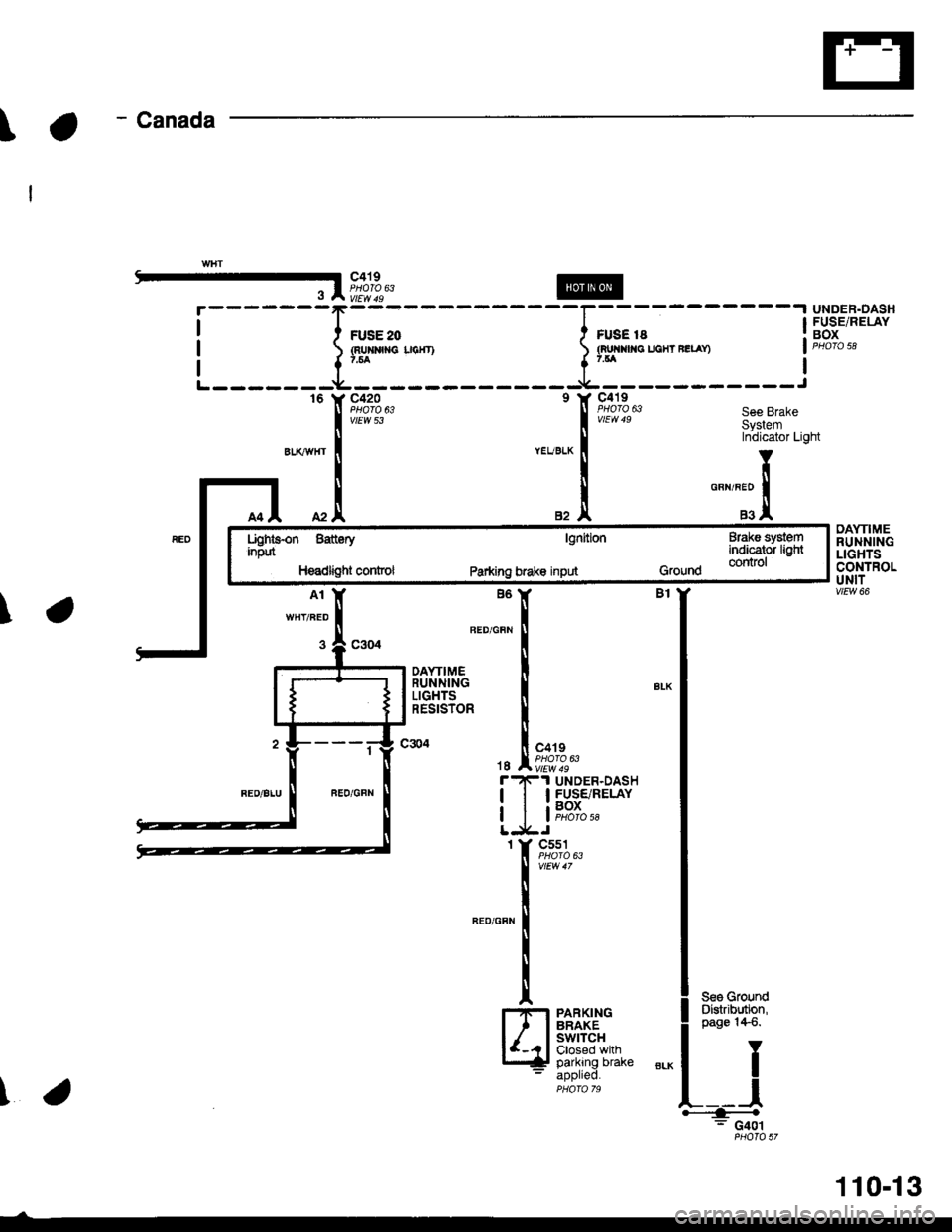
Daytime Running Lights (Canada)
When you turn the ignition to ON (ll) with the
parking brake released, the daytime running lights
control unit supplies battery voltage at the
WHT/RED wire. This voltage is applied to the high
beam headlights through the daytime running lights
resistor. Each high beam headlight receives less
than battery voltage causing them to come on at
reduced brightness.
lf the parking brake is set, a ground signal is applied
to the daytime running lights control unit at the
RED/GRN wire. lf the parking brake is set when you
first turn the ignition switch to ON (ll), the high beam
headlights will remain off until you release the
parking brake. Once the high beam headlights are
on, setting the parking brake will not turn them ofi.
When low or high beam operation is requested,
battery voltage from the headlight switch is applied
to the daytime running light control unit via the RED
wire. The daytime running lights control unit then
turns off the headlights.
Refer to the Service Manual (Section 23, Electrical)
for specific tests or lroubleshootrng procedures.
110-14